Page is loading ...

December 2014
8037A www.sencore.com | 1.605.978.4600 Revision 2.0
DMG 3200/3100/3000
Digital Media Gateway
User Manual
DMG 3200
MODULAR
HI-DENSITY
HOT-SWAP
Status
Control
SWITCH
IPIO Control
Sync In
Data A Data B
DMG 3200
DATA A
DATA BCONTROL

DMG 3200/3100/3000 – User Manual
Page 2 (306)
Copyright
© 2014 Sencore, Inc. All rights reserved.
3200 Sencore Drive, Sioux Falls, SD USA
www.sencore.com
This publication contains confidential, proprietary, and trade secret information. No part of this document
may be copied, photocopied, reproduced, translated, or reduced to any machine-readable or electronic
format without prior written permission from Sencore. Information in this document is subject to change
without notice and Sencore Inc. assumes no responsibility or liability for any errors or inaccuracies.
Sencore, Sencore Inc, and the Sencore logo are trademarks or registered trademarks in the United States
and other countries. All other products or services mentioned in this document are identified by the
trademarks, service marks, or product names as designated by the companies who market those products.
Inquiries should be made directly to those companies. This document may also have links to third-party web
pages that are beyond the control of Sencore. The presence of such links does not imply that Sencore
endorses or recommends the content on those pages. Sencore acknowledges the use of third-party open
source software and licenses in some Sencore products. This freely available source code can be obtained
by contacting Sencore Inc.
About Sencore
Sencore is an engineering leader in the development of high-quality signal transmission solutions for the
broadcast, cable, satellite, IPTV, and telecommunications markets. The company's world-class portfolio
includes video delivery products, system monitoring and analysis solutions, and test and measurement
equipment, all designed to support system interoperability and backed by best-in-class customer support.
Sencore products meet the rapidly changing needs of modern media by ensuring the efficient delivery of
high-quality video from the source to the home. More information about Sencore is available at the
company’s website, www.sencore.com
.
All trademarks and registered trademarks mentioned herein are the property of their respective owners.

DMG 3200/3100/3000 – User Manual
Page 3 (306)
Revision History
Date
Version
Description
Author
01/09/12
1.0
Initial Release
ACD
12/01/14
2.0
DMG 3200 Release
ACD

DMG 3200/3100/3000 – User Manual
Page 4 (306)
FCC Class A Information
The DMG 3200/3100/3000 has been tested and found to comply with the limits for a
Class A digital device, pursuant to Part 15 of the FCC Rules. These limits are designed
to provide reasonable protection against harmful interference when the equipment is
operated in a commercial environment. This equipment generates, uses, and can radiate
radio frequency energy and, if not installed and used in accordance with the instructions,
may cause harmful interference to radio communications. Operation of this equipment in
a residential area is likely to cause harmful interference in which case the user will be
required to correct the interference at his or her own expense.
Shielded cables must be used with this unit to ensure compliance with the Class A FCC
limits.
Warning: Changes or modifications to this unit not expressly approved by the
party responsible for compliance could void the user’s authority to operate the
equipment.

DMG 3200/3100/3000 – User Manual
Page 5 (306)
WARNING
PLEASE OBSERVE THESE SAFETY PRECAUTIONS
There is always a danger present when using electronic
equipment.
Unexpected high voltages can be present at unusual locations in defective equipment
and signal distribution systems. Become familiar with the equipment that you are
working with and observe the following safety precautions.
• Every precaution has been taken in the design of your 3200/3100/3000 to ensure
that it is as safe as possible. However, safe operation depends on you the
operator.
• Always be sure your equipment is in good working order. Ensure that all points of
connection are secure to the chassis and that protective covers are in place and
secured with fasteners.
• Never work alone when working in hazardous conditions. Always have another
person close by in case of an accident.
• Always refer to the manual for safe operation. If you have a question about the
application or operation call SENCORE for assistance.
• Never allow your equipment to be exposed to water or high moisture
environments. If exposed to a liquid, remove power safely (at the breaker) and
send your equipment to be serviced by a qualified technician.

DMG 3200/3100/3000 – User Manual
Page 6 (306)
Package Contents
The following is a list of the items that are included along with the DMG 3200/3100/3000:
1. User Manual
2. Quick Install Guide
3. AC Power Cable (2 for DMG 3200 and 3000, 1 for DMG 3100)
Note: If any option cables were ordered with the DMG 3200/3100/3000, they will be
included in the box as well.
If any of these items were omitted from the packaging of the DMG 3200/3100/3000
please call 1-800-SENCORE to obtain a replacement.
1) Documentation CD
2) Quick Install Guide
3) AC Power Cable

DMG 3200/3100/3000 – User Manual
Page 7 (306)
Table of Contents
1 Introduction ................................................................................................... 12
2 Installation and Safety .................................................................................. 13
2.1 Installation and Safety ...................................................................................................... 13
2.1.1 The 4RU Chassis ......................................................................................................... 13
2.1.2 1RU Chassis DMG 3200.............................................................................................. 15
2.1.3 Safety Considerations .................................................................................................. 16
2.1.4 Installation .................................................................................................................... 17
2.1.5 Information on Disposal ............................................................................................... 20
2.1.6 Laser Safety ................................................................................................................. 20
3 Physical Module Configuration ................................................................... 22
3.1 Connecting switch modules ............................................................................................. 22
3.1.1 Switch module with MMI .............................................................................................. 22
3.1.2 Switch module with MMI and IP IO .............................................................................. 22
3.2 MMI MicroSD Installation ................................................................................................. 23
3.3 Connecting Input Signals ................................................................................................. 23
3.3.1 IP Input ......................................................................................................................... 23
3.3.2 ASI Input ...................................................................................................................... 24
3.3.3 DVB-S/S2 Input ............................................................................................................ 24
3.3.4 COFDM Input ............................................................................................................... 24
3.3.5 DVB-T/T2 Input ............................................................................................................ 25
3.3.6 QAM A/C Input ............................................................................................................. 25
3.3.7 8VSB Input ................................................................................................................... 25
3.3.8 QAM-B Input ................................................................................................................ 25
3.3.9 SDI Encoder ................................................................................................................. 25
3.3.10 Analog Encoder ........................................................................................................... 27
3.4 Connecting Output Signals .............................................................................................. 28
3.4.1 IP Output ...................................................................................................................... 28
3.4.2 ASI Output ................................................................................................................... 28
3.4.3 QAM Output ................................................................................................................. 28
3.4.4 COFDM Cable Output.................................................................................................. 29
3.4.5 DVB-T/T2 Output ......................................................................................................... 29
3.4.6 DVB-S/S2 Output ......................................................................................................... 29
4 Administrative Settings Configuration ....................................................... 29
4.1 Accessing the Web Interface ........................................................................................... 29
4.1.1 Assigning an IP Address .............................................................................................. 33
4.1.2 IPv6 Address Support .................................................................................................. 35
4.1.3 Management over IP-Data Port and VLANs ................................................................ 37
4.1.4 Broadcast Firewall ....................................................................................................... 38
4.1.5 Internal Time Clock Setting / Network Time Protocol (NTP) Server ............................ 38
4.1.6 Automatic Daylight Saving ........................................................................................... 39
4.1.7 Password Protection in the GUI ................................................................................... 40
4.1.8 Changing the Password for the GUI ............................................................................ 40
4.1.9 Optional Languages ..................................................................................................... 41
4.2 Configuration of Clock reference module ......................................................................... 41
4.3 Licensing .......................................................................................................................... 42
4.3.1 Ordering a License File ................................................................................................ 43
4.3.2 Installing a License File................................................................................................ 43

DMG 3200/3100/3000 – User Manual
Page 8 (306)
4.3.3 Demo Licenses ............................................................................................................ 44
5 Input Configuration ...................................................................................... 44
5.1 The Inputs Node ............................................................................................................... 44
5.2 Input Analysis ................................................................................................................... 45
5.2.1 Input Port Analysis ....................................................................................................... 46
5.2.2 Input Service Filtering and Analysis ............................................................................. 47
5.2.3 Input PID Analysis ........................................................................................................ 48
5.3 Manual PSI ....................................................................................................................... 50
5.3.1 MPTS Support ............................................................................................................. 51
5.3.2 PSI Modifications of input services .............................................................................. 52
5.3.3 Defining a component type for an incoming PID. ........................................................ 52
5.3.4 Changing the language descriptor of an incoming audio ............................................ 53
5.3.5 Edit options on existing manual PSI ............................................................................ 54
5.4 Input Modules ................................................................................................................... 55
5.4.1 DVB-S/S2 Input ............................................................................................................ 55
5.4.2 ASI Input ...................................................................................................................... 60
5.4.3 QAM/DVB-C Input ........................................................................................................ 63
5.4.4 COFDM / DVB-T Input ................................................................................................. 67
5.4.5 IP Input ......................................................................................................................... 72
5.4.6 Seamless IP Input ........................................................................................................ 81
5.4.7 Dual IP Input ................................................................................................................ 84
5.4.8 8VSB Input ................................................................................................................... 85
5.4.9 QAM-B Input ................................................................................................................ 86
5.4.10 DVB-T2 Input ............................................................................................................... 88
6 Conditional Access Configuration .............................................................. 92
6.1 Descrambling – Common Interface Module ..................................................................... 94
6.1.1 Descrambling a Service ............................................................................................... 94
6.1.2 Transporting a Descrambled Service to Multiple Output Modules/Ports ..................... 94
6.1.3 CAM Configuration ....................................................................................................... 94
6.1.4 Alt CAM Mode .............................................................................................................. 96
6.1.5 CAM Interface .............................................................................................................. 97
6.1.6 Navigation .................................................................................................................... 97
6.1.6.1 Multiple Users and CAM access .................................................................................. 98
6.1.7 Error Handling .............................................................................................................. 99
6.2 Bulk Descrambling ......................................................................................................... 100
6.2.1 Verimatrix Configuration ............................................................................................ 101
6.2.2 BISS Scrambling and Descrambling .......................................................................... 103
6.2.3 SIM bulk Descrambler................................................................................................ 105
6.3 Scrambling ..................................................................................................................... 109
6.3.1 Scrambler Module Configuration ............................................................................... 110
7 Digital Output Configuration ...................................................................... 120
7.1 Input Stream Selection ................................................................................................... 121
7.2 Auto Service Modes ....................................................................................................... 123
7.2.1 Configuring an output with Auto All Services ............................................................. 123
7.3 Transport Stream Generation ........................................................................................ 125
7.3.1 Transport Settings ...................................................................................................... 129
7.3.2 Port Settings .............................................................................................................. 131
7.3.3 EMM ........................................................................................................................... 131
7.3.4 HbbTV Apps ............................................................................................................... 132
7.3.5 PSI ............................................................................................................................. 132

DMG 3200/3100/3000 – User Manual
Page 9 (306)
7.3.6 EPG............................................................................................................................ 134
7.3.7 Service ....................................................................................................................... 134
7.3.8 Components ............................................................................................................... 137
7.3.9 Scrambling ................................................................................................................. 143
7.4 Output Port Settings ....................................................................................................... 145
7.4.1 IP Output module ....................................................................................................... 145
7.4.2 Cloned IP Output Module .......................................................................................... 147
7.4.3 Dual IP Output ........................................................................................................... 150
7.4.4 ASI Output Module ..................................................................................................... 151
7.4.5 QAM Output Module .................................................................................................. 153
7.4.6 COFDM Output Module ............................................................................................. 155
7.4.7 DVB-S/S2 Output Module .......................................................................................... 157
7.4.8 DVB-T2 Output Module.............................................................................................. 160
7.5 Output Options ............................................................................................................... 161
7.5.1 Enable/Disable Services in Outgoing MPTS. ............................................................ 161
7.5.2 Virtual MPTS Output .................................................................................................. 161
7.5.3 MPTS Transparent Mode .......................................................................................... 162
7.5.4 MPTS Semi-Transparent Mode ................................................................................. 163
7.5.5 Service Filtering in Semi-Transparent Mode ............................................................. 165
7.5.6 Service Priority Selection ........................................................................................... 166
7.6 PSI/PSIP Configuration .................................................................................................. 168
7.6.1 Editing the PSI Network configuration ....................................................................... 170
7.6.2 Editing the PSI Default Values ................................................................................... 171
7.6.3 Editing the Logical Chanel Descriptor (NIT) .............................................................. 172
7.6.4 Editing the BAT table ................................................................................................. 174
7.6.5 Editing the TOT Local Time Offset Descriptor ........................................................... 174
7.6.6 PSI Synchronization ................................................................................................... 175
7.6.7 Inserting Generic Descriptors .................................................................................... 177
7.6.8 Inserting DVP STP ..................................................................................................... 179
7.6.9 PSI Generation Setup ................................................................................................ 180
7.6.10 DVB ATSC, ATSC DVB Conversion ................................................................ 181
7.6.11 SI Domain Support ..................................................................................................... 182
8 Encoder and Transcoder Configuration ................................................... 183
8.1 General information ........................................................................................................ 183
8.2 Encoder Configuration ................................................................................................... 184
8.2.1 Source Parameters .................................................................................................... 186
8.2.2 Pre Processing Parameters ....................................................................................... 187
8.2.3 Audio Parameters ...................................................................................................... 188
8.2.4 VBI/VANC Parameters............................................................................................... 190
8.2.5 Service Parameters ................................................................................................... 193
8.2.6 Analog Encoder Configuration ................................................................................... 195
8.2.7 Logo Insertion ............................................................................................................ 196
8.3 Transcoder Configuration ............................................................................................... 198
8.3.1 Source Parameters .................................................................................................... 199
8.3.2 Pre-Processing Parameters ....................................................................................... 200
8.3.3 Audio Parameters ...................................................................................................... 202
8.3.4 Configuring a service for transcoding. ....................................................................... 204
8.4 Common Encoder/Transcoder Configuration ................................................................ 206
8.4.1 Video Parameters ...................................................................................................... 206
8.4.2 Video Extended Parameters ...................................................................................... 208

DMG 3200/3100/3000 – User Manual
Page 10 (306)
8.4.3 MPEG-2 Parameters .................................................................................................. 210
8.4.4 H.264 Parameters ...................................................................................................... 210
8.5 Universal Broadcast Transcoder Configuration ............................................................. 212
8.5.1 Source Parameters .................................................................................................... 214
8.5.2 Pre-Processing Parameters ....................................................................................... 216
8.5.3 Video Parameters ...................................................................................................... 217
8.5.4 Video Extended Parameters ...................................................................................... 218
8.5.5 MPEG-2 Parameters .................................................................................................. 220
8.5.6 H.264 Parameters ...................................................................................................... 221
8.5.7 Audio Parameters ...................................................................................................... 221
8.5.8 Subtitling Parameters................................................................................................. 223
8.5.9 Logo Insertion ............................................................................................................ 224
8.6 Universal Multiscreen Transcoder Configuration ........................................................... 225
8.6.1 Video Parameters ...................................................................................................... 227
8.6.2 Audio Parameters ...................................................................................................... 228
8.6.3 Profile Parameters ..................................................................................................... 230
8.6.4 Configuration Copying ............................................................................................... 233
8.7 Statistical Multiplexing .................................................................................................... 235
8.7.1 Modules Supported .................................................................................................... 235
8.7.2 Statmux group configuration ...................................................................................... 235
8.7.3 StatMux service output configuration ......................................................................... 240
8.8 Adding Logo Images ...................................................................................................... 241
8.8.1 Uploading Logo to the MMI ........................................................................................ 241
9 Digital Processing Modules ....................................................................... 242
9.1 Audio Leveling Module ................................................................................................... 242
9.2 Electronic Program Guide (EPG) ................................................................................... 244
9.2.1 EPG Status ................................................................................................................ 244
9.2.2 Setting up EPG .......................................................................................................... 246
9.3 Adding EPG information to a Transport Stream ............................................................ 249
9.3.1 Playout Rate, Playout Limit, and Priority ................................................................... 250
9.3.2 EIT Source Setup ....................................................................................................... 252
10 Redundancy Support .............................................................................. 252
10.1 Input Redundancy .......................................................................................................... 252
10.1.1 Configuring Service-based Input Redundancy .......................................................... 254
10.1.2 Configuring Port-based Input Redundancy ............................................................... 254
10.1.3 Alarms that cause Switching ...................................................................................... 255
10.1.4 Input Redundancy and the MMI ................................................................................. 256
10.1.5 Seamless Input Redundancy ..................................................................................... 257
10.2 Internal Redundancy ...................................................................................................... 259
10.2.1 Dual backplane configuration .................................................................................... 259
10.2.2 Hardware Requirements ............................................................................................ 259
10.2.3 Configuring Modules for Internal Redundancy .......................................................... 259
10.2.4 QAM/COFDM/IP/ASI Output Internal Redundancy ................................................... 261
10.3 Output Redundancy ....................................................................................................... 262
10.3.1 Non-IP cards Output Redundancy ............................................................................. 262
10.3.2 IP Output Redundancy............................................................................................... 265
10.3.2.1 Global Settings ...................................................................................................... 266
10.3.2.2 Stream specific settings ......................................................................................... 267
10.3.2.3 Mute on Error ......................................................................................................... 269
10.4 N+m Module Redundancy.............................................................................................. 270

DMG 3200/3100/3000 – User Manual
Page 11 (306)
10.4.1 Redundancy Group Configuration ............................................................................. 272
10.4.2 Redundancy Module Configuration ........................................................................... 272
10.4.3 Manual Switching ....................................................................................................... 276
10.4.4 SDI Input switch configuration ................................................................................... 276
10.5 MMI Redundancy ........................................................................................................... 279
10.5.1 MMI Redundancy Configuration ................................................................................ 279
10.5.2 MMI Switching Criteria ............................................................................................... 283
10.5.3 Configuration Database Synchronization .................................................................. 283
10.5.4 Link between MMIs .................................................................................................... 283
10.6 Conditional Access (CA) Redundancy ........................................................................... 285
10.6.1 ECMG Redundancy ................................................................................................... 285
10.6.2 Redundancy Configuration ........................................................................................ 285
10.6.3 Manual Switching ....................................................................................................... 286
10.6.4 EMMG Redundancy ................................................................................................... 286
11 Control And Monitoring .......................................................................... 287
11.1 System Status ................................................................................................................ 287
11.1.1 Service View .............................................................................................................. 287
11.1.2 Output View ............................................................................................................... 289
11.1.3 Hardware View ........................................................................................................... 291
11.1.4 Active Alarms ............................................................................................................. 292
11.1.5 Alarm History ............................................................................................................. 293
11.1.6 Alarm Setup ............................................................................................................... 294
11.1.7 Root Cause Filter ....................................................................................................... 295
11.1.8 Monitoring Setup ........................................................................................................ 295
11.2 SNMP ............................................................................................................................. 296
11.2.1 Configuration of SNMP Alarm Filter via the GUI ....................................................... 296
11.2.2 Configuration of SNMP Trap Destination Table via the GUI ..................................... 296
11.2.3 Configuration of Trap Destination Table via SNMP ................................................... 296
11.2.4 Interpretation of Traps................................................................................................ 296
11.3 SOAP XML Interface ...................................................................................................... 297
12 Maintenance ............................................................................................ 297
12.1 Software Upgrades......................................................................................................... 297
12.2 Hot-Swapping ................................................................................................................. 297
12.2.1 Performing a Hot-Swap.............................................................................................. 297
12.2.2 Switch+MMI Module Hot-swap .................................................................................. 298
12.2.3 Other Module Hot-swap ............................................................................................. 298
12.3 Adding, Replacing, or Removing Modules ..................................................................... 298
12.4 Importing and Exporting Chassis Configuration ............................................................. 300
12.5 Restoring the Default IP Address ................................................................................... 301
12.6 Restoring the Default IP Address for 1RU (3200). ......................................................... 302
12.6.1 Resetting IP address using USB Cable ..................................................................... 302
12.6.2 Resetting IP address with DIP switch: ....................................................................... 302
Appendix A – Notices ........................................................................................ 304
Appendix B – Alarm messages......................................................................... 304
Appendix C – Warranty ..................................................................................... 304
Appendix D – Support and Contact Information ............................................. 305

DMG 3200/3100/3000 – User Manual
Page 12 (306)
1 Introduction
Thank you for purchasing the DMG 3200/3100/3000. This manual describes how to install,
configure, and operate your new equipment. It is written for professional operators of video distribution
systems and assumes a prerequisite level of technical knowledge.

DMG 3200/3100/3000 – User Manual
Page 13 (306)
2 Installation and Safety
2.1 Installation and Safety
The unit is designed to offer operators reliability and flexibility. It consists of a chassis in which a
number of modules can be installed. To cater to specific system requirements, the chassis can be
configured to host functional modules best suited for a given scenario.
Sencore products can be delivered in different chassis variations - 1RU chassis and a 4RU
chassis. The product models DMG 3000 and DMG 3200 represents the 4RU chassis, while the
product models DMG 3100 and DMG 3200 represents 1RU chassis.
2.1.1 The 4RU Chassis
The 4RU chassis consists of a total of 18 slots all of which can host functional modules. Slot
number 0 is dedicated to host the switch module and slot number 17 can only host multi-slot input
modules. Alternatively a second switch module can be placed in slot 17 for some redundancy
configurations. The remaining 16 slots are identical and can be occupied by any of the functional
modules available. A 4RU chassis including a mandatory switch module, power supply
connectors, and module slots is shown in Figure 2.1 and 2.2. Power modules and fan modules
are inserted from the back (figure 2.3 showing the DMG 3200 4RU).
Figure 2.1 – 4RU chassis (DMG 3000) with power connectors, switch module and available
slots.

DMG 3200/3100/3000 – User Manual
Page 14 (306)
DMG 3200
MODULAR
HI-DENSITY
HOT-SWAP
Status
Control
SWITCH
IPIO Control
Sync In
Data A Data B
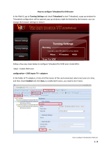
Figure 2.2 – 4RU chassis (DMG 3200) with front view
Figure 2.3 – 4RU chassis (DMG 3200) with rear view
2.1.1.1 Product models
4RU chassis models: DMG 3000 and DMG 3200
2.1.1.2 Ventilation
The 4RU chassis with Telco mounting has forced air flow from front to back in the chassis,
allowing for multiple units to be stacked above each other with no space in between. However,
adequate space must be provided in front of and behind the unit for effective ventilation. For
Broadcast mounting, air flow will be from back to front.
2.1.1.3 Replacing the power supply module
The 4RU chassis can be installed with one or two power supply modules (DMG 3200 always
comes with two power supply modules). The modules can be exchanged from the rear of the
unit. The chassis delivered with a single power module can be updated by acquiring additional
power module.
If power is lost in one of the Power supplies, the other can feed the entire chassis. It is
recommended to connect each input power at different circuits.

DMG 3200/3100/3000 – User Manual
Page 15 (306)
2.1.2 1RU Chassis DMG 3200
The 1RU chassis for the DMG 3200 holds of a total of 6 slot positions plus a slot for the
Switch/IP module. The Switch/IP module is inserted in the front of the chassis, while the
modules for the other 6 positions are inserted in the back of the chassis. All modules are hot-
swappable, including power supplies and the fan module in front.
The 1RU chassis is equipped with dual 400W AC or 500W DC power supplies
Figure 2.5 shows the front and rear view of the 1RU chassis including a mandatory switch
module, power supply connectors, and module slots.
DMG 3200
DATA A
DATA B
CONTROL
Slot #
1
Slot #
2
Slot
#3
Slot #
4
Slot
#5
Slot #
6
Figure 2.5 - 1RU chassis for DMG 3200 with dual power, switch module and available slots;
front and rear view.
This chassis can hold 2 power supply modules for redundancy purpose
2.1.2.1 Ventilation
This DMG 3200 has forced air flow from front to back allowing for multiple units to be stacked
above each other with no space in between. However, adequate space must be provided in
front of and behind the unit for effective ventilation.
The DMG 3200 has 6 fans in front. Fan speed is temperature controlled. If one fan fails,
remaining fans will increase speed to compensate. The whole Fan module, containing all 6
fans, can be hot swapped. If, during fan module replacement, the temperature on the inserted
modules exceeds a certain critical temperature, the unit will shut down, to prevent damage of
the inserted modules.
2.1.2.2 Replacing the power supply module
This 1RU chassis can be installed with one or two hot swappable power supply modules. The
modules can be exchanged from the rear of the unit. The chassis delivered with a single power
module can be updated by acquiring additional power module.
If power is lost in one of the Power supplies, the other can feed the entire chassis. It is
recommended to connect each input power at different circuits.

DMG 3200/3100/3000 – User Manual
Page 16 (306)
2.1.3 Safety Considerations
The unit must be connected to a grounded power connection. The power input connector is a
disconnect device. To remove the power from the device, the power cables needs to be
physically removed from the power input connector.
Mandatory Safety Instructions
1 The equipment must be installed by a qualified person.
2 For that equipment with grounding, connect the driver before connecting the power
cord. So opposite the power cord must be removed before removing the driver of
the ground.
3 The equipment must be installed in a restricted area where:
• Only qualified technicians have access or who know the most important
safety measures.
• Access to the area where the devices are installed will be using a tool, lock
and key, or any other safety device, and in addition the site will be
controlled by an authorized person.

DMG 3200/3100/3000 – User Manual
Page 17 (306)
2.1.4 Installation
2.1.4.1 Power supply rating
The 4RU chassis is supplied with either a 100-240V AC 50/60 Hz power or -48V DC power.
The 100-240V AC 50/60 Hz power supply is rated for maximum 300W, 400W or 800W
1
. The -
48V DC power is rated for maximum 400W. Figures 2.6. 2.7, 2.8, 2.9, 2.10, 2.11 and 2.12
below shows the power supply inlets.
The 1RU chassis is supplied with a 100-240V AC 50/60 Hz power rated for maximum 200W
for product models DMG 3100.
The 1Ru chassis, product model DMG 3200, is supplied with single or dual 100-240V AC, 47-
63Hz , 400W power, or with single or dual -48V DC, 500W power.
2.1.4.2 4RU chassis with 300 and 400W AC Power
The chassis can be hold two power supplier for redundancy and has independent power inlets
for the two supplies.
Figure 2.6 - Power Input for 4RU chassis with 300 and 400 Watt AC power
1
Contact Sencore for more information.

DMG 3200/3100/3000 – User Manual
Page 18 (306)
2.1.4.3 4RU chassis with 800W AC Power
The chassis has two power supplies for redundancy with independent power inlets. The
power supplies and power inlets are located at the back of the chassis.
Figure 2.7- Power input for 4RU chassis with 800W power supplies

DMG 3200/3100/3000 – User Manual
Page 19 (306)
2.1.4.4 4RU chassis with 400W DC (-48Volt) Power supply
The chassis can be hold two power supplier for redundancy and has independent power inlets
for the two supplies.
Figure 2.8– Front plate of dual 48V Power Supply in a DMG 3000
Figure 2.9 - Layout of 48V DC Power Supply Connector
2.1.4.5 1RU chassis Product model DMG 3200 with AC power
The power input connectors are located at the back of the unit.
Figure 2.10 Power Input Connector for 1RU Chassis, product models DMG 3200 with AC power

DMG 3200/3100/3000 – User Manual
Page 20 (306)
2.1.4.6 1RU chassis Product model DMG 3200 with DC power
The power input connectors are located at the back of the unit.
0 Volt
-48
volt
Chassis Ground
Figure 2.11 Power Input Connector for 1RU Chassis, product models DMG 3200 with DC power
2.1.5 Information on Disposal
This product must not be disposed of with other household waste. According
to the WEEE-directive, everyone that sells electrical and electronic products
shall ensure that the same products are disposed of in an environmentally
sound manner.
2.1.6 Laser Safety
The Optical SFP modules used in the DMG 3000/3100/3200 products are classified as class 1
laser products according to IEC 60825-1 and are classified as class 1 laser products per
CDRH, 21 CFR 1040 Laser Safety requirements.
Depending on the products configuration, the DMG 3000/3100/3200 products can be
equipped with multiple insertion modules containing housing for optical SFPs.
When installing SFP modules, please ensure that the module be placed in the housing present
at the front of the IP input/output module. Once inserted, the SFP module will become active.
/