Page is loading ...

C
A
U
T
I
O
N
H
O
T
MA718600i
Description
Page 5
Components
Overview
Page 6
Controls &
Indicators
Page 7
Calling For
Service
Page 10
Operation
Page 8
Specifications
Page 10
Operator
Maintenance
Page 9
Installation
Page 3
Important
Information
Page 2
Limited
Warranty
Page 11
Installation and Operation
Manual
665 Procedures Cart
Go To Table Of Contents
Style L

Owner’s Product Identification
(information that you will need to provide for servicing - key information is highlighted)
Date of Purchase
Serial Number
Name of Owner / Facility / Department Model Number
Name of Authorized Midmark Dealer Telephone # of Authorized Midmark Dealer
Address of Authorized Midmark Dealer
CA
U
T
IO
N
HO
T
MA718700i
MODEL AND SERIAL
NUMBER LOCATION
Go To Table Of Contents

CONTENTS
IMPORTANT INFORMATION .................................................................................................2
Scope and Purpose of This Manual ...............................................................................2
Intended Use of Product .................................................................................................2
Safety Instructions ..........................................................................................................2
Explanation of Safety Symbols and Notes......................................................................2
Transportation and Storage Conditions ..........................................................................3
INSTALLATION ......................................................................................................................3
Unpacking.......................................................................................................................3
Electrical Requirements..................................................................................................4
DESCRIPTION........................................................................................................................5
Introduction.....................................................................................................................5
Features..........................................................................................................................5
COMPONENTS OVERVIEW ..................................................................................................6
CONTROLS & INDICATORS .................................................................................................7
OPERATION ...........................................................................................................................8
Gas Cylinder (Model 665-003 only)................................................................................8
Drawer Heater (Model 665-002 only) .............................................................................8
OPERATOR MAINTENANCE ................................................................................................9
Preventive Maintenance .................................................................................................9
Cleaning .........................................................................................................................9
CALLING FOR SERVICE .....................................................................................................10
SPECIFICATIONS ................................................................................................................10
LIMITED WARRANTY ..........................................................................................................11

2
IMPORTANT INFORMATION
Scope and Purpose of This Manual
This manual covers complete instructions for the installation, operation, and nor-
mal care of the 665 Medical Procedures Cart. It is intended that this manual be
used by any medical personnel responsible for operating the Procedures Cart
during a medical procedure or performing operator level maintenance.
Intended Use of Product
This product is intended for use in examination / procedures environments to
accomplish general medical examinations and / or procedures.
Safety Instructions
The primary concern of Midmark is that this equipment is operated and main-
tained with the safety of the patient and staff in mind. To assure safer and more
reliable operation:
• Read and understand this manual before attempting to install or operate the
cart.
• Assure that appropriate personnel are informed on the contents of this man-
ual; this is the responsibility of the purchaser.
• Assure that this manual is located near the cart, or if possible, permanently
affixed to the cart.
Explanation of Safety Symbols and Notes
WARNING
Indicates an imminently hazardous situation which, if not
avoided, will result in death or serious injury. The DANGER
symbol is limited to the most extreme situations.
WARNING
Indicates a potentially hazardous situation which, if not avoid-
ed, could result in death or serious injury.
CAUTION
Indicates a potentially hazardous situation which, if not avoided,
may result in minor or moderate injury. It may also be used to alert
against unsafe practices.
Important
Information
Go To Table Of Contents

3
Important
Information
Transportation and Storage Conditions
• Ambient Temperature Range:..... -30°C to +60°C (-22°F to 140°F)
• Relative Humidity........................ 10% to 90% (non-condensing)
• Atmospheric Pressure ................ 500hPa to 1060 hPa (0.5 bar to 1.06 bars)
INSTALLATION
Unpacking
The Model 665 Procedures Cart is shipped in three pieces in one carton, the
cabinet, column and caster base assembly along with the mounting hardware.
EQUIPMENT ALERT
Indicates an imminently or potentially hazardous situation which, if
not avoided, will or may result in serious, moderate, or minor
equipment damage.
NOTE
Amplifies an operating procedure, practice, or condition.
EQUIPMENT ALERT
To avoid damaging the top or drawer fronts, do not use a knife or
other sharp object to open the cart’s packaging.
WARNING
The cart weighs approximately 75 lbs (34 kg). Have an
assistant help remove the cart from the packaging and as-
semble the unit. Also, use proper lifting techniques when lifting table.
Failure to do so could result in serious back injury.
Installation
Go To Table Of Contents

4
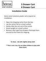
Carefully remove the cabinet,
column, caster base and hard-
ware from the packaging and
inspect for any shipping dam-
age. Report any damage to the
shipping company and fill out a
concealed damage report.
1. Position the cabinet assem-
bly (1) on its top.
2. Place the column assembly
(2) in position on the cabinet
assembly (1) aligning the
mounting holes (3).
3. Insert the four mounting
bolts (4) and tighten to a
torque of 75 to 85
inch / lbs.
4. Place the column and cabi-
net assembly in an upright
position and fully insert
(approx. 2”) the column into the caster base assembly (5)
Electrical Requirements
The electrical rating for the Model 665 Procedures Cart with an optional drawer
heater is 115 VAC, 60 Hz, 6.5 amps. The cart must be connected to a branch
circuit in accordance with local and national electric codes. To prevent possible
shock, the table’s receptacle ground continuity should be periodically tested.
CAUTION
Assure the col-
umn is fully in-
serted (approx. 2”) into the
caster base.
WARNING
All exposed metal parts of the cart are electrically grounded.
Use115 VAC, 60 HZ alternating current (AC) only. Failure to
do so could result in electrical shock to personnel and will result in
damage to table.
4
4
2
5
3
1
CA
UTION
HO
T
MA718800i
Installation
Go To Table Of Contents

5
DESCRIPTION
Introduction
The 665 Medical Procedures Cart is primarily used in examination rooms for
general examinations and minor procedures. There are two storage drawers
which accommodate supplies used during examinations.
Features
The Model 665 Procedures Cart has . . .
• an optional 50 watt heater which warms the contents of the bottom drawer.
• two storage drawers on steel ball bearing glides.
• styled drawer fronts which have molded hand pulls.
• vacuum-formed, inner drawer, divided inserts.
• an optional duplex, hospital grade, 115 VAC receptacle located on right side
of cart.
• an optional 8 ft. power cord with hospital grade grounding type plug.
• an optional gas lift assembly for raising and lowering the height of the cart.
(No electrical devices are available with the gas lift models).
Installation
Description
Go To Table Of Contents

6
COMPONENTS OVERVIEW
The illustration below shows the location of the Procedure Cart’s major compo-
nents and the chart below provides their descriptive name.
DESCRIPTION OF COMPONENTS
1. Drawer Assembly, Top 5. Column Assembly
2. Drawer Assembly, Bottom 6. Gas Lift Assembly (only on
Model 665-003)
3. Cabinet Assembly 7. Caster Base
4. Drawer Heater (only on Model
665-002)
8. Casters
8
3
6
2
1
CA
UTION
HO
T
MA718900i
4
5
7
Components
Overview
Go To Table Of Contents

7
CONTROLS & INDICATORS
The illustration below shows the location of the Procedure Cart’s controls and
indicators and the chart below describes their function.
Ref. Control Function
1 release handle
(only on Model 665-003)
used to operate the gas cylinder to raise or
lower the cabinet assembly
2 receptacle(s)
(only on Model 665-002)
provide power to accessories and / or instru-
ments used during an examination.
3 heater on / off switch
(only on Model 665-002)
turns the drawer warmer heater on or off. The
switch illuminates to indicate that the heater is
operating.
MA719000i
2
3
C
A
U
T
I
O
N
H
O
T
1
Components
Overview
Controls &
Indicators
Go To Table Of Contents

8
OPERATION
Gas Cylinder (Model 665-003 only)
The cabinet assembly table surface on the cart can be raised and lowered be-
tween 26 1/2” (67.3 cm) to 32 1/2” (82.6 cm). To raise the cabinet simply lift up-
ward on the release handle. To lower the cabinet section, while lifting the
release handle, push the cabinet section down to the desired position.
Drawer Heater (Model 665-002 only)
The drawer heater preheats
the contents of the bottom
drawer (1) to approximately
body temperature.
To operate the heater, turn the
heater on/ off switch (2) to ON
“I”. The switch will illuminate
to indicate that the heater is
operating.
To turn the heater off, turn the
heater on / off switch (2) to
OFF “O”. The switch will stop
illuminating, indicating that the
heater is no longer operating.
WARNING
Do not use the Model 665-002 Procedures Cart in an explo-
sive or oxygen-rich atmosphere. To do so could result in an
explosion or fire.
EQUIPMENT ALERT
Do not use the release handle to transport or move the cart.
Failure to comply may cause damage to the gas cylinder or lift
assembly.
CAUTION
The drawer heater may be accessed by removing the bottom
drawer; it is hot and could result in minor burns to hands. Also, the
bottom metal surface of the drawer may be hot and could result in minor
burns to your hand.
C
A
U
T
IO
N
H
O
T
1
OFF
ON
2
MA719100i
Operation
Go To Table Of Contents

9
OPERATOR MAINTENANCE
Preventive Maintenance
Little routine maintenance is required other than periodic inspection of the elec-
trical cord to ensure it is free of cuts or damage, periodic inspection of the me-
chanical functions to ensure satisfactory operation, and periodic check of
fasteners to ensure they are present and tightened securely.
Have your authorized dealer inspect your procedures cart every six months. Lu-
bricate moving parts (such as the ball bearing drawer slides) with a light ma-
chine oil or grease to assure quiet, smooth, and dependable operation.
Cleaning
Top Cabinet Surface
Regular care should be maintained by daily wiping with a damp cloth or sponge,
and periodic cleaning with a mild soap and water solution.
Painted Metal Surfaces
Wipe all painted metal surfaces with a clean cloth at least once a week. Apply
paste wax periodically to preserve the surface luster.
Drawers
To remove the drawer do the following:
1. Pull outward on the drawer until it stops.
EQUIPMENT ALERT
The material that covers the top of the cart is resistant to most me-
dicinal-types stains, but may be damaged by solvents and dyes.
Remove any fluids which are spilled on the surface immediately.
CAUTION
Turn off drawer heater and
let it cool before removing
bottom drawer for cleaning. Failure
to do so could result in minor burns.
RELEASE
MA719200i
RELEASE
1
Operation
Operator
Maintenance
Go To Table Of Contents

10
2. Depress and hold the plastic release tabs (1), that are located on the drawer
slides, up or down and continue to pull the drawer outward.
Unpainted Metal Surfaces
Wipe all unpainted metal surfaces with a clean cloth. Use petroleum jelly or oth-
er white lubricants on moving parts. Lubrication will allow free movement of
sliding parts and reduce noise.
CALLING FOR SERVICE
If you are having a problem or have a question, refer to the inside front cover of
this manual and call your dealer. Make sure that you have the information that
is highlighted on the inside front cover of this manual available. If you can’t re-
solve your question or problem with your dealer, call the following number:
1-800-Midmark (1-800-643-6275)
8:00 a.m until 5:00 p.m. (Eastern Standard Time in the U.S.)
Monday thru Friday, except for standard U.S. holidays.
SPECIFICATIONS
Weight of Cart................................ 75 lbs ( 34 kg)
Dimensions:
Cabinet Height.................................10” (25.4 cm)
Cabinet Width..................................20 3/4” (52.7 cm)
Cabinet Depth .................................18” (45.7 cm)
Cart Top Surface Height ..................30 1/4” (76.8 cm) Model 665-001 and 002
Cart Backsplash Height................... 30 7/8” (78.4 cm) Model 665-001 and 002
Cart Top Surface Height
(Fully Retracted ...............................26 1/2” (67.5 cm) Model 665-003
(Fully Extended) ..............................32 1/2” (82.6 cm) Model 665-003
Cart Backsplash Height
(Fully Retracted ...............................27 3/16” (67.5 cm) Model 665-003
(Fully Extended) ..............................33 1/16” (84.0 cm) Model 665-003
Electrical Requirements ...............115 VAC, 60 Hz, 6.5 amps
Power Cord
Length ............................................. 8 ft (243.8 cm) from bottom of cabinet.
NOTE
The drawer dividers cannot be removed but should be periodically cleaned
with a damp cloth or mild soap and water solution.
Specifications
Calling For
Service
Go To Table Of Contents

11
LIMITED WARRANTY
SCOPE OF WARRANTY
Midmark Corporation (“Midmark”) warrants to the original purchaser its new Alter-
nate Care products and components (except for components not warranted under
“Exclusions”) manufactured by Midmark to be free from defects in material and
workmanship under normal use and service. Midmark’s obligation under this war-
ranty is limited to the repair or replacement, at Midmark’s option, of the parts or the
products the defects of which are reported to Midmark within the applicable warranty
period and which, upon examination by Midmark, prove to be defective.
APPLICABLE WARRANTY PERIOD
The applicable warranty period, measured from the date of delivery to the original
user, shall be one (1) year for all warranted products and components.
EXCLUSIONS
This warranty does not cover and Midmark shall not be liable for the following: (1)
repairs and replacements because of misuse, abuse, negligence, alteration, acci-
dent, freight damage, or tampering; (2) products which are not installed, used, and
properly cleaned as required in the Midmark “Installation” and or “Installation / Oper-
ation Manual for this applicable product. (3) products considered to be of a consum-
able nature; (4) accessories or parts not manufactured by Midmark; (5) charges by
anyone for adjustments, repairs, replacement parts, installation, or other work per-
formed upon or in connection with such products which is not expressly authorized
in writing in advance by Midmark.
EXCLUSIVE REMEDY
Midmark’s only obligation under this warranty is the repair or replacement of defec-
tive parts. Midmark shall not be liable for any direct, special, indirect, incidental,
exemplary, or consequential damages or delay, including, but not limited to, dam-
ages for loss of profits or loss of use.
NO AUTHORIZATION
No person or firm is authorized to create for Midmark any other obligation or liability
in connection with the products.
THIS WARRANTY IS MIDMARK’S ONLY WARRANTY AND IS IN LIEU OF ALL
OTHER WARRANTIES, EXPRESS OR IMPLIED. MIDMARK MAKES NO
IMPLIED WARRANTIES OF ANY KIND INCLUDING ANY WARRANTIES OF
MERCHANTABILITY OR FITNESS FOR ANY PARTICULAR PURPOSE. THIS
WARRANTY IS LIMITED TO THE REPAIR OR REPLACEMENT OF DEFECTIVE
PARTS.
SF-1487 REV. A1
Limited
Warranty
Calling For
Service
Specifications
Go To Table Of Contents

12
NOTES:
Go To Table Of Contents

Go To Table Of Contents

© Midmark Corporation - 2005
003-1567-00 Rev. A (9/05)
Midmark Corporation, Versailles, Ohio 45380 U.S.A.
937-526-3662 FAX: 937-526-5542
Go To Table Of Contents
/