DMP Electronics 1100R Installation guide

Category
Security access control systems
Type
Installation guide

DMP Electronics 1100R is a wireless repeater that extends the communication range of wireless systems by forwarding messages between transmitters and receivers. It features a built-in survey capability for single-person installation, eliminating the need for an external survey kit. The 1100R provides reliable communication, indicated by a green LED, and alerts you to any issues with a red LED. It can be powered by a 12VDC power supply or an optional plug-in DC power supply and includes a rechargeable battery for up to 24 hours of backup power.

DMP Electronics 1100R is a wireless repeater that extends the communication range of wireless systems by forwarding messages between transmitters and receivers. It features a built-in survey capability for single-person installation, eliminating the need for an external survey kit. The 1100R provides reliable communication, indicated by a green LED, and alerts you to any issues with a red LED. It can be powered by a 12VDC power supply or an optional plug-in DC power supply and includes a rechargeable battery for up to 24 hours of backup power.

INSTALLATION GUIDE
1100R Wireless Repeater
Description
The 1100R Wireless Repeater provides an increased communication range by forwarding messages from the transmitter to the
wireless receiver. Up to eight repeaters can be installed on a wireless system. The repeater is powered from a 12VDC power
supply and includes a 24-hour battery backup. The 1100R Wireless Repeater provides a built-in survey capability to allow for
single-person installations, eliminating the requirement for an external survey kit.
Compatibility
All DMP 1100 Series Wireless Receivers using
Version 106 or higher software
What is Included
One Model 1100R Repeater
One Lithium Polymer Rechargeable Battery
Zone name and number label
Serial number label
Hardware pack
One (optional) Model 376L Plug-In DC
Power Supply
Program the Panel
Program the repeater in the panel as a wireless
zone. Program the wireless House Code in
System Options prior to adding DMP wireless
zones to the system. Refer to the panel
programming guide as needed.
1. In ZONE INFORMATION, enter the
wireless ZONE NO:.
2. Enter the ZONE NAME.
3. Select AUX (auxiliary) as the ZONE TYPE.
4. Program ARMED OPEN and DISARMED OPEN as TROUBLE.
5. Program ARMED SHORT and DISARMED SHORT as ALARM.
6. Select YES when WIRELESS? displays.
7. At SERIAL NO:, enter the repeater’s eight-digit serial number.
Note: If using multiple repeaters, they must be programmed as sequential zone numbers.
8. At SUPRVSN TIME, press CMD to accept the default time of 240 minutes. Press any select key to select the supervision
time required for the wireless repeater. When an 1100 series receiver is installed, powered up, or the panel is reset,
the supervision time for any repeaters and transmitters are reset.
9. Press the select key under the required number of minutes. A CHECKIN time of 60 or 240 minutes should be selected.
Note: The repeater must check in at least once during this time or a missing condition is indicated for that zone. Since
1100R repeaters automatically check in based on the supervision time selected for the wireless zone, no additional
programming is needed. Any programming prompts for contact or other information can be ignored.
J4
1
J1
1
Mounting Hole
Locations
LEDs
Tamper
Switch
Battery
Start
DC Power
2-position
Terminal
Block
Insert small
screwdriver
and lift to
remove cover
Insert small
screwdriver
and lift to
remove cover
Mounting Screw
Shoulder Washer
- +
Tamper Disable
Header
Figure 1: 1100R Repeater PCB Layout
Digital Monitoring Products 1100R Installation Guide
2
Select the Proper Location (LED Survey Operation)
The 1100R provides a survey capability to allow one person to conrm communication with the 1100 series receiver while
the cover is removed. The 1100R provides the option to power up using the Lithium battery only for survey operation.
Briey short the Battery Start pads together to power up. See Figure 1.
Survey LEDs
The 1100R automatically establishes communication with the 1100 Series receiver when powered up. The 1100R Green
Survey LED turns on steady when successful communication with the receiver is established. The 1100R Red Survey LED
turns on steady when communication cannot be established with the receiver. Relocate the repeater until the Green
LED turns on steady indicating successful communication has been established. This Green/Red survey LED operation is
different from the standard single LED ash for 1100 Series transmitters.
LED Operation
Three LEDs display repeater operation and activity. Refer to the table below as required.
Label Operation
GOOD
Green indicates reliable communication is established with the receiver. Reliable communication is dened
as the last 5 messages sent by the repeater have been acknowledged immediately by the receiver. A
message can be sent by pressing or releasing the tamper switch.
BAD
Red indicates the repeater has not established reliable communication with the receiver. Communication
is not considered reliable when the last 5 out of 15 messages sent by the repeater have not been
acknowledged immediately by the receiver. Messages may still be communicated, however the
communication link between the repeater and the receiver is not optimum. In this case the repeater
should be relocated until the Good LED returns to Green.
PWR Green indicates there is power to the repeater.
Install the Wireless Repeater
Select a Location
Mount the 1100R on a at surface. The 1100R Wireless Repeater is typically mounted between the 1100 Series Receiver
and the 1100 Series transmitter(s) that are out of range. Locate as far from the 1100 Receiver as needed to provide
the required system range. Install the repeater away from large metal objects. Mounting the repeater on or near metal
surfaces impairs performance. If the repeater is powered from an auxiliary power supply, mount the repeater away from
the metal power supply enclosure. When selecting the proper mounting location of a repeater, refer to the LED Survey
Operation section to conrm communication with the 1100 Receiver.
Enable/Disable Tampers
The 1100R is equipped with a case tamper and a wall tamper. A two position header is provided to disable the wall
tamper. To disable the wall tamper, place the jumper across the two pins of the header. If wall tamper is required,
place the jumper over just one pin for storage. When faulted, the tamper immediately sends a wireless zone short to
the panel.
Mount the Repeater
1. Insert a small screwdriver and lift to remove the cover.
2. Secure the receiver to the wall ensuring the two antennas are pointing up
and the wall tamper switch makes proper contact with the wall. Use the
supplied shoulder washers and screws in the mounting hole locations. See
Figure 1.
3. Snap the cover back on the unit after observing LED operation. Make sure
the case tamper spring is installed on the tamper switch.
Power from the External Power Supply
The 1100R can be powered from a 12VDC power supply such as a DMP Model
505-12. In addition to powering the repeater, the power supply also charges the
back-up battery of the repeater. If the DC power source is removed, the power
failure is indicated as an open condition on the repeater zone. Use the following
steps to connect the power supply:
1. Using 22 AWG wire, connect the DC Power 2-position Terminal Block to the
DC terminal on the 505-12 power supply PCB. See Figure 2.
2. Observe positive and negative polarity on all connections.
J6
+ DC -
505-12 Power
Supply
12 VDC @
2 Amps
22 AWG Wire
DC Power
2-position
Terminal Block
- +
J3
- +
Figure 2: Power Supply Connection
1100R Installation Guide Digital Monitoring Products
3
Optional External DC Plug-in Power Supply
When using the optional Model 376L plug-in DC power supply, use the
following steps to connect the power supply:
1. Connect the Black wire with White stripe to the positive terminal on
the 1100R and the Black wire to the negative terminal.
2. Mount the 1100R near a wall outlet.
In addition to powering the repeater, the DC plug-in power supply also
charges the back-up battery. The 376L plug-in DC power supply must
be located within 100 feet of the repeater using 22 AWG wire or 250
feet using 18 AWG wire.
Primary Power Loss Indication
When the 1100R is used with XT Series panels, a zone trouble indication for the repeater zone occurs within three
minutes of a loss of primary power.
When used with the XR150/XR550 Series panel, a power loss indication is displayed at the keypad as -ACPWR for the
repeater zone. This occurs within three minutes but a zone trouble report to the Central Station receiver is delayed for
one hour.
Rechargeable Battery
The 1100R rechargeable battery is used to provide up to 24 hours of backup battery power when AC power is not available.
The battery is intended for backup power only and not to operate the 1100R Repeater on a daily basis. If the battery is
low, or not plugged into the battery connector, a low battery condition is indicated for the repeater zone.
Install or Replace the Battery Assembly
Observe polarity when plugging the battery connector into the header. Use only DMP Model 1100RBAT. Replace the battery
every 3 years.
Install the Battery Assembly
Plug-in the rechargeable battery at time of installation.
1. Place the new battery and secure with the battery straps. See Figure 4.
2. Snap the battery assembly in place.
3. Observe polarity and connect the battery lead connector to the repeater battery header.
Remove the Battery Assembly
1. Remove the repeater housing cover.
2. Disconnect the battery lead connector from the repeater battery header.
3. Squeeze the battery straps to remove the battery.
J3
DC
Plug-in
Power
Supply
DC Power
2-position
Terminal Block
- +
- +
Black Wire
with White
Stripe
to Positive
Black Wire
to Negative
Figure 3: DC Plug-in Connection
J4
1
J1
1
Battery Assembly
- +
Battery Assembly
Standoff
J4
1
J1
1
- +
Figure 4: Battery Assembly
LT-0972 1.05 © 2017 Digital Monitoring Products, Inc.
800-641-4282
www.dmp.com
INTRUSION • FIRE • ACCESS • NETWORKS
2500 North Partnership Boulevard
Springfield, Missouri 65803-8877
17451
Designed, Engineered and
Manufactured in Springfield, Missouri
FCC Information
This device complies with Part 15 of the FCC Rules. Operation is subject to the following two conditions:
(1) This device may not cause harmful interference, and
(2) this device must accept any interference received, including interference that may cause undesired operation.
Changes or modications made by the user and not expressly approved by the party responsible for compliance could void the user’s authority to
operate the equipment.
Note: This equipment has been tested and found to comply with the limits for a Class B digital device, pursuant to part 15 of the FCC Rules.
These limits are designed to provide reasonable protection against harmful interference in a residential installation. This equipment generates,
uses and can radiate radio frequency energy and, if not installed and used in accordance with the instructions, may cause harmful interference to
radio communications. However, there is no guarantee that interference will not occur in a particular installation. If this equipment does cause
harmful interference to radio or television reception, which can be determined by turning the equipment off and on, the user is encouraged to
try to correct the interference by one or more of the following measures:
- Reorient or relocate the receiving antenna.
- Increase the separation between the equipment and receiver.
- Connect the equipment into an outlet on a circuit different from that to which the receiver is connected.
- Consult the dealer or an experienced radio/TV technician for help.
Listed Compliance Specications
Commercial Fire
After all transmitters are in position, the WLS option of the panel’s Walk Test must be operated and all transmitters programmed for Fire (FI) or
Supervisory (SV) must show that their checkin message was received. Refer to the panel programming guide for Trip Counter for DMP Wireless
check-in Test (WLS) which describes that both numbers of the counter must match. If not and a failed wireless zone is displayed at END, decrease
that transmitters range with the receiver and perform the WLS Walk Test again.
Powering from External 12VDC Power Supply
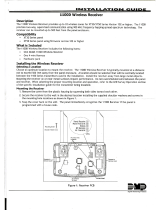
The 1100R is powered from a 12VDC power supply such as a DMP Model 505-12. In addition to powering the repeater, the power supply also
charges the back-up battery of the repeater. If the DC power source is removed, the power failure is indicated as an open condition on the
repeater zone. See page 2.
Industry Canada Information
This device complies with Industry Canada Licence-exempt RSS standard(s). Operation is subject to the following two conditions:
1. This device may not cause interference, and
2. this device must accept any interference, including interference that may cause undesired operation of the device.
Le présent appareil est conforme aux CNR d’Industrie Canada applicables aux appareils radio exempts de licence. L’exploitation est autorisée
aux deux conditions suivantes:
1. l’appareil ne doit pas produire de brouillage, et
2. l’utilisateur de l’appareil doit accepter tout brouillage radioélectrique subi, même si le brouillage est susceptible d’en compromettre le
fonctionnement.
This system has been evaluated for RF Exposure per RSS-102 and is in compliance with the limits specied by Health Canada Safety Code 6.
The system must be installed at a minimum separation distance from the antenna to a general bystander of 7.87 inches (20 cm) to maintain
compliance with the General Population limits.
L’exposition aux radiofréquences de ce système a été évaluée selon la norme RSS-102 et est jugée conforme aux limites
établies par le Code de sécurité 6 de Santé Canada. Le système doit être installé à une distance minimale de 7.87 pouces
(20 cm) séparant l’antenne d’une personne présente en conformité avec les limites permises d’exposition du grand public.
Specications
Primary Operating Voltage 8.0 to 14VDC
30mA
Standby Battery 1100RBAT
Voltage 3.7VDC
Capacity 800 mAh
Type Lithium Polymer
Rechargeable
Standby 24 hours
Frequency Range 905-924 MHz
Dimensions
Housing 4.65” L x 3.1” W x 1.4” H
Antennas 8.6” H
Color White
Housing Material Flame retardant ABS
Accessories
1100RBAT Replacement Rechargeable
Battery
505-12 12VDC Power Supply
Compatibility
All DMP 1100 Series Wireless Receivers using Version 106 or higher
software and Panels with built-in receivers
Patents
U. S. Patent No. 7,239,236
Certications
California State Fire Marshal (CSFM)
FCC Part 15 ID: CCKPC0110
Industry Canada: 5251A-PC0110
New York City (FDNY COA #6167)
Underwriters Laboratory (UL) Listed
ANSI/UL 365 Police Station Connected Burglar
ANSI/UL 609 Local Burglar Alarm Units and Systems
ANSI/UL 634 Connections and Switches for use with
Burglar Alarm Systems Accessory
ANSI/UL 639 Intrusion Detection Units Accessory
ANSI/UL 1023 Household Burglar Alarm System Units
ANSI/UL 1076 Proprietary Burglar Alarm Units
ANSI/UL 1610 Central Station Burglar Alarm Units
ANSI/UL 268 Smoke-Automatic Fire Detectors
ANSI/UL 985 Household Fire Warning System
ANSI/UL 864 Fire Protective Signaling Systems
  • Page 1 1
  • Page 2 2
  • Page 3 3
  • Page 4 4

DMP Electronics 1100R Installation guide

Category
Security access control systems
Type
Installation guide

DMP Electronics 1100R is a wireless repeater that extends the communication range of wireless systems by forwarding messages between transmitters and receivers. It features a built-in survey capability for single-person installation, eliminating the need for an external survey kit. The 1100R provides reliable communication, indicated by a green LED, and alerts you to any issues with a red LED. It can be powered by a 12VDC power supply or an optional plug-in DC power supply and includes a rechargeable battery for up to 24 hours of backup power.

Ask a question and I''ll find the answer in the document

Finding information in a document is now easier with AI