Page is loading ...

1100D Wireless Receiver
.""
,
Description
The 11000WirelessReceiver provides up to 32 wireless zones for XT30/XT50Series Version102or higher. The 11000
provides two-way,supervised communication using900 MHzfrequency hopping-spread-spectrum technology. The
receivercanbe mountedupto 500feet fromthe panelenclosure. .
Compatibility
· XT30Series panel
· XT50Series panel using firmware version 102or higher
What is Included
The11000WirelessReceiverincludesthe followingitems:
· OneModel11000WirelessReceiver
· One4-wireHarness
· Hardware pack
Installing the Wireless Receiver
Selecting a Location
Choosean optimum location to mount the receiver. The 11000Wireless Receiveris typically mounted at a distance
not to exceed 500feet away from the panel enclosure. Alocation should be selected that will be centrally located
between the 1100Series transmitters used in the installation. Install the receiver away from large metal objects.
Mountingthe receiver on or near metal surfaces impairs performance. Donot used shielded wire between the panel
and receiver. When selecting the proper mounting location and operation, refer to the LEDSurveyOperation section
of the specificinstallation guide for the transmitter being installed.
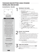
Mountingthe Receiver
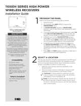
1. Removethecoverfrom the plastic housingby squeezing both sides toward each other.
2. Secure the receiver to the wall in the desired location installing the supplied shoulder washers and screws in
the mourltinghole lOGat-iorls-as~shown~iAFigUFe~.
~ - ~~ ~ =~"" =,.-,,~,- --- - - - ,------
3. Snapthe cover back on the unit. The panel immediately recognizes the 11000 Receiverif the panel is
programmed with a house code.
MountingScrew T
Shoulder Washer 'is'
Squeezeto
Remove Cover
Squeezeto _I
Remove Coler
J3Connects
ToPanel
Figure 1: Receiver PCB
Digital Monicoring Product:a
I

=iI
Zone Configuration
Referto the xnO/XT50 Series ProgrammingGuide (LT-0981)for complete wireless programming information.
Note: Whenany wireless input zone for a particular address is programmed (Ex:11-14=Addr 1), the 1100Dresponds
to the panel for this address. Other devices, such as keypads or hardwired zone expanders, cannot use this address.
Zonesconnected directly to the panel cannot be wireless.
Transmitter Survey LED Operation
DMP1100Series transmitters provide Two-way(transmit acknowledge) operation. Thisadvanced data protocol
allowseach transmitter to confirm that each of its messages (alarm, checkin, tamper, low battery) are received
and acknowledged by the 1100Series receiver. The confirmation is indicated visuallyby use of an LEDon each
transmitter. This SurveyLEDshould be used during installation to test each transmitter for proper operation. Afull
definition of the SurveyLEDfollows.
The red LEDon an 1100Series transmitter turns on when the processor wakes up to send a message. Then after a
series of communication steps are completed (successful or not), the LEDturns off when the processor goes back
to sleep. 99.9%of the time the processor is asleep in normal operation. The followinglist summarizes various
indications that can be observed on the LEDand a definition for each. Note this is for a single message. Example,
pressing and holdingthe tamper switch.
Single 1/16 second flash
·Processorwakes up
·Transmitter receives immediate synchronization from receiver
·Transmitter transmits
·Transmitter receives immediate acknowledgement from receiver
T'
Processor goes to sleep
Single Pulse greater than 1/16 second but shorter than 8 seconds
·Processor wakes up
·Transmitter receives synchronization from receiver -possiblynot immediate
·Transmitter transmits
·Transmitter receives acknowledgement from receiver -possiblynot immediate
·Processorgoes to sleep
Steady for 8 seconds
·Processorwakes up
·Transmitter never receives synchronization from receiver, or might receive synchronization
·Transmitter transmits if synchronization was received
·Transmitter never receives any further data from receiver
·Processor times out and goes to sleep
Multiple short flashes
·Processorwakes up
·Transmitter receives synchronization from receiver
·Transmitter transmits
·Transmitter receives data from receiver, but not a valid acknowledgement
·Processor brieflygoes to sleep
·Entire sequence is repeated, each short flash indicates a cycle
11000 Wireless Receiver Installation Guide
Digital Monitoring Products
3
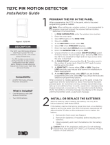
Keypad Address
Zone Numbers
XT30/XT50Series
1 11-14
2 21-24
3 31-34
4
41-44
5 51-54
6
61-64
7 71-74
8 81-84

Transmitter Supervision Time
For ULListed installations, program the transmitter supervision time in panel zone programming as listed in the
followingtable. Referto the XT30/XT50Series ProgrammingGuide (LT-0981)for complete wireless programming
information.
FCC Information
Thisdevice complies with Part 15of the FCCRules. Operation is subject to the followingtwo conditions:
(1)Thisdevice may not cause harmful interference, and
(2)this device must accept any interference received, including interference that may cause undesired operation.
Changesor modifications made by the user and not expressly approved bythe party responsiblefor compliance could void the
user's authority to operate the equipment.
Note:Thisequipment has been tested and found to complywith the limits for a ClassBdigital device, pursuant to part 15of
the FCCRules. These limits are designed to provide reasonable protection against harmful interference in a residential
installation. Thisequipment generates, uses and can radiate radio frequency energy and, if not installed and used
in accordance with the instructions, may cause harmful interference to radio communications. However,there is no
guarantee that interference will not occur in a particular installation. Ifthis equipment does cause harmful interference to
radio or television reception, which can be determined by turning the equipment off and on, the user is encouraged to try
to correct the interference byone or more of the followingmeasures:
Reorient or relocate the receiving antenna.
- Increase the separation between the equipment and receiver.
- Connect the equipment into an outlet on a circuit different from that to which the receiver is connected.
- Consult the dealer or an experienced radio/TV technician for help.
Note: The 1100 Series wireless system is a two-way supervised wireless design. It is compliant with FCCrules as they pertain to 900
MHzSpread Spectrum devices. In rare instances it has been observed that certain 900 MHzcordless telephones may occasionally
experience a clicking sound on the telephone while in use. If this occurs, it may be resolved by selecting a different channel on the
cordless telephone, or replacing the cordless phone with a different brand or model of 900 MHztelephone or other cordless telephone.
To comply with RF exposure requirements, a minimum distance of 20cm must be maintained between the antenna and all persons.
1100D Wireless Receiver Installation Guide
Digital Monitoring Products
5
I
ULListing
Listed Accessories
Supervision
Time
UL1023
Household Burglary Alarm System Units Accessory 1100R Repeater
1101/110211103/1105 Universal Transmitters
1125/ 1127W/ 1127C PIRMotion Detector
60
1135 Siren
1142 Two-Button Hold-Up Transmitter
9060/9063 Keypads
UL636
Holdup Alarm Units and Systems Accessory 1142 Two-Button Hold-Up Transmitter
60
UL634
Connections and Switches for use with Burglar Alarm 1100R Repeater
60
Systems Accessory
1101/110211103/1105 Universal Transmitters
UL639
Intrusion Detection Units Accessory
1100R Repeater
60
1125/ 1127W/ 1127C PIRMotion Detector
UL365
Police Station Connected Burglar Accessory 1100R Repeater
60
1103 Universal Transmitter
UL609
Local Burglar Alarm Units and System Accessory 1100R Repeater
60
1103 Universal Transmitter
UL1076
Proprietary Burglar Alarm Units Accessory 1100R Repeater
60
1103 Universal Transmitter
UL1610
Central Station Burglar Alarm Units Accessory 1100R Repeater
1103 Universal Transmitter
60
1135 Siren
9060/9063 Keypads
UL268 Smoke-Automatic Fire Detectors
1100R Repeater
3
1161/1162 Residential Smoke Detectors
UL985
Household Fire Warning System Accessory
1100R Repeater
1101/110211105 Universal Transmitter
240
1135 Siren
9060/9063 Keypads

Attention! Older Cordless Telephones .
Your wireless alarm system is comprised of a state-of-the-art two-way secure network created by sophisticated transmitters and
receivers. It is compliant with all FCCrules as they pertain to 900 MHzSpread Spectrum devices which require devices to share
the same frequencies. This creates a possibility of interference with other devices in your home.
It has been reported that certain older 900 MHzcordless telephones may on rare occasions experience interference (an
audible clicking sound) while in use. (This may also occur with some 2.4 GHz and 5.8 GHz telephones as many still use 900 MHz
frequencies). If this occurs on your cordless telephone, it may be resolved by selecting a different channel on your telephone.
Ifyour telephone does not have this selection, it can also be resolved by replacing your old cordless telephone with a DECT6.0
cordless telephone.
What is DECT 6.01
DECT6.0 (Digital Enhanced Cordless Telecommunications) is the current standard for cordless telephones, and it provides several
benefits over 900 MHz, 2.4 GHz and 5.8 GHz systems.
. NoMore Interference -unlike older cordless technology, DECT6.0 telephones are virtually immune to household interference,
and viceversa. Ifyou have a wirelesscomputer network in your home, DECT6.0 won't disrupt your internet use.
Encrypted Privacy -DECT6.0 has a layer of security that older cordless telephones just don't have. As information and
identity theft is on the rise, DECTencryption helps keep your pe~onal communications safe.
Call Quality - Extra security isn't just for safety; it gives you clearer calls without crossover traffic.
Battery Life - A DECT6.0 phone will last as much as 30%longer than a 5.8 GHz phone.
More information can be found on DECTtechnology at www.DECT.org.
DECT6.0 Cordless phones can be found at any major retailer including: Wal-Mart"', Target"', Best Buy"'& Radio Shack....
pecifications
OperatingVoltage
Current Draw
frequency Range
Dimensions
Receiver Housing
Antennas
Color
HousingMaterial
Patents
u.s. Patent No. 7,239,236
8.0 to 14 VDC
40mA
903-927 MHz
Listings and Approvals
California State Fire Marshal(CSFM)
FCCPart 15 Registration IDCCK1100
ICRegistration ID5251A-PC0082
Underwriters Laboratories (UL)Listed
ANSI/UL365 Police Station Connected Burglar
ANSI/UL609 LocalBurglarAlarmUnits and Systems
ANSI/UL634 Connections and Switches for use with
BurglarAlarmSystemsAccessory
HoldupAlarmUnits and System
Intrusion Detection UnitsAccessory
HouseholdBurglarAlarm System Units
Proprietary BurglarAlarm Units
Central Station BurglarAlarm Units
Smoke-AutomaticFire Detectors
Householdfire WarningSystem
4.65" Lx 3.1" Wx 1.4" H
8.6" H
White
Flame retardant ABS
ANSI/UL 636
ANSI/UL 639
ANSI/UL 1023
ANSI/UL 1076
ANSI/UL 1610
ANSI/UL 268
ANSI/UL 985
Digiaol MDnlbHing Produ.....
2500 North Partnership Boulevard
Springfield, Missouri 65803-8877
u
.=
i
u
::J
"C
e '"
......
cot!;
-§.:..
0-
...-
'c;;;;;;
~-
~=
co=
is''
o~
--
0-
N=
Q=
.".=
0-
.-
-!!!!
N~
"'-
"'~
0=
~=
/