Page is loading ...

1144 SERIES KEY FOB
TRANSMITTERS
Installation Guide
DESCRIPTION
The 1144 Series Wireless
Key Fobs include the 1144‑1
One‑Button, 1144‑2 Two‑Button,
1144‑D Dual‑Button, and 1144‑4
Four‑Button transmitters.
Each key fob features a durable
water‑resistant housing designed to
be clipped to a key ring or lanyard,
ergonomic button design, and a
status LED that indicates system
status with color‑coded responses.
Variants include models with a
1306P Prox Patch™ credential,
128‑bit AES encryption, or panic
supervision mode. For more
information, refer to “Ordering
Information”.
Compatibility
All DMP XT Series and XR Series
Panels and all 1100 Series Wireless
Receivers
To use wireless encryption, panels
must have firmware Version 183 or
higher and wireless receivers must
have firmware Version 300 or higher.
What is Included?
• One Key Fob Transmitter with
extra serial number label
• One 1306P Prox Patch credential
(1144‑1P and 1144‑2P only)
• One Sony® CR2430 3.0V Lithium
Coin Battery
• Peel‑o Button Labels (not
included with 1144‑D)
OPERATION
Each button on the 1144‑1, 1144‑2, and 1144‑4 can be individually
programmed for one of nine dierent actions. The 1144‑D provides two
buttons that, when pressed at the same time, send a panic message to the
control panel for annunciation.
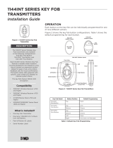
Figure 2 shows the key fob button configurations. Table 1 shows the default
programming for each button.
Figure 1: 1144-D Key Fob
Figure 2: 1100 Series Key Fob Transmitters
1144-1 and 1144E-1
1-Button Layout
1144-2 and 1144E-2
2-Button Layout
1144-D Panic
2-Button Layout
One (Top)
Button
Top
Button
Bottom
Button
Top
Button
Bottom
Button
1144-4 and 1144E-4 4-Button Layout
Top
Button
Bottom
Button
Left
Button
Right
Button
LED
Front View
Side View
Side View
with Prox Patch
Connect Key Ring or
Lanyard Here
Front
Front
Back
Back
KEY FOB MODEL BUTTON POSITION DEFAULT PROGRAMMING
1144‑1 One‑Button Top Panic
1144‑2 Two‑Button
Top Arm
Bottom Disarm
1144‑D Panic
Dual‑Button
Top and Bottom
together
Panic 2
1144‑4 Four‑Button
Top Arm
Bottom Disarm
Left Panic
Right Arm Area 1 or Perimeter
Table 1: Default Key Fob Programming

2 1144 INSTALLATION GUIDE | DIGITAL MONITORING PRODUCTS
1
PROGRAM THE PANEL
Remove the Battery Isolation Tab
To activate the battery, remove the battery isolation pull tab. When
removed, the key fob will be active and may be programmed into the
system. See Figure 3.
Program the Key Fob
After completing each of the following steps, press CMD to advance to the next option. Refer to the appropriate
panel programming guide as needed.
1. At a keypad, enter 6653 (PROG) to access the Programmer Menu.
2. (1144E Series only) Go to SYSTEM OPTIONS. At
1100ENCRYPTION, select ALL to only add encrypted wireless
devices to the system. Select BOTH to allow both encrypted
and non‑encrypted wireless devices to be programmed.
3. (1144E Series only) The default passphrase is displayed at the
ENTER PASSPHRASE prompt. Press CMD to keep the default.
Press any select key or area to change the passphrase and
enter an 8‑character hexadecimal string (0‑9, A‑F).
4. (XR Series panels only) To enable panic supervision for the
1144‑1P‑PSV, go to SYSTEM OPTIONS. At PANIC SUPERVISION,
select YES.
5. Go to ZONE INFORMATION and enter the wireless zone number. Refer to Table 2 for zone numbers.
6. (XT Series panels only) At KEYFOB select YES.
7. At KEY FOB USER NUMBER, enter an existing user number to be associated with the key fob. If the user
does not exist, the keypad displays USER X NOT IN USE. The key fob can be programmed, but the user
must be created for it to function properly.
8. At TRANSMITTER SERIAL#, enter the eight‑digit key fob serial number.
9. At TRANSMITTER SUPRVSN TIME, select a supervision time for the key fob. The default is 0 minutes. For
applications where the key fob may be taken o‑site, supervision time should be set to 0 (zero).
Program Key Fob Buttons
Refer to Table 3 when programming button actions.
1. At NO. OF KEY FOB BUTTONS,
enter the number of buttons on
the key fob (1, 2, or 4).
2. At BUTTON, select the button
that you want to program: TOP,
BTM, LFT, or RGT.
3. At BUTTON ACTION, choose an
action for the button.
4. Configure press time or output
options as needed.
5. Repeat the steps in this section
as needed for each key fob
button.
6. At the NEXT ZONE prompt,
select YES if you are finished
programming the zone. Select
NO if you would like to access
additional programming options.
7. To save panel programming, go
to STOP and press CMD.
Program the 1144-1P and 1144-2P Credential
Present the credential to a keypad or card reader to program the user credential. For information about adding
user codes, refer to the panel user guide.
PULL
Remove Battery
Isolation Tab to
Activate Battery
Figure 3: Battery Isolation Tab
PANEL MODEL ZONE NUMBERS
XR150/XR550 Series 400‑449
XT30/XT50 Series
31‑34 (slow)
41‑44 (fast)
XTLplus and XTLtouch
51‑54 (slow)
61‑64 (fast)
Table 2: Key Fob Zone Numbers
ACTION SELECT OPTIONS
Arm ARM Short/Long Press, Arm/Disarm Areas
Disarm DIS Short/Long Press, Arm/Disarm Areas
Toggle TGL Short/Long Press, Arm/Disarm Areas
Status LED STA Short/Long Press
Panic PN Output Number, Output Action
Panic (2‑button) PN2 Output Number, Output Action
Emergency EM Output Number, Output Action
Emergency (2‑button) EM2 Output Number, Output Action
Output OUT Output Number, Output Action
Sensor Reset RST Short/Long Press
Unused UN ‑
Table 3: Key Fob Button Programming Information

1144 INSTALLATION GUIDE | DIGITAL MONITORING PRODUCTS 3
ADDITIONAL INFORMATION
When a receiver is installed, powered up, or the panel is reset, the supervision time for transmitters, including key fobs, is
reset. If the receiver has been powered down for more than one hour, wireless transmitters may take up to an additional
hour to send a supervision message unless a button is pressed. This operation extends battery life. A missing message
may display on the keypad until the key fob sends a supervision message.
LED Status Operation
Depending on the programmed action of a key fob button, the Status LED turns on to acknowledge a button press or
to indicate the armed state of the system. For best results, allow the LED to turn on and then turn o before pressing
another button.
When the button is programmed for Panic, Panic 2, Emergency, Emergency 2, Output, or Sensor Reset, a 1/2second
green flash occurs to acknowledge the button press.
When the button is programmed for Arm, Disarm, Toggle Arm/Disarm, or Status, the system armed status is received
by the key fob and the LED pulses once, as shown in Table 4. The LED does not operate when a button programmed as
Unused is pressed.
LED COLOR DURATION DESCRIPTION
Red 2.0 Seconds All System On
Green 2.0 Seconds All System O
Green/Red 2.0 Seconds System On (Some Areas Armed)
Table 4: LED Operation
Replace the Battery
The 1144 Series Key Fob reports a low battery condition by automatically testing for a low battery on a daily basis. When
replacement of the key fob battery is necessary, a LOBAT message will display on the keypad. Refer to Figure 4 when
replacing the battery.
Observe polarity when installing the battery. Use only DMP ModelCR2430 3.0V coin cell batteries or equivalent Sony
CR2430 battery from a local retail outlet.
1. Insert a small flathead screwdriver into the slot at the key fob end opposite the key ring and twist to separate the
sections.
2. Push on the button area to remove
the PCB and elastomer from the hard
plastic case.
3. Gently roll the corner of the
elastomer wall down then push and
slide the old battery out of the holder
in the direction of the arrow.
4. Verify the positive side of the battery
is up and slide the new CR2430
Lithium battery into the holder and
push it into place.
5. Roll the corner of the elastomer wall
around the PCB and replace in the
front hard plastic case.
6. Snap the front and back sections
back together.
Perform a Sensor Reset to Clear LOBAT
1. Once the battery is replaced, a sensor reset is required at the keypad to clear the LOBAT message.
2. On an LCD keypad, press and hold 2for two seconds. On a graphic touchscreen keypad, press RESET. Enter your
user code, if required. The keypad displays SENSORS OFF followed by SENSORS ON.
LABEL THE KEY FOB
2
Attach the key fob to any key ring or lanyard. Select the peel‑o labels that display button programming
and place them onto the corresponding key fob buttons. For easier label installation, use a small flat head
screwdriver or hobby knife to select the label and apply it to the proper button location. Button labels can be
changed if programming is changed. Button labels are not included with the 1144‑D.
Front View
Use a small flat
head screwdriver
to separate front
and rear sections
Gently roll this corner
of the elastomer wall
down
Push battery
edge to slide
battery
Battery inside
battery
compartment
Push battery
edge to slide
battery
Insert battery
with positive
side up
Figure 4: 1100 Series Key Fob Transmitters

Designed, engineered, and
manufactured in Springfield, MO
using U.S. and global components.
LT-1449 20085
1144 SERIES KEY FOB
TRANSMITTERS
Specifications
Battery
Life Expectancy 2 years (normal operation)
Type 3V Lithium Sony CR2430
Dimensions 1.98” H x 1.53” W x 0.55” D
5.03 cm W x 3.89 cm H x 1.40 cm
Color Black
Housing Material ABS Plastic
Ordering Information
1144-D Dual-Button Key Fob
1144-1 One Button Key Fob
1144-1E One Button Key Fob with encryption
1144-1P One Button Key Fob with prox
1144-1P-PSV One Button Key Fob with prox and panic
supervision mode
1144-2 Two Button Key Fob
1144-2E Two Button Key Fob with encryption
1144-2P Two Button Key Fob with prox
1144-4 Four Button Key Fob
1144-4E Four Button Key Fob with encryption
Accessories
1144-HSG-B Key fob replacement housing, black
CR2430/10 Key fob replacement battery, 10 pack
Patents
U. S. Patent No. 7,239,236
Certifications
FCC Part 15 Registration ID CCKPC0098
INTRUSION • FIRE • ACCESS • NETWORKS
2500 North Partnership Boulevard
Springfield, Missouri 65803-8877
800.641.4282 | DMP.com
FCC INFORMATION
This device complies with Part 15 of the FCC Rules. Operation is subject to the following two conditions:
1. This device may not cause harmful interference, and
2. this device must accept any interference received, including interference that may cause undesired operation.
The antenna used for this transmitter must be installed to provide a separation distance of at least 20 cm (7.874 in.) from
all persons. It must not be located or operated in conjunction with any other antenna or transmitter.
Changes or modifications made by the user and not expressly approved by the party responsible for compliance could
void the user’s authority to operate the equipment.
Note: This equipment has been tested and found to comply with the limits for a Class B digital device, pursuant to
part 15 of the FCC Rules. These limits are designed to provide reasonable protection against harmful interference in
a residential installation. This equipment generates, uses and can radiate radio frequency energy and, if not installed
and used in accordance with the instructions, may cause harmful interference to radio communications. However,
there is no guarantee that interference will not occur in a particular installation. If this equipment does cause
harmful interference to radio or television reception, which can be determined by turning the equipment o and on,
the user is encouraged to try to correct the interference by one or more of the following measures:
1. Reorient or relocate the receiving antenna.
2. Increase the separation between the equipment and receiver.
3. Connect the equipment into an outlet on a circuit dierent from that to which the receiver is connected.
4. Consult the dealer or an experienced radio/TV technician for help.
/