Page is loading ...

Air purger
GP2
Installation, operation and maintenance manual en

Instruction for automatic air purger GP2
with RT 280 A or RT 281 A
In general
Air and other non-condensable gasses will inevitably penetrate any closed refrigeration sys-
tem. This particularly applies to refrigeration plants working at suction temperatures so low
that the suction pressure is less than the atmospheric pressure. For ammonia plants this will
conform to a suction temperature below approximately -30°C, and for R12, R22, R502, R134a
and R404a plants it corresponds to suction temperatures below -20°C, -35°C, -40°C, -25°C
and -45°C respectively.
The presence of non-condensable gasses in the condenser leads to poorer heat transmission
between refrigerant vapour and cooling water, and this reduces the condenser capacity. More-
over the total pressure, which is equal to the sum of the partial pressures, will increase in the
condenser and this means a reduction of the compressor capacity resulting in increased power
consumption and longer running time.
As the non-condensable gasses are mixed with the refrigerant vapours, there will be a consid-
erable loss of refrigerant if purging is carried out directly to the atmosphere without the use of
special cooled air purgers.
Consequently, one or several cooled air purgers should be mounted on large plants.
It is impossible to determine in advance how much air needs to be removed from a particular
plant.
Plants operating at suction pressures in the vacuum area, and which stop automatically with-
out closing of the suction stop valve, are particularly exposed. Air will then often ooze in
through the compressor shaft seal.
Instruction for automatic air purger GP2
Instruction - GP2 Air purger
010090 en 2020.12
Page 2 of 14

It applies to plants working at suction pressures in the vacuum area that flanged joints, stuff-
ing boxes on valves and similar must be tight. It is uneconomical to suck in air this way and
then remove it afterwards with an air purger.
The air purger “connection effect” on the refrigeration plant is approximately 14 kW. It is less
for plants with a lot of air and more depending of air content than of suction temperature and
condensing temperature.
For plants where the suction pressure never reaches the vacuum area, we recommend 1 air
purger per plant.
For large plants with suction pressure in the vacuum area, we recommend 1 air purger per
1,200 kW cooling capacity. These capacities apply for normal tight plants.
Mode of operation
The principle in the automatic air purger is based on the fact that refrigerant vapours can only
be cooled to the temperature corresponding to the saturation pressure of the vapours where
they condense and become liquid. Non-condensable gasses can be cooled almost unlimited. A
gas mixture of refrigerant vapours and non-condensable gasses can therefore obtain a tem-
perature considerably lower than the saturation temperature for pure refrigerant vapour at
the same pressure. On the basis of pressures and temperatures in the air purger, it can be
determined if air is present. If the temperature is lower than the saturation temperature, the
refrigerant vapour contains non-condensable gasses.
In the latter case, the temperature in the air purger will gradually fall as refrigerant vapour
mixed with air is still sucked into the vessel where the majority of the refrigerant condenses
and is removed via the AKS 38 level regulator.
This means that the quantity of air is increased and the quantity of refrigerant is reduced.
Therefore the lower the temperature, the less loss of refrigerant when purging.
Example
An ammonia plant has a condensing pressure of 13 bar, corresponding to approximately
+36°C. In this condition there is no air in the system.
However, if the condensing temperature is +32°C and the pressure is still 13 bar, there will be
1 litre of air for each 11 litres of ammonia vapour. In case of direct purging, 11 litres of am-
monia vapour will be lost for each litre of air to be purged.
If instead an air purger is installed where the gas/air mixture can be cooled to e.g. -7ºC,
there will only be approximately 0.3 litre of ammonia vapour for each litre of air. At -25ºC
there will be approx. 0.15 litre of ammonia vapour for each litre of air.
1. As shown in the piping diagram below, the air purger (10) consists of a vessel
contain-ing a cooling coil which is fed with “pump forward” liquid supply (A) via a hand
regulation valve (2). The suction connection (B) should be connected to a suction line
with the lowest possible temperature.
In the liquid supply line, a solenoid valve (3b), is controlled by the compressor switch
board in such a way that the valve closes when the compressor is out of operation.
2. The gas/air mixture is led from the condenser to the air purger via an orifice
(12), which is placed in the inlet pipe (C).
The nozzle will cause a pressure drop in such a way that a low pressure arises in the
air purger (10). The air/refrigerant mixture enters at (C) in the air purger and
through the down pipe it is led to the bottom of a distribution chamber. The nozzle
bottom, which is mounted here, ensures a regular distribution of the ascending gas
mixture. The refrigerant condenses on the cold tube coil and after the refrigerant
liquid level has risen, the refrigerant gas condenses directly in the cold refrigerant
liquid.
Instruction for automatic air purger GP2
Instruction - GP2 Air purger
010090 en 2020.12
Page 3 of 14

Instruction for automatic air purger GP2
The liquid in the bottom part of the purger will assume a temperature approximately
corresponding to the pressure above or a little lower, because the liquid is cooled by
the refrigerant, which evaporates in the coil. If the liquid level rises above the level of
the AKS 38 level controller (8) the solenoid valve (3c) opens. At the same time (3b)
closes so that the liquid in the air purger is drained.
Fig. 1: GP2 Air purger for pump circulation system.
As the air purger is filled with air, the temperature in the air filled part will fall. At the
same time, the pressure will increase because condensing has stopped.
The purging is controlled by an RT280A/RT281A (7), depending on the suction pres-
sure to which the suction side of the air purger is connected.
RT 280A is used for suction temperatures below -20°C.
RT 281A is used for suction temperatures above -20°C.
The heating element on the RT280A or 281A should not be connected.
When the difference between the liquid temperature and the pressure exceeds
approximately 1 bar, the purging starts. RT280A/RT281A (7) provides a signal to open
the solenoid valve in the purging line (3a). An orifice (12) ensures that the purging will
be done moderately without pressure chocks. A non-return valve (6) prevents
Instruction - GP2 Air purger
010090 en 2020.12
Page 4 of 14

water from the purge tank to get sucked into the air purger. Purging has stopped
again when the pressure difference has decreased approximately 0.5 bar.
4. To ensure the lowest possible temperature during purging, the air purger should be
insulated.
Mounting instruction
The air purger is delivered complete with welding branches for connection lines and fittings for
fixing irons.
If there is more than one possibility for the connection of the cooling coil inlet, select the one
with the lowest suction temperature, which is maintained during the entire operation of the
refrigeration plant. On refrigeration systems with natural circulation, the cooling coil inlet is
connected with the liquid line. On pump recirculation systems, the cooling coil inlet is connec-
ted with the liquid line from the receiver or “pump forward”. The outlet is connected to the
suction line on a system with natural circulation. On a system with pump recirculation it is
connected to the pump separator or the LP wet return. When the coil outlet is connected di-
rectly to a suction line, a thermostatic expansion valve must be applied to avoid liquid refrig-
erant in the suction line. If a thermostatic expansion valve is applied, the sensor is placed on
the suction line right after the welding point. Examples of diagrams for pump recirculation and
natural circulation can be seen in Fig. 2 and Fig. 3.
The solenoid valve in the liquid line is connected to the compressor starter relay in such a way
that the solenoid valve closes when the compressor, which sucks on the air purger cooling
coil, stops.
The purging lines (inlet for gas and non-condensable gas/air) should be connected to each
component in the relatively coldest places and in places where the vapour velocities are the
lowest. Shut-off valves are required and must be positioned in a way that allows each compo-
nent to be purged separately. Especially the condensers must be purged individually. If not,
the function of possible liquid traps, which ensure the necessary pressure drop above a con-
denser, will be damaged.
As the air purger is “self-sucking” it can be placed anywhere, for instance in the machine
room.
In case of outdoor installation, solenoid valves with waterproof coils are required. When a
thermostatic expansion valve is applied to the cooling coil and the surrounding temperature
can be lower than the evaporating temperature of the cooling coil, the sensor of the thermo-
static expansion valve must be insulated. Otherwise the low temperature will keep the valve
shut and the air purger will not be cooled by the coil. If the purger is operated without cooling
in the coil, there is a high risk that purging will take place even when non-condensable gasses
are not present. To prevent this from happening due to low surrounding temperature, an out-
door thermostat can be installed on the purging outlet pipe. This thermostat is then to be set
to cut off the purging at a surrounding temperature of more than 5°C below the temperature
of the cooling coil.
The outlet of the non-condensable gasses takes place through an orifice and a solenoid valve
controlled by the RT280A/RT281A.
On ammonia plants the outlet pipe must under no circumstances be placed in such a way that
people may unknowingly breathe in the air containing refrigerant. Further, the outlet pipe
must never be placed opposite fresh air intakes or windows which are occasionally opened.
After completed erection, the air purger should be insulated.
Instruction for automatic air purger GP2
Instruction - GP2 Air purger
010090 en 2020.12
Page 5 of 14

1) RT 280A is used for suction
temperatures below -20°C.
2) RT 281A is used for suction
temperatures above -20°C.
Instruction for automatic air purger GP2
Fig. 2: GP2 air purger for pump circulation systems – Drawing 3251-055
Item QTY PART # DESCRIPTION
1 2 1375-165 Filter FA15 3/8"
2 3 1364-514 Throttle valve REG-SA 10
3b 11372-345 Solenoid valve EVRA 3
3ac 21372-346 Solenoid valve EVRA 10
3 3 1372-330 Sol Coil
5 6 1361-187 Stop valve SVA-S 10 D
1373-298 Level Sensor Switch RT281A 1)
1996-023 Level Sensor Switch RT280A 2)
8 1 1374-034 Level Sensor Switch AKS 38
6 1 1372-245 Non return valve NRVA 15
10 14385-007 Air seperator type GP2
12 23142-034 Orifice Ø0,5
15 11361-120 Gauge valve SNV-ST CD10-W1/2 L100
16 42356-123 Gasket Ø18x1,5x10
ALP Liquid pump supply
BWet return
CGas/air from condenser/receiver
1
7
Page 6 of 14

B-B ( 1 : 7 )
E
D-D ( 1 : 7 )
E
Parts List
DESCRIPTION
PART
NUMBER
QTY
ITEM
Filter FA15 3/8" 1375-16521
Throttle valve REG-SA 101364-51432
Solenoid valve EVRA 3
1372-34513b
Solenoid valve EVRA 10 1372-34623ac
Sol Coil 1372-33033
Stop valve SVA-S 10 D
1361-18765
Level Sensor Switch RT281A 1)1373-2981
7
Level Sensor Switch RT280A 2)1996.0231
7
Level Sensor Switch AKS 38
1374-03418
Non return valve NRVA 151372-2451 6
Air seperator type GP24385-007110
Orifice 0,5
3142-034212
Gauge valve SNV-ST CD10-W1/2 L1001361-120115
Gasket 18x1,5x10
2356-123416
LP Liquid pump supplyA
Wet returnB
Gas/air from condenser/receiverC
B
B
E
DD
E
3 4 5 6 7 8 9 10
C
D
E
F
1 2 11 12
1 2 3 4 5 6 7 8 9 10 11 12
B
A
H
GG
F
E
D
C
B
A
H
Designed by
Revision No.
ECN
Title
QualityProductionEngineering
Date
Date
Date
Master drw:
Date
Sheet No.
Application
Size:
Drawing No.
Scale:
Design std.
Checked by
Modified by
Drawn by
Johnson Controls Denmark ApS
Christian X's Vej 201
DK-8270 Hjbjerg, Denmark
www.sabroe.com
Rev.
/
Revision description.
A2 Inv.
11 1
Automatics for GP2 pump circulation system
4385-007
1
Copyright - Johnson Controls Denmark ApS - All rights reserved. PROPRIETARY AND CONFIDENTIAL.
3251-055
Type of project
Order No.
ABR 15-11-2019
ABR 04-12-2019
ABR 09-01-2020
Welding
HSH 09-11-2020
5
2
55
5
5
3
3
10
8
7
LP pumplinie
From
condenser/receiver
LP wet
return/pump
separator.
LP pumplinie
From
condenser/receiver
LP wet
return/pump
separator.
Safty valve
optional
Item 15, Close
under pressure
testing
2
3b
3C
3a
1) RT280A is used for suction temperatures below -20C.
2) RT281A is used for suction temperatures above -20C.
7
The heating element
on the RT 280A or 281A
should not be connected.
15
Drain valve
optional
15
17,2
33,7
21,3
17,2
33,7
10
33,7
17,2
21 17,2
17,2
17,2
17,2
30
21,3
16
6
12
16
12 16
3
ISO7/1-Rp 1/2
16
12
13
Mouting of
orifce item 12
2
See detail E
See detail E
10
22
1
B
A
C
AC
B
C
A
B
ABR/04-12-2019
1
16 12 16
Mouting of
orifce item 12
Page 7 of 14

Instruction - GP2 Air purger
010090 en 2020.12
Liquid level
switch Danfoss
Part No
1) Suction Temp. <-20°
RT280A
3251-056
2) Suction Temp. >=-20°
RT281A
3251-057
3)Expansion valve TEA 20-1.
4) Drain Valve, optional
5) Safty Valve, optional
Gravity/natural circulation
Standard R717, rebuild for other refrigerants.
ITEM QTY PART # DESCRIPTION notat
1 2 1375-165 Fi l ter FA15 3/8"
2 2 1364-514 Throttle valve REG-SA 10
3 3 1372-330 Sol Coil
3bc 21372-346 Solenoid valve EVRA 10
3a 11372-345 Solenoid valve EVRA 3
5
4(+1)
1361-187 Stop valve SVA-S 10 D 4)
6 1 1372-245 Non return valve NRVA 15
71993-023 Level Sens or Swi tch RT 280A 1)
71373-298 Level Sens or Swi tch RT 281A 2)
8 1 1374-034 Level Sensor Switch AKS 38
9 1 1371-229 Thermostatic expansion valves 3)
10 14385-007 Ai r s epera tor type GP2
12 23142-034 Orifice Ø0,5
15 11361-120 Gauge valve SNV-ST CD10-W1/2 L100
16 42356-123 Gas ket Ø18x1,5x10
20 11364-363 Safty valve SFA 15 5)
ALiquid supply
BSuction line
CInlet for gas/air/non condensable gases
1
Instruction for automatic air purger GP2
Fig. 3: GP2 air purger for natural/gravity circulationsystems – Drawing 4350-095
Page 8 of 14

F-F
B-B
D-D
D-D ( 1 : 7 )
E
E ( 0,29 : 1 )
E ( 0,29 : 1 )
Parts List
notat
DESCRIPTIONPART NUMBERQTYITEM
Filter FA15 3/8"
1375-16521
Throttle valve REG-SA 101364-51422
Sol Coil 1372-33033
Solenoid valve EVRA 10 1372-34623bc
Solenoid valve EVRA 3
1372-34513a
4)Stop valve SVA-S 10 D 1361-1874(+1)
5
1)Level Sensor Switch RT 280A1993-02317
2)Level Sensor Switch RT 281A1373-29817
Level Sensor Switch AKS 38
1374-03418
3)Thermostatic expansion valves1371-22919
Non return valve NRVA 151372-2451 6
Air seperator type GP24385-007110
Orifice 0,5
3142-034212
Gauge valve SNV-ST CD10-W1/2 L1001361-120115
Gasket 18x1,5x102356-123416
5)Safty valve SFA 151364-363120
Liquid supplyA
Suction line B
Inlet for gas/air/non condensable gasesC
F
F
B
B
DD
D D
E
E
E
3 4 5 6 7 8 9 10
C
D
E
F
1 2 11 12
1 2 3 4 5 6 7 8 9 10 11 12
B
A
H
GG
F
E
D
C
B
A
H
Designed by
Revision No.
ECN
Title
QualityProductionEngineering
Date
Date
Date
Master drw:
Date
Sheet No.
Application
Size:
Drawing No.
Scale:
Design std.
Checked by
Modified by
Drawn by
Johnson Controls Denmark ApS
Christian X's Vej 201
DK-8270 Hjbjerg, Denmark
www.sabroe.com
Rev.
/
Revision description.
A2 Inv.
01 1
Gas purger GP2 gravity/natural circulation
4385-007
0
Copyright - Johnson Controls Denmark ApS - All rights reserved. PROPRIETARY AND CONFIDENTIAL.
4350-095
Type of project
Order No.
ABR 06-11-2019
ABR 06-11-2019
ABR 09-11-2020
Welding
ESH 09-11-2020
5
2
5
5
3
3
10
8
6
3b
20
9
9
16
12
Liquid line
Suction line
From
condenser/receiver
Ext. pressure
equalizing
Ext. pressure
equalizing
Thermostatic
expansion valves
TEA 20-1
9
16
RT 280A is used for suction temperatures below -20C. 1)
RT 281A is used for suction temperatures above -20C. 2)
The heating element
on the RT 280A or 281A
should not be connected.
16 12
16
15
Item 15, Close
under pressure
testing
12
16
16
3c
3a
2
3
5
7
4)Drain valve.
Optional
5
4)
5) Safty Valve
Optional
1
B
C
A
AC
B
1
ABR/06-11-2019
Page 9 of 14

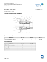
Fig. 4: Nozzles on top of air purger
Instruction for automatic air purger GP2
Approvals.
As standard CE/PED 97/23/EC, others on request e.g GGTN, DNV-GL, LRS
F-gas regulation (flourinated greenhouse gases)
Based on the Kyoto protocol regarding reduction of harmful gases in the atmosphere, the Eu-
ropean Parliament (EU) has established guidelines for the regulation of certain greenhouse
gases in a directive named “F-gas regulation”. The following is an extract from the guidelines
which is relevant for end users and operators.
Flourinated refrigerants are included in the category of greenhouse gases and therefore fall
under the F-gas regulation directive. The table below lists the relevant refrigerants and their
respective GWP (Global Warming Potential) according to the F-gas regulation.
Refrigerant
GWP (Global Warming Potential)
R134a
1300
R407C
1650
R404A
3785
R507
3850
R410A
1975
Fig4. top view
Page 10 of 14

Instruction for automatic air purger GP2
The aim of the F-gas regulation is to minimize the presence of F-gases in the atmosphere.
Purging of non-condensable gases is necessary to keep a refrigeration system running at an
acceptable efficiency. Since it is not possible to perform purging of the non-condensable gases
without a small loss of refrigerant, this emission, although not quantified, is considered inad-
vertent. A cooled non-condensable gas purger is the most efficient way to minimize the loss
of refrigerant when purging, provided the gas purger is properly refrigerated. Installing
thegas purger according to directions in this instruction will ensure that the purger is not
operat- ed without proper refrigeration.
Requirements of the F-gas regulation include:
•Labelling
•Leakage test
•Recovery of refrigerant
•Certification of personnel
• Log book.
Labelling: The unit must be fitted with a label (name plate). Refrigerant type and charge in
kg must be stated on the plate.
Leakage test: It is the operator’s responsibility to ensure that the unit is checked for leak-
ages by a certified person. For units charged with flourinated greenhouse gases, the following
conditions apply depending on type of plant and amount of charge:
•Applications containing 3 kg or more of fluorinated greenhouse gases must be
checked for leakage at least once every 12 months.
•Applications containing 30 kg or more of fluorinated greenhouse gases must be
checked for leakage at least once every 6 months.
•Applications containing 300 kg or more of fluorinated greenhouse gases must be
checked for leakage at least once every 3 months.
The applications must be checked for leakage within one month after a leak has been repaired
to ensure that the repair has been effective.
For units containing 300 kg or more of fluorinated greenhouse gases leakage detecting sys-
tems must be checked at least once every 12 months.
Recovery of refrigerant: Operators must be responsible for putting in place arrangements
for the proper recovery of fluorinated greenhouse gases by certified personnel to ensure their
recycling, reclamation or destruction.
Certification of personnel: By 4 July 2008 the member states must establish certification
and training programs for personnel involved in leakage inspections and the recovery, recy-
cling, reclamation and destruction of fluorinated gases.
Logbook: For all units containing more than 3 kg fluorinated greenhouse gases a logbook
must be kept indicating the quantity and type of product, quantities added for recharges and
the quantity recovered during servicing, maintenance and final disposal. Other relevant infor-
mation is also requested, such as identification of the servicing company or technician as well
as dates and results of the checks.
For further information please see the F-gas regulation in full.
Page 11 of 14

Te
r
m
o
s
t
a
t
i
c
E
x
p
a
n
s
i
on
Valve
with
replaceable nozzle
i
n
s
e
r
t
For other refrigerants than R717
T
h
e
r
m
o
s
t
a
t
i
c
E
x
p
a
n
s
i
on
Valve is assembled by
3
p
a
r
t
s
.
E
l
e
m
e
n
t
Danfoss no.
Valve
body
Danfoss no.
Orifice
Danfoss no.
T
h
e
r
m
o
s
t
a
t
i
c
Expans. Valve
=
E
l
e
m
e
n
t
+
Valve body
+
Orifice.
Refrigerant
Element
PartNo
Valve
Body
PartNo
Orifice
PartNo
R22/R407C
067B3250
1371.322
067B4007
1371.317
067B2789
0360003
R404A/507
067B3342
1371.140
067B4007
1371.317
067B2789
0360003
R407c
067B3278
0360034
067B4007
1371.317
067B2789
0360003
R134A
067B3297
0360035
067B4007
1371.317
067B2789
0360003
Page 12 of 14

1. Shipping
The Air purger must be blanked off and
primed on delivery. The primer is not
intended for outdoor storage. If the Air
purger is not placed in immediate service,
take precautions against corrosion or
contamination.
The Air purger must only be lifted when
empty and must not be subject to strokes or
bumps during transport. When lifting the Air
purger before it is built into the unit, always
use straps around the shell.
Please note that the weight appears from
the technical data.
A shipping description can be made when
the Air purger is built together with the unit.
2. Installation
The site and personal protection must be in
accordance with EN 378-3 or national
requirements.
Immediately upon receipt, the Air purger must be
checked for any damage occurred during
transport. If the Air purger is damaged, the unit
must not be installed and started.
When placing the Air purger, make sure to
leave enough room for inspection,
maintenance, escape and emergency.
Foundations must be sufficiently robust, as
their purpose is to provide permanent
support without settling and to absorb any
normal vibrations from outside causes.
The Air purger is equipped with support for
horizontal installation.
Blanked off branches must be cut off at the
cutting groove depending on metal
thickness on adjoining tubes. Make sure
that no impurities get into the Air purger
during installation.
Do not remove protective plugs and covers
until immediately before installation.
The entire system must be clean before
starting operation. Under certain conditions,
the use of strainers in the piping may be
required.
When fitting the tube connections, make
sure that tensions in the Air purger during
test, start up, operation and stand still do
not exceed the allowable values. Vibrations
must be minimised possibly by means of a
vibration damper.
Apart from branch connections, saddle
plates and supports, welding must not be
carried out on the Air purger.
The Air purger must be secured against
exceeding the allowable pressures and
temperatures.
All outer surfaces must have a surface
coating, which allows the Air purger to be
installed in an environment without it
causing corrosion.
Hot surfaces must be marked ”Hot”.
3. Safety equipment
Before the Air purger is put into service, it
must be provided with safety equipment.
The manufacturer of the refrigerating plant
carries the responsibility for the safety
equipment, as it is not included in the Air
purger supply.
4. Start up and operation:
Before start up, make sure that connections
are tight.
To avoid any accidents or personal injury,
the person responsible for the plant must
make sure that the operating staff is duly
trained and instructed before the
refrigeration plant is started.
The instruction should be based on the Unit
Instruction Manuals and should include
instruction in construction, supervision,
operation and maintenance of the system
as well as the handling of used refrigerant.
Evacuation and filling with refrigerant must
be carried out according to the description
in the Unit Instruction Manual.
Before use the refrigeration plant must be
leak tested and inspected by an expert.
Local safety and health regulations must be
observed.
The expert makes a certificate to be kept by
the user.
Under no circumstances must the Air purger
operate at temperatures or pressures higher
than the ones indicated in the design
specification. Excessive operation can
cause stress and severely damage the Air
purger tube bundle.
Temperature shocks
The Air purger should not be subjected to
abrupt temperature fluctuations. Hot fluids
must not suddenly be introduced when the
unit is cold, nor must cold fluids suddenly be
introduced when the unit is hot.
Page 13 of 14

5. Maintenance:
Only qualified personnel must carry out
inspection.
Operating experience will determine how
often the Air purger needs to be inspected /
checked. It depends on the operating
conditions. SABROE recommends
inspection of the Air purger to be carried out
at monthly intervals during the running-in
period. After a running-in period of six
months, a maintenance plan must be made.
SABROE recommends inspection to be
carried out every third month as a minimum.
Do not dismount or tighten connections
when the equipment is under pressure.
Periodic inspection during the life of the Air
purger must meet the requirements in
national legislation or EN 378-2.
Correspondingly, a visual inspection of
connections, outer surfaces, bases, the
vibration damper and safety equipment
must be carried out.
If corrosion, erosion or other weaknesses in
the Air purger are found, the Air purger must
be inspected by a qualified authorised third
party, who will give the necessary
permission to continue use of the Air purger.
If repair is requested, approved personnel
together with a qualified third party and
SABROE will carry this out. If a permission
to continue use of the Air purger is not
granted the Air purger must be scrapped.
Internal cleaning during normal operation is
not needed. The Air purger can be cleaned
by chemical methods. The operator of the
plant decides which method to be used. The
appropriate method depends on the type of
deposit and the facilities available in the
plant. If possible, contact a qualified
cleaning organisation, which provides the
appropriate method.
6. Spare Parts and Replacement Parts:
Spare parts and replacement parts can be
ordered directly from SABROE. When
ordering parts, please provide the name of
the part needed, as well as the Air purger
serial number, type, size, and other
information from the nameplate.
7. Environmentally Correct Removal:
The Air purger does not contain
environmentally damaging material, such as
asbestos, mercury or heavy metals.
All parts of the Air purger can be re-used
after being scrapped.
-The refrigerant must be drained off
before destruction
-All steel materials can be used again
after re-melting.
-During the re-melting process coating
will disappear without damaging the
environment.
Page 14 of 14
/