Page is loading ...

579-1102 Rev H
*05791102H*
4007ES and 4007ES Hybrid Fire Alarm Systems
Installation Manual

This page is intentionally blank

Contents
CONTENTS
1 Cautions, Warnings, and Regulatory Information.......................................................................................................3
2 Overview...........................................................................................................................................................................4
2.1 4007ES product list.............................................................................................................................................................................................. 4
2.2 Glossary.................................................................................................................................................................................................................5
3 Installation........................................................................................................................................................................6
3.1 Mounting the 4007ES panels..............................................................................................................................................................................6
3.2 Trim Kit.................................................................................................................................................................................................................. 7
3.2.1 Trim kit application................................................................................................................................................................................................................7
3.3 Wiring.....................................................................................................................................................................................................................8
3.3.1 Safety ground/ ferrite bead.................................................................................................................................................................................................9
3.3.2 AC supply wiring.....................................................................................................................................................................................................................9
3.3.3 Battery guidelines............................................................................................................................................................................................................... 10
3.4 Power...................................................................................................................................................................................................................10
4 NAC power supply.........................................................................................................................................................11
4.1 NAC power supply specifications.....................................................................................................................................................................12
4.2 NAC section overview........................................................................................................................................................................................12
4.3 Specifications......................................................................................................................................................................................................13
4.3.1 Wiring parameters.............................................................................................................................................................................................................. 13
4.3.2 Wiring distances.................................................................................................................................................................................................................. 14
4.3.3 Class A wiring....................................................................................................................................................................................................................... 14
4.3.4 Class B wiring....................................................................................................................................................................................................................... 15
4.4 Troubleshooting................................................................................................................................................................................................. 16
5 IDNAC power supply.....................................................................................................................................................17
5.1 Power supply specifications............................................................................................................................................................................. 18
5.2 IDNAC section overview.................................................................................................................................................................................... 18
5.3 Specifications......................................................................................................................................................................................................19
5.4 Wiring parameters............................................................................................................................................................................................. 19
5.5 IDNAC Class B wiring tables............................................................................................................................................................................. 20
5.6 IDNAC Class B wiring......................................................................................................................................................................................... 21
5.7 Compatible devices and appliances................................................................................................................................................................ 22
5.8 Auxiliary relays section overview..................................................................................................................................................................... 25
5.9 Troubleshooting................................................................................................................................................................................................. 26
5.9.1 SLC channel trouble LED codes...................................................................................................................................................................................... 27
5.9.2 System trouble LED codes................................................................................................................................................................................................28
6 4007ES power supplies.................................................................................................................................................29
6.1 Power supplies specifications.......................................................................................................................................................................... 29
6.2 Wiring guidelines................................................................................................................................................................................................29
6.3 IDNet Section overview..................................................................................................................................................................................... 30
6.4 Device addressing, Class A and Class B.......................................................................................................................................................... 30
6.5 Wiring parameters............................................................................................................................................................................................. 31
6.6 Class A Wiring.....................................................................................................................................................................................................32
6.7 Class B Wiring.....................................................................................................................................................................................................32
6.8 Auxiliary power selection.................................................................................................................................................................................. 33
6.9 RUI section.......................................................................................................................................................................................................... 34
6.10 Troubleshooting................................................................................................................................................................................................. 36
7 Optional modules and cards....................................................................................................................................... 37
7.1 Example of combinations................................................................................................................................................................................. 38
8 Appendix A ULC programming requirements........................................................................................................... 39
8.1 Common earth fault ground and common trouble indicator......................................................................................................................39

This page is intentionally blank

4007ES and 4007ES Hybrid Fire Alarm Systems Installation Manual
Page 3 579-1102 Rev H
1 Cautions, Warnings, and Regulatory Information
READ AND SAVE THESE INSTRUCTIONS Follow the instructions in this installation manual. These instructions must be followed to avoid damage to
this product and associated equipment. Product operation and reliability depend upon proper installation.
DO NOT INSTALL ANY SIMPLEX™ PRODUCT THAT APPEARS DAMAGED Upon unpacking your Simplex product, inspect the
contents of the carton for shipping damage. If damage is apparent, immediately file a claim with the carrier and notify an authorized
Simplex product supplier.
ELECTRICAL HAZARD Disconnect electrical field power when making any internal adjustments or repairs. All repairs should be
performed by a representative or an authorized agent of your local Simplex product supplier.
STATIC HAZARD Static electricity can damage components. Handle as follows:
• Ground yourself before opening or installing components.
• Prior to installation, keep components wrapped in anti-static material at all times.
EYE SAFETY HAZARD Under certain fiber optic application conditions, the optical output of this device may exceed eye safety limits. Do
not use magnification (such as a microscope or other focusing equipment) when viewing the output of this device.
SULFURIC ACID WARNING Battery contains sulfuric acid, which can cause severe burns to the skin and eyes and can destroy
fabric. Replace any leaking or damaged battery while wearing appropriate protective gear. If you come in contact with sulfuric acid,
immediately flush skin or eyes with water for 15 minutes and seek immediate medical attention.
FCC RULES AND REGULATIONS – PART 15 This equipment has been tested and found to comply with the limits for a Class A digital device, pursuant
to Part 15 of the FCC Rules. These limits are designed to provide reasonable protection against harmful interference when the equipment is operated
in a commercial environment. This equipment generates, uses, and can radiate radio frequency energy and, if not installed and used in accordance
with the instruction manual, may cause harmful interference to radio communications. Operation of this equipment in a residential area is likely to
cause harmful interference in which case the user will be required to correct the interference at his own expense.
SYSTEM REACCPTANCE TEST AFTER SOFTWARE CHANGES To ensure proper system operation, this product must be tested in accordance with
NFPA-72, after any programming operation or change in site-specific software. Reacceptance testing is required after any change, addition or deletion
of system components, or after any modification, repair or adjustment to system hardware or wiring. All components, circuits, system operations,
or software functions known to be affected by a change must be 100% tested. In addition, to ensure that other operations are not inadvertently
affected, at least 10% of initiating devices that are not directly affected by the change, up to a maximum of 50 devices, must also be tested and proper
system operation verified.

Page 4 579-1102 Rev H
4007ES and 4007ES Hybrid Fire Alarm Systems Installation Manual
2 Overview
The 4007ES fire alarm control panel provides audible and visible indication of alarms, troubles, and supervisory conditions. The 4007ES panels
supports addressable notification and initiating devices and the 4007ES Hybrid panels supports non-addressable notification devices and addressable
initiating devices*. The panel can be configured by using a panel programmer.
*From this point on, the 4007ES and the 4007ES hybrid is referred to as 4007ES, unless stated otherwise.
4007ES operator instructions are described in the 4007ES Operator’s Manual 579-1165.
4007ES programming instructions are described in the 4007ES Programmer’s manual 579-1167.
2.1 4007ES product list
Table 1: Product list
Part number Base panels
4007-9101 4007ES Hybrid, red
4007-9201 4007ES, red
4007-9102 4007ES Hybrid, platinum
4007-9202 4007ES, platinum
Table 2: Product List and manual
Part number Optional modules: field installed Manual
4007-9801 Zone/Relay Module 579-1103
4007-9802 25V Regulator Module 579-812
4007-9803 IDNet+ Loop Expansion Module 579-1106
4007-9804 Dual Class A Module 579-1029
4007-9805 LED Module 579-1105
4007-9806 DACT Module 579-954
4007-9807 City Circuit with Disconnect Module 579-955
4007-9808 City Circuit without Disconnect Module 579-955
4007-9809 Relay Module 579-955
4007-9810 4120 NIC 579-956
4007-9812 Dual RS-232 Module 579-910
4007-9813 Wired Media Card 579-956
4007-9814 Fiber-Optic Media Card 579-956
4190-6106 TrueInsight Remote Service Gateway and Programming 579-953

Page 5 579-1102 Rev H
4007ES and 4007ES Hybrid Fire Alarm Systems Installation Manual
2.2 Glossary
Table 3: Glossary
Term Definition
Aux Abbreviation for Auxiliary; typically used to describe Auxiliary Power.
EOL
End-of-Line, typically in reference to and end-of-line resistor or EOL
resistor.
FACP Fire Alarm Control Panel.
Hybrid
In this document, “Hybrid” the 4007ES Hybrid models that provide both
addressable and conventional initiation with conventional non addressable Notification Appliance Circuits.
IDC Initiating Device Circuit.
IDNet Addressable SLC for up to 250 addressable devices.
IDNet+ IDNet which is electrically isolated from internal panel electronics.
IDNAC Individual Device Notification Appliance Circuit (Addressable).
NAC Notification Appliance Circuit, formerly called signal circuit.
NIC Network Interface Card for the 4120 network.
Regulated 24 DC
Notification appliance operation that meets the minimum listing
requirements; inrush currents typically require power supply and NAC rating.
RS-232 module
The Dual RS-232 interface module provides a serial communication
interface to an AC or DC printer, a PC Annunciator, or a third party computer.
RUI
Remote Unit Interface; SLC for communications with remote
annunciators.
Simple NAC
A Reverse Polarity Supervised Notification Appliance Circuit that is
capable of on steady or coded operation. Sync or SmartSync operation is not supported.
SLC Signaling Line Circuit
SmartSync
A reverse polarity monitored NAC capable of synchronizing and
controlling both horns and strobes on the same circuit using a proprietary signaling protocol. Used as the
protocol for TrueAlert Non-Addressable Devices.
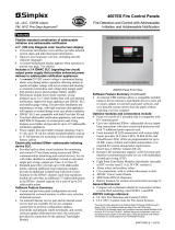
User interface The user interface is a 4.3 in. (109mm) diagonal color LCD with a built-in resistive touch panel and 12 indicating LEDs. The color LCD
provides system status and access to perform system functions and to change the system configuration.
Figure 1: 4007ES panel inside view on page 5 shows an inside view of the 4007ES panel with the optional LED module (4007-9805) installed.
Fig 1: 4007ES panel inside view

Page 6 579-1102 Rev H
4007ES and 4007ES Hybrid Fire Alarm Systems Installation Manual
3 Installation
Introduction
This chapter describes how to install the 4007ES panel. It can be semi-flush or surface mount.
3.1 Mounting the 4007ES panels
• Due to the danger of metal fragments falling into electronics when drilling the holes for the conduits, remove the electronics in the system:
- To remove the electronics, unscrew the ten screws. Remove the power supply and store it in a safe, clean, and dry location until the panel
installation is completed, see Figure 2: Screws location on page 6.
- If installing a 4007ES hybrid panel, also remove the Zone/Relay card (three screws).
• Use a suitable punch where a conduit entrance is required. The knockouts are not provided. Locate and create on-site as required during installation.
Fig 2: Screws location
• For surface or semi-flush mounting to a wooden wall structure, the panel must be attached with four 1 1/2 in. (38 mm) long lag bolts and four 1/2 in.
(13 mm) diameter washers, supplied by others.
• For surface mounting, secure the box to the wall using the tear-drop mounting holes on the back surface. For semi-flush mounting, secure the box
along the sides to the wall studs. Note that the front surface of the back box must protrude at least 1-1/2 in. (38mm) from the wall surface for semi-
flush installation. A trim kit is supplied for semi-flush mounting, see the Trim kit application on page 7 section for more information.
• To install the panel, see Figure 3: Back Box Installation dimensions and Semi-Flush Mounting (Right) on page 7 for the dimensions and use the
holes in the back box to secure it to the wall.

Page 7 579-1102 Rev H
4007ES and 4007ES Hybrid Fire Alarm Systems Installation Manual
Fig 3: Back Box Installation dimensions and Semi-Flush
Mounting (Right)
3.2 Trim Kit
3.2.1 Trim kit application
Trim kits are used to cosmetically cover wall openings when boxes are mounted semi-flush into the wall. The kit includes:
• Two top trim bands (shorter).
• Two side trim bands (longer).
• Four corner pieces.
Fig 4: Semi-flush trim kit
After mounting the box semi-flush to the wall, attach the trim per the following procedure:
1. The strips need to be cut before being attached. Carefully cut them to length using a hacksaw or sharp utility knife. Cut the strips approximately
1in. (25 mm) shorter than the box dimension. The box is 20-7/8 in. (530 mm) wide and 20-3/16 in. (512 mm) high.
2. Attach the strips one at the time. Peel off the adhesive tape release and center the strip on the box placing the edge of the strip against the box
surface, then press solidly to assure adhesion.
3. Each corner piece overlaps the trim strip slightly less than 3/4 in. (19 mm). Align the corner pieces tight to the box corner and attach with a drywall
or similar screw, suitable for the wall material. The screws are not supplied.
Fig 5: Applying the trim

Page 8 579-1102 Rev H
4007ES and 4007ES Hybrid Fire Alarm Systems Installation Manual
3.3 Wiring
Wiring guidelines
Follow these guidelines when connecting power-limited (PL) systems. For more information about these guidelines, contact your authorized Simplex
product supplier.
• Non-power limited (NPL) field wiring (AC power, batteries, City connection, DACT) must be installed and routed in the shaded areas shown in Figure 6:
Field wiring guidelines (NAC power supply shown as reference) on page 8
• You must maintain a minimum of 0.25 in. (6.35 mm) space between NPL and PL field wiring.
• The AC harness is pre-wired and tied to back of the box.
Fig 6: Field wiring guidelines (NAC power supply shown as reference)
• The conductors must test free of all grounds.
• A system ground must be provided for earth detection and lightning protection devices. This connection must comply with approved earth detection
per NFPA780.
• Splicing is permitted. All spliced connections must either be soldered (resin-core solder), crimped in metal sleeves, or encapsulated with an epoxy
resin. When soldering or crimped metal sleeves are used, the junction must be insulated with a high-grade electrical tape that is as sound as the
original insulating jacket. Shield continuity must be maintained throughout.
• Excess slack should be kept to a minimum inside the back box enclosure. The wiring should be neatly dressed and bundled together using wire ties.
• All wiring must use copper conductors only, unless noted otherwise.
• For IDNet, shielded wire is not recommended. If shielded wires are present, cut and tape off the shield at each end in the panel to prevent it coming
into contact with other components. The metallic continuity of the shield must be maintained and insulated throughout the entire length of the
cable.
• If shielded wire is used, the metallic continuity of the shield must be maintained throughout the entire cable length, and the entire length of the cable
must have a resistance greater than 1 megohm to earth ground. Underground wiring must be free of all water.

Page 9 579-1102 Rev H
4007ES and 4007ES Hybrid Fire Alarm Systems Installation Manual
Fig 7: EOL relay diagram
• In areas of high lightning activity, or in areas that have large power surges, use the 2081- 9027 or the 2081-9044 Transient Suppressor on monitor
points.
• Wires must not be run through elevator shafts.
• Only system wiring can be run together in the same conduit. When powering remote units using relay contacts, power for these circuits must be
provided by a PL power supply listed for fire-protective signaling use. An end-of-line (EOL) relay must be used to supervise the auxiliary power circuit.
• Connect the output of the EOL relay to cause a trouble. Wire in series with the EOL resistor on an available initiating device circuit (IDC) or individual
addressable module (IAM).
3.3.1 Safety ground/ ferrite bead
Correct operation and protection against transient energy in accordance with UL 864 and ULC-S527 require the connection of safety ground wire to
cabinet chassis. Connect the safety ground before wiring any other circuits to the panel. Ferrite beads must be attached to the incoming AC power line
as shown in Figure 8: Safety ground and ferrite bead on page 9. Wrap the line leg twice through a ferrite bead, and the neutral leg of the power
line twice through the other ferrite bead.
Fig 8: Safety ground and
ferrite bead
NOTE: The ferrite bead should be installed as close as possible to where power enters the panel.
3.3.2 AC supply wiring
Adhere to the following guidelines when wiring AC Power. See Safety ground/ ferrite bead on page 9 for information about attaching the ferrite
bead to the AC power wires.
• The AC power must be wired from a dedicated circuit breaker or fuse, rated no more than 20 A, in accordance with NFPA-72, NEC, and local codes.
• Before handling the AC feed, verify that it is not live using a voltmeter. Make sure the circuit is de-energized and tagged to prevent injury.
• The AC supply wiring must be 14 AWG minimum to 12 AWG maximum.
• Connect a 12 AWG copper ground wire from safety ground in the electrical distribution panel to the panel safety ground stud.
• Input voltage:
- 120 VAC, 50/60 Hz.
- 240 VAC, 50/60 Hz.
No configuration settings required to select.

Page 10 579-1102 Rev H
4007ES and 4007ES Hybrid Fire Alarm Systems Installation Manual
3.3.3 Battery guidelines
A fused harness is required to connect the backup batteries. Use harness 734-304 for a NAC power supply, and harness 734-303 for an IDNAC power
supply. The harness is shipped with the panel. The mating spade lug on the battery should be 0.250 in. X 0.032 in. (6.35 mm X 0.81 mm). If another size
is needed, you need to replace the battery terminal connectors on the supplied battery harness.
• The 4007ES battery charger supports up to 33 Ah batteries (maximum) within UL864 and ULCS527 guidelines.
- 18 Ah batteries can fit inside the box.
- 25 Ah and 33 Ah batteries use 2081-9282(red 25 Ah or 33 Ah) or 4009-9801 (beige 25 Ah).
• To minimize the power losses due to wiring from the external battery box to the 4007ES, use at least a 12 AWG wire. Mount the battery box within 20
feet (609.6 cm) of the panel in accordance with the mounting instruction label in the box. All interconnecting wiring must be enclosed in conduit.
• Seismic battery brackets can be used internally in the 4007ES box (the 2081-9401: 12.7 Ah bracket, and the 2081-9402: 18 Ah bracket). For more
information on how to install the seismic brackets, see the Battery Bracket installation instructions (579-944).
3.4 Power
Final installation To finalize the installation:
1. Reinstall the power supply and the electronics.
2. To install the batteries:
a. Place the first battery on the left side of the panel to avoid interference with the DACT, if installed.
NOTE: The battery terminals should face the front of the box.
b. Insert the second battery and make sure it is snugly positioned beside the first battery.
c. Wire the batteries in series such that you have 24 V. Use the white wire provided to bridge the batteries together, see Figure 9: Power supply on
page 10.
IMPORTANT: Verify all field wiring before applying any power to the panel.
Power up the system:
1. Connect the negative lead to the battery.
2. Apply AC.
3. Connect the positive to the battery.
Fig 9: Power supply

Page 11 579-1102 Rev H
4007ES and 4007ES Hybrid Fire Alarm Systems Installation Manual
4 NAC power supply
A conventional reverse polarity NAC power supply is used in a 4007ES hybrid panel. It provides 6A and can support the following:
• Non-addressable notification devices.
• Addressable initiating devices.
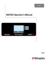
See Figure 10: NAC power supply on page 11 and Table on page 11 for the main components of the NAC power supply.
Fig 10: NAC power supply
Table 4: Main components information
P1 RUI Class A/B jumpers P2 IDNet Class A/B jumper
TB4 Battery connection TB2 NAC 1 and NAC 2
P10 AC Power Connection TB3 NAC 3 and NAC 4
J5 and J15 Zone / Relay J7 IDNet Loop B
J16 CPU Connection J8 IDNet Loop C
J17 Option Connection P4 NAC Power Supply Card On-line
P11 City/Relay Connection P6 Battery Depleted Jumper
P8 1-2 (default) / IDNet card on line
TB1
IDNet Loop 1, Aux Power, RUI
Connection
P9
25V Regulator Jumpers 1-2, 3-4
default. Power is fed to the zone/ relay card. No jumpers.
Using 4007-9802, 25V Regulator Module.

Page 12 579-1102 Rev H
4007ES and 4007ES Hybrid Fire Alarm Systems Installation Manual
4.1 NAC power supply specifications
The NAC power supply can supply 6 A of 24 V power in addition to the base draw of the CPU/ Power Supply cards. The current draw taken from
optional cards, IDNet Devices, Aux Power, and NACs must be subtracted from 6 A.
IMPORTANT: See the 4007-9801 8-Point Zone/Relay Card Installation Instructions 579-1103, to determine the draw of the pre-installed Zone/Relay
card.
Table 5: 4007ES hybrid system current draw
Maximum AC input
2 A at 120 VAC, 50/60Hz
1 A at 240 VAC, 50/60Hz
Standby conditions
Current
(battery standby 24 V)
No alarms (NACs normal). No IDNet devices connected. 145 mA
Add to above for each additional IDNet device in standby. 0.8 mA
Total current for fully loaded IDNet channel in standby. 345 mA
Alarm conditions
Current
(battery alarm 24 V)
4 NACs ON: TBL Relay Activated: IDNet LED On. No IDNet devices connected. 190 mA
Add to above for each IDNet device in alarm. 1 mA
Add to above for each IDNet LED On (20 maximum IDNet devices LEDs On). 2 mA
Total current for fully loaded IDNet channel in alarm. 480 mA
4.2 NAC section overview
The NAC power supply allows connection to up to four Class A NAC circuits. Notification appliances within the 4007ES system are synchronized
including any attached 4009 series NAC extenders. Do not mix Wheelock and Simplex branded devices in the same system, they will not be
synchronized. The following TrueAlert non-addressable appliances are Special Application compatible with the NAC power supply:
• 4098-9772 Sensor Base with 520 Hz Sounder
• 4098-9773 CO Sensor Base with 520 Hz Sounder
• 4901-series Horn
• 4903-series A/V
• 4903-series S/V
• 4904-series VO
• 4906-Multicandela series
• 49CMT series Horn
• 49CMTV series A/V
• Wheelock Series: AS, HS, NS, ZNS, RSS, RSSP, STR, ZRS, MT, AMT, MTWP, ET, CH, E50, E60, E70, E80, E90, S8, SA
Fig 11: NAC terminal on NAC power supply

Page 13 579-1102 Rev H
4007ES and 4007ES Hybrid Fire Alarm Systems Installation Manual
4.3 Specifications
Table 6: Specifications
Maximum appliances 70 per circuit.*
* Each 49CMT series appliance counts as 5 regular appliances for the maximum 70 appliances that can be supported per NAC. As the earth fault
sensitivity with thirteen MT appliances drops from 10 K to 9.6K ohms, no more than thirteen 49CMT series appliances may be placed on one circuit.
Electrical specifications:
Voltage 24 VDC nominal.
Alarm current The maximum alarm current is 3 A per circuit.
Supervisory current Refer to Table on page 13.
Special application appliances (TrueAlert Non-
Addressable)
6 A total.
NOTE:
When NACs are used for Regulated 24DC appliances, maximum current per NAC is reduced to 2 A and total power supply notification current rating
is reduced to 3 A. Current used by modules powered from the 4007ES power supply must be deducted from the total current.
4.3.1 Wiring parameters
The NAC power supply is supervised and power-limited. See Table on page 13 for the NACs’ supported EOL resistors and the related supervisory
current, and see Table on page 13 for the wiring parameters.
NOTE: If a shielded wire is used, cut it and tape it at both ends.
Table 7: Wiring parameters
Maximum wiring distance
Maximum cable load 10,000 ft (3,048 m) per channel
Maximum wire length from panel to any device 4,000 ft (762 m)
Maintain the correct polarity on terminal connections. Do not loop wires under terminals.
Table 8: Supported EOLR and supervisory current
EOLR Current
3.9 k 5.7 mA
4.7 k 4.8 mA
5.1 k 4.4 mA
5.6 k 4.0 mA
10 k 2.2 mA
15 k 1.4 mA

Page 14 579-1102 Rev H
4007ES and 4007ES Hybrid Fire Alarm Systems Installation Manual
4.3.2 Wiring distances
Table on page 14 lists the maximum distances from the NAC terminal block to the last appliance in a Class A configuration, depending on wire
gauge and current. Use Table on page 14 to calculate the wire distances for your application if you are using Class A wiring. Table on page 14
gives the values for a Class B configuration.
Table 9: Class A wiring distances
Alarm current
Max distance w/ 18
AWG(0.8231 mm
2
)
Max distance w/ 16
AWG(1.309 mm
2
)
Max distance w/ 14
AWG(2.081 mm
2
)
Max distance w/ 12
AWG(3.309 mm
2
)
DC resistance
0.25 A 420 ft (128 m) 667 ft (203 m) 1,063 ft (324 m) 1,691 ft (515 m) 6 Ohms
0.50 A 210 ft (64 m) 334 ft (102 m) 532 ft (162 m) 845 ft (258 m) 3 Ohms
0.75 A 140 ft (43 m) 222 ft (68 m) 354 ft (108 m) 564 ft (172 m) 2 Ohms
1.00 A 105 ft (32m) 167 ft (51 m) 266 ft (81 m) 423 ft (129 m) 1.5 Ohms
1.25 A 84 ft (26 m) 133 ft (41 m) 213 ft (65 m) 338 ft (103 m) 1.2 Ohms
1.50 A 70 ft (21 m) 111 ft (34 m) 177 ft (54 m) 282 ft (86 m) 1 Ohm
1.75 A 60 ft (18 m) 95 ft (29 m) 152 ft (46 m) 242 ft (74 m) 0.86 Ohm
2.00 A 53 ft (16 m) 83 ft (25 m) 133 ft (41 m) 211 ft (64 m) 0.75 Ohm
2.25 A 47 ft (14 m) 74 ft (23 m) 118 ft (36 m) 188 ft (57 m) 0.67 Ohm
2.50 A 42 ft (13 m) 67 ft (20 m) 106 ft (32 m) 169 ft (51 m) 0.60 Ohm
2.75 A 38 ft (12 m) 61 ft (19 m) 97 ft (30 m) 154 ft (47 m) 0.55 Ohm
3.00 A 35 ft (11 m) 56 ft (17 m) 89 ft (27 m) 141 ft (43 m) 0.50 Ohm
Table 10: Class B wiring distances
Alarm current
Max distance w/ 18
AWG(0.8231 mm
2
)
Max distance w/ 16
AWG(1.309 mm
2
)
Max distance w/ 14
AWG(2.081 mm
2
)
Max distance w/ 12
AWG(3.309 mm
2
)
DC resistance
0.25 A 840 ft (256 m) 1,335 ft (407 m) 2,126 ft (648 m) 3,382 ft (1,031 m) 12 Ohms
0.50 A 420 ft (128 m) 667 ft (203 m) 1,063 ft (324 m) 1,691 ft (515 m) 6 Ohms
0.75 A 280 ft (85 m) 445 ft (136 m) 709 ft (216 m) 1,127 ft (344 m) 4 Ohms
1.00 A 210 ft (64 m) 334 ft (102 m) 532 ft (162 m) 845 ft (258 m) 3 Ohms
1.25 A 168 ft (51 m) 267 ft (81 m) 425 ft (130 m) 676 ft (206 m) 2.4 Ohms
1.50 A 140 ft (43 m) 222 ft (68 m) 354 ft (108 m) 564 ft (172 m) 2 Ohms
1.75 A 120 ft (37 m) 191 ft (58 m) 304 ft (93 m) 483 ft (147 m) 1.71 Ohms
2.00 A 105 ft (32 m) 167 ft (51 m) 266 ft (81 m) 423 ft (129 m) 1.5 Ohms
2.25 A 93 ft (28 m) 148 ft (45 m) 236 ft (72 m) 376 ft (115 m) 1.33 Ohms
2.50 A 84 ft (26 m) 133 ft (41 m) 213 ft (65 m) 338 ft (103 m) 1.2 Ohms
2.75 A 76 ft (23 m) 121 ft (37 m) 193 ft (59 m) 307 ft (94 m) 1.09 Ohms
3.00 A 70 ft (21 m) 111 ft (34 m) 177 ft (54 m) 282 ft (86 m) 1 Ohm
NOTE:
• Max distance = distance from the power supply to last appliance.
• This table is calculated at 49°C (120°F). If you are installing in locations that could be exposed to higher temperatures, refer to NEC Table 8.
• Distances are based on a 3 V drop, and take into account the worst-case panel output voltage.
• If circuit integrity wire is used instead of housing cable in a fire rated enclosure, reduce the wiring distances by 38 ft (12 m) for every 10 ft (3 m) of
potential exposure.
4.3.3 Class A wiring
NOTE: The Class A wiring style is set up in the ES Panel Programmer. See the 4007ES Programmer’s Manual (579-1167), for more information.
To connect the power supply to reverse-polarity, non-addressable notification appliances using Class A wiring, complete the following steps:
1. Route wire from the B+ and B- outputs of the power supply to the appropriate inputs on a peripheral notification appliance. Use NAC1, NAC2,
NAC3, or Figure 12: Class A NAC wiring on page 15.
2. Route the wire from the first appliance to the next. Repeat this for each appliance.

Page 15 579-1102 Rev H
4007ES and 4007ES Hybrid Fire Alarm Systems Installation Manual
Fig 12: Class A NAC wiring
3. Route the wire from the last appliance to the A+ and A- inputs on the same NAC circuit of the power supply.
4. Repeat steps 1 through 3 for each NAC output you want to use.
5. Leave the 10 KOhms, 1/2 W, brown/black/orange resistor (378-030) on each unused circuit. No external end-of-line resistor is needed for circuits in
use.
4.3.4 Class B wiring
NOTE: The Class B wiring style is set up in the ES Panel Programmer. See the 4007ES Programmer’s Manual (579-1167), for more information.
To connect the power supply to appliances using Class B wiring, complete the following steps:
1. Route the wire from the B+, B- outputs on TB2 and TB3 of the power supply to the appropriate inputs on a peripheral notification appliance. Use
NAC1, NAC2, NAC3, or NAC4.
Fig 13: Class B NAC wiring
2. Route the wire from the first appliance to the next. T-tapping is not permitted. Repeat this for each appliance.
3. Route the wire from the last appliance to the EOLR harness (10KOhms, 1/2 W: P/N 733- 894).
4. Repeat steps 1 through 3 for each NAC output you want to use.
5. Leave the factory installed EOL resistor (10 KOhms*, 1/2 W; brown/black/orange) on each unused circuit. The circuit must connect B+ to B-
terminals.
6. Document the EOL value in the panel for each circuit.
*If using a 4007ES hybrid panel, keep the original value and set the ES Panel Programmer accordingly.

Page 16 579-1102 Rev H
4007ES and 4007ES Hybrid Fire Alarm Systems Installation Manual
4.4 Troubleshooting
Figure 14: LEDs on the 4007ES hybrid power supply on page 16 and Table on page 16 show the LED definition for the NAC power.
Fig 14: LEDs on the 4007ES hybrid power supply
Table 11: LEDs on the 4007ES hybrid power supply
LED10 AC Green. Off on AC failure.
LED2 RUI Trouble Yellow. On for Class A RUI trouble.
LED6 RUI OC Yellow. Indicates a short (overcurrent).
LED3 Comm Yellow. Indicates that the communication between the NAC power supply and the CPU is lost.
LED 4 Gen Power Steady On, yellow. Indicates AC power loss, earth fault, overcurrent and battery trouble.
LED5, 7, 8,
and 9
NAC 1, 2, 3,
4
Steady On, yellow. Used to signal overcurrent, short, and open circuit.
LED1 Aux/SNAC Steady On, yellow. Use to signal overcurrent, short, and open circuit.

Page 17 579-1102 Rev H
4007ES and 4007ES Hybrid Fire Alarm Systems Installation Manual
5 IDNAC power supply
An IDNAC power supply is used in the 4007ES panel, the non-hybrid panel. It provides 4 A and can support the following:
• Addressable notification devices.
• Addressable initiating devices.
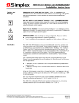
See Figure 15: IDNAC power supply on page 17 and Table on page 17 for the main components of the IDNAC power supply.
Fig 15: IDNAC power supply
Table 12: Main components information
P1 RUI Class A/B jumpers P2 IDNet Class A/B jumper
TB4 Battery connection TB2 IDNAC
P10 AC Power Connection TB3 Aux Relay 1 and 2
J15
DCAI
Zone/Relay Connection
J10 IDNet Loop 2
J7 Zone/Relay J11 IDNet Loop 3
J16 CPU Connection P5 Battery Depleted Jumper
J17 Option Connection P8 1-2 (default) / IDNet card on line
P11 City Circuit Connection
TB1 IDNet Loop 1, Aux Power, RUI Connection
P9
25V Regulator Jumpers 1-2, 3-4
default. Power is fed to the zone/relay card. No jumpers.
Using 4007-9802, 25V Regulator Module

Page 18 579-1102 Rev H
4007ES and 4007ES Hybrid Fire Alarm Systems Installation Manual
5.1 Power supply specifications
The IDNAC Power Supply can supply 4A of 24V power in addition to the base draw of the CPU/power supply cards. The current draw taken from
optional cards, IDNet Devices, Aux Power, and NACs must be subtracted from 4A.
Table 13: 4007ES system current draw
Maximum AC input
2 A at 120 VAC, 50/60 Hz
1 A at 240 VAC, 50/60 Hz
Standby conditions (see Note 1) Current (see Note 1) (Battery Standby 24 V)
No alarms (NACs normal). No IDNet devices connected 180 mA
Add to above for each additional IDNet or IDNAC device in standby 0.8 mA
Total current for fully loaded IDNet or IDNAC channel in standby 431 mA
Alarm conditions (see Note 1) Current (see Note 1) (Battery Alarm 24 V)
IDNAC ON: No IDNet LED On. No IDNet devices connected 185 mA
Add to above for each IDNet device in alarm (see note 2) 1 mA
Add to above for each IDNet LED On (20 maximum IDNet devices LEDs On) 2 mA
Total current for fully loaded IDNet channel in alarm (20 LEDs On) (see note 2) 475 mA
NOTE:
1. Add an additional 9 mA per active auxiliary relay (Alarm or Standby).
2. The IDNAC Alarm current depends on the IDNAC device used. See the relevant device manual for more information on currents.
5.2 IDNAC section overview
The IDNAC power supply has a single SLC for connecting addressable IDNAC devices. The power supply is compatible with TrueAlertES and TrueAlert
Addressable product lines, both multi and fixed candela. The IDNAC output is Class B only. Class A operation requires use of the optional module
4007-9804, IDNAC dual Class A isolator.
The output is duplicated on the terminal block to facilitate T-tapping on the circuit at the panel. EOL resistors are not required.
All wiring is supervised and power-limited.
+ -
IDNAC
+ -
Fig 16: IDNAC terminal
/