Page is loading ...

4905 TrueAlert Isolator +
Installation Instructions
2005, 2006, 2013 Tyco Fire Protection Products. All rights reserved.
Specifications and other information shown were current as of publication and are subject to change without notice.
TYCO, SIMPLEX, and the product names listed in this material are marks and/or registered marks. Unauthorized use is strictly prohibited..
574-769
Rev. C
DO NOT INSTALL ANY SIMPLEX
®
PRODUCT THAT APPEARS DAMAGED. Upon unpacking
your Simplex product, inspect the contents of the carton for shipping damage. If damage is apparent,
immediately file a claim with the carrier and notify an
authorized Simplex Product Supplier.
ELECTRICAL HAZARD - Disconnect electrical field power when making any internal adjustments or
repairs. All repairs should be performed by a representative or authorized agent of your local Simplex
product supplier.
STATIC HAZARD - Static electricity can damage components. Handle as follows:
Ground yourself before opening or installing components.
Prior to installation, keep components wrapped in anti-static material at all times.
FCC RULES AND REGULATIONS – PART 15 — This equipment has been tested and found to comply
with the limits for a Class A digital device, pursuant to Part 15 of the FCC Rules. These limits are designed to
provide reasonable protection against harmful interference when the equipment is operated in a commercial
environment. This equipment generates, uses, and can radiate radio frequency energy and, if not installed and
used in accordance with the instruction manual, may cause harmful interference to radio communications.
Operation of this equipment in a residential area is likely to cause harmful interference in which case the user
will be required to correct the interference at his own expense.
The TrueAlert family of notification appliances provides addressable control and supervision of
individual appliances and circuit wiring. Appliances are operated over a single two-wire notification
appliance circuit (TrueAlert Channel) that allows T-tapping (Class B only). The TrueAlert Isolator
+ Module provides a means of containing the effects of a short circuit on the TrueAlert Channel to a
single segment of wire, as well as an aid in locating stray connections to earth ground. The
TrueAlert Channel can be broken into segments called Virtual NACs (VNACs) in both Class B
and Class A circuit topologies using the TrueAlert Isolator + module to abut segments. TrueAlert
Isolator + Modules operate contact switches through commands received over the 2-wire
TrueAlert circuit from the 4009 TrueAlert Addressable Controller and TrueAlert Power Supply
(TPS). TrueAlert Isolator + modules automatically isolate the short to a single segment of wire,
but require a command from the host panel to restore the connection. Manual control of opening
and closing the contacts is also available through the TrueAlert Power Supply.
The range of possible temperatures under which the TrueAlert Isolator + can function is between
0C (32F) and 49C (120F).
The TrueAlert Isolator + operates normally under non-condensing humidity conditions up to 93%
with relative humidity at 38C (100F).
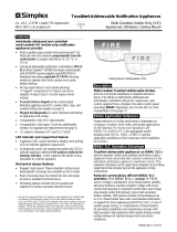
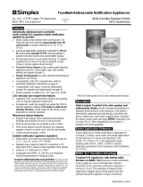
The TrueAlert Isolator + Module has a LED that the TrueAlert Addressable Controller can
command to Flash ON, OFF, or blink when polled. See Figure 1, TrueAlert Isolator + Module.
Note: The TrueAlert Isolator + Module is a faster version of the original TrueAlert Isolator. It is a
100% backwards compatible replacement for the original version. You will not necessarily gain
the enhanced speed benefit of the short isolation unless all your isolators are the new “+” type on
the same TrueAlert Channel. The “+” version can be identified by looking at the silkscreen on the
PCA for “TrueAlert Isolator +” located near the terminal block.
Cautions and
Warnings
Introduction

2
This publication discusses the following topics:
Topic See Page
TrueAlert Isolator + Wiring 2
TrueAlert Isolator + Class B Wiring 3
TrueAlert Isolator + Class A Wiring 4
Mounting the TrueAlert Isolator + Module 5
Setting the TrueAlert Isolator + Module Address 6
Figure 1. TrueAlert Isolator + Module
Warning: Make sure that all power is disconnected before starting the installation.
Caution: Connect Wiring to terminals as shown. Do not loop wires under terminals.
Break wire runs to provide supervision of connections. Do not bring conduit
through the rear of the electrical box. Strip lead insulation to 3/8” maximum.
1. At the electrical box, connect the contractor wire to the PORT 1/PORT 2 (+ and -) terminal of
the TrueAlert Isolator + Module. See figure 2 and 3, TrueAlert Isolator + Class B and A
Wiring.
2. Ensure that correct polarity is maintained across the ports.
3. Ensure that the CKT +’s or -’s are not crossed between ports.
4. Do not loop wires under the terminals.
Installation instructions, Continued Installation instructions, Continued
In this Publication
TrueAlert Isolator +
Wiring

3
EPS IDNAC,
4009 IDNAC
Repeater,
4009 TrueAlert
Addressable
Controller or
TrueAlert
Power Supply
4905-9929 TrueAlert Isolator + Module
TERMINALS ACCEPT
2 WIRES: #12 - #18 AWG
(SEE NOTE 5 in Figure 3)
Non-Isolated
Devices
Isolated
Devices
(non-powered
when isolated)
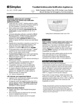
Note:
On any segment of wire protected by one or more Isolator+ modules, limit the wire
resistance to a maximum value of 1.5 ohms for a given line path. The wire resistance
is measured from the Controller’s port to the furthest appliance in the protected
segment. Deviation from this limitation does not guarantee isolation for short-circuits
that are located greater than 1.5 ohms.
Figure 2. TrueAlert Isolator + Class B Wiring
Installation instructions, Continued
TrueAlert Isolator +
Class B Wiring4-769-
01

4
Port 1
Port 2
4905-9929 Isolator Module
Port 1
Port 2
4905-9929 Isolator Module 4905-9929 Isolator Module
Port 2
Port 1
CKT -
CKT +
CKT -
CKT +
CKT +
CKT -
CKT +
CKT -
CKT +
CKT -
CKT +
CKT -
- CLASS A + - CLASS A + - CLASS A +
Notes:
1. Refer to the field wiring diagrams or the installation manual supplied with the
applicable system for detailed circuit wiring information. No more than 6 Isolator +
Modules can be connected at any port.
2. Limit the wire resistance to a maximum value of 1.5 ohms for a closed line path in the
SLC wiring. Deviation from this limitation does not guarantee isolation for short-
circuits that are located greater than 1.5 ohms.
3. Notification Appliances are rated per individual nameplate label.
4. Maintain correct polarity on terminal connections. Do not loop wires under terminals.
5. All circuit wiring connections are supervised and power-limited.
6. Powering the Isolator + Module from an appliance power source less than 17.6 VDC
or greater than 32 VDC may cause permanent damage to the module.
7. The TrueAlert Isolator + Module can be operated through the TrueAlert Addressable
Controller, the TrueAlert-compatible FACP, the 4009 IDNAC Repeater or the EPS
IDNAC.
8. The Isolator + Module counts for 4 unit loads on the TrueAlert Channel. De-rate
alarm load line voltage drop allowance by 0.06 V/amp of alarm current per Isolator +
Module.
9. T-tapping is not allowed for Class A wiring. For Class B wiring, T-tapping is allowed.
Refer to the field wiring diagram for maximum T-tapping length.
10. The TrueAlert Isolator + current draw is 10 mA maximum over its operating range.
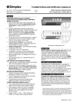
Figure 3. Typical TrueAlert Isolator + Class A Wiring
Installation instructions, Continued
TrueAlert Isolator +
Class A Wiring
4905-9929 TrueAlert
Isolator + Module
4905-9929 TrueAlert
Isolator + Module
4905-9929 TrueAlert
Isolator + Module

5
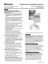
The TrueAlert Isolator + module mounts to the 4-inch square grounded metal electrical box via 2
screws. Box depth is dependent on the number and size of conductors used in a particular
application. The range extends from a minimum 2 1/8” deep box to a 1 1/2” deep box with a
minimum 1 1/2” extension ring.
Caution: Do not bring conduit through the rear of the electrical box.
1. Tighten mounting screws snugly (do not over-tighten).
2. For semi-flush mounting, install the box either flush with the wall or with a maximum ¼-
inch recess.
The TrueAlert Isolator + Module uses terminals to connect to each wire point. Each accepts 2
wires of gauges #12 through #18 AWG. The terminal screws at TB1 accommodate both slotted
and Philips drive.
Refer to the Field Wiring Diagrams, or applicable installation manuals, for detailed information on
maximum wire run distance.
FigureTag FD4-769-02
Grounded Metal Electrical Box,
Electrical box, 4” square (102 mm),
2 1/8” (54 mm) minimum depth,
RACO 232 or equal (by others)
4905-9929 TrueAlert Isolator + Module
4“ Square cover plate,
RACO 752 or equal (by others)
Note: A cover plate (not supplied) is required to complete installation
Figure 4. TrueAlert Isolator + Mounting
Installation instructions, Continued
Mounting the
TrueAlert Isolator +
Module

The True Alert Isolator + has a unique address. Each device’s address is set via an eight-position
DIP switch, as shown in Table 1. See Figure 1 for the general DIP switch location. DIP switch
position 1 is the least significant bit (LSB) and position 8 is the most significant bit (MSB).
Note: DIP Switches 1 through 6 are used to set the possible 63 address codes, DIP
Switches 7 and 8 are not used and are set to “OFF”.
Use a small screwdriver or pen to set the switches, and then write the address on the resealable
label. This information provides an aid in troubleshooting the system.
Notes:
1. The TrueAlert Channel (4009 TrueAlert Addressable NAC Controller or TrueAlert
compatible FACP only) supports address codes 1 through 63.
2. DIP switch in "1" position is "ON" while DIP switch in "0" position is "OFF”.
Table 1. TrueAlert Isolator + Module – DIP Switch Address Chart
0000 1000 0100 1100
0000
0 163248
1000
1 173349
0100
2 183450
1100
3 193551
0010
4 203652
1010
5 213753
0110
6 223854
1110
7 233955
0001
8 244056
1001
9 254157
0101
10 26 42 58
1101
11 27 43 59
0011
12 28 44 60
1011
13 29 45 61
0111
14 30 46 62
15 31 47 63
LSB
MSB
1 2345678
1111
DIP SWITCHES 5 AND 6
DIP
SWITCHES
1 THRU 4
RESERVED FOR
FUTURE USE
NOT USED
ON
OFF
1 = ON 0 = OF
F
DIPSWITCH SHOWN IS
SET AT ADDRESS 7.
Installation instructions, Continued
Setting the TrueAlert
Isolator + Module
Address
574-769
Rev. C
(SET TO OFF)
/