Page is loading ...

4007ES Operator’s Manual
579-1165
Rev. C

2
© 2015- 2016 Tyco Fire Protection Products. All rights reserved. All specifications and other information shown were
current as of document revision date and are subject to change without notice.
TYCO, SIMPLEX, and the product names listed in this material are marks and/or registered marks. Unauthorized use is
strictly prohibited.
Cautions
and Warnings
READ AND SAVE THESE INSTRUCTIONS- Follow the instructions in this installation manual. These instructions
must be followed to avoid damage to this product and associated equipment. Product operation and reliability depend upon
proper installation.
DO NOT INSTALL ANY SIMPLEX® PRODUCT THAT APPEARS DAMAGED- Upon unpacking your Simplex
product, inspect the contents of the carton for shipping damage. If damage is apparent, immediately file a claim with the
carrier and notify an authorized Simplex product supplier.
ELECTRICAL HAZARD - Disconnect electrical field power when making any internal adjustments or repairs. All repairs
should be performed by a representative or authorized agent of your local Simplex product supplier.
STATIC HAZARD - Static electricity can damage components. Handle as follows:
• Ground yourself before opening or installing components.
• Prior to installation, keep components wrapped in anti-static material at all times.
FCC RULES AND REGULATIONS – PART 15 - This equipment has been tested and found to comply with the limits for a Class A digital device
pursuant to Part 15 of the FCC Rules. These limits are designed to provide reasonable protection against harmful interference when the equipment is
operated in a commercial environment. This equipment generates, uses, and can radiate radio frequency energy and, if not installed and used in accor-
dance with the instruction manual, may cause harmful interference to radio communications. Operation of this equipment in a residential area is likely to
cause harmful interference in which case the user will be required to correct the interference at his own expense.
Cautions, Warnings and Copyright

3
4007ES Operator’s Manual (579-1165)
Introduction
The user interface is touchscreen based on 4007-9101 4007ES and 4007-9201 4007ES Hybrid* Fire Alarm Control
Panels (FACP). The various functions of the panel are access-level protected, thus restricting access to sensitive features
to appropriate personnel only.
The 4606-9202 and the 4606-9205 are Color Touchscreen LCD Annunciators for 4007ES panels. They provide remote
annunciation of the FACP status. Access to Annunciator switch functions can be enabled or locked using the keyswitch.
A maximum of six color touchscreen annunciators can be installed on a 4007ES panel. Refer to the Programmers’s
manual, 579-1167, for more information on how to enable/disable the operations on the Color Touchscreen LCD
Annunciator.
* = The user interfaces for the 4007ES and the 4007ES Hybrid FACPs are identical and referred to collectively as 4007ES in this
document.
In this
publication
Reference
Documents
579-1102: 4007ES Installation Manual
579-1167: 4007ES Programmer Manual
579-1110: 4007ES/4007H Service Parts List
579-1172: Color Touchscreen LCD Annunciator Installation Manual
User Interface ............................................... 4 Panel Setup ................................................................18
Alarm Conditions ........................................... 5 Alarm Log ...................................................................20
Supervisory and Trouble Conditions ........... 10 Trouble Log ................................................................21
Main Menu .................................................. 13 Search ........................................................................22
User Access Level ...................................... 14 Diagnostics .................................................................23
System Info ................................................. 16 Report Menu ..............................................................28
Index .......................................................................... 31

4
4007ES Operator’s Manual (579-1165)
User Interface
Overview:
The user interface is used to operate the FACP.
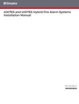
Figure 1. 4007ES User Interface
Figure 2. Color Touchscreen LCD Annunciator User Interface
Table 1. The FACP User Interface is made-up of the following components:
Touchscreen Used as the panel’s input/output interface.
Piezo Emits tones during Alarm, Trouble, Pri2 and Supervisory conditions.
Bi-color User-
Defined LEDs
Associated with the three custom-configured user buttons. The top two LEDs can be either
yellow or red. The bottom LED can be either yellow or green.
Slide-in Labels Used to describe the functions of the user buttons.
Fire LED Indicates a fire alarm when flashing and an acknowledged alarm when steady on.
Priority 2 LED Indicates a Priority 2 condition when flashing and an acknowledged condition when steady on.
Supervisory LED
Indicates a Supervisory condition when flashing and an acknowledged condition when steady on.
Trouble LED Indicates a Trouble state when flashing and acknowledged Trouble when steady on.
Alarm Silence LED Indicates an alarm has been silenced when steady on.
Power LED Indicates AC power is applied to the panel when steady on.
Keyswitch
(Only on the Color Touchscreen LCD Annunciator) Allows interaction with the panel if the key is
used.
Power LED
Alarm Silenced LED
Trouble LED
Priority 2 LED
Supervisory LED
Fire LED
Slide-in LabelsBi-Color User Defined LEDs
Piezo
Touchscreen
Keyswitch
Power LED
Alarm Silenced LED
Trouble LED
Priority 2 LED
Supervisory LED
Fire LED
Slide-in LabelsBi-Color User Defined LEDs
Piezo
Touchscreen
User Interface

5
4007ES Operator’s Manual (579-1165)
Alarm Conditions
Overview:
An alarm condition occurs when an initiating device (such as a manual pull station,
smoke detector, etc.) activates. The panel indicates the presence of the alarm
condition by:
• Displaying messages on the user interface.
• Flashing the Fire or PRI2 LEDs.
• Activating the building’s notification appliances (horns and strobes).
Screen Buttons:
Scroll Up
Scroll Down
Return Accept Decline
Recognizing an Alarm
Condition:
When an alarm condition occurs, the following events occur at the user interface:
Fire PRI2
1. The Fire LED begins to blink
2. The piezo begins to sound a
pulsating tone
3. The user interface displays the
Fire Alarm in System screen,
which shows the list of all the
triggered alarms.
1. The PRI2 LED begins to blink
2. The piezo begins to sound a pulsating tone
3. The user interface displays the PRI2 Alarm in
System screen, which shows the list of all the
triggered alarms.
Note: A zone groups multiple points together, and the Zone Fire and Zone PRI2 Alarms lists dis-
play all the zones where alarm conditions occurred. You can view the points that triggered
the alarms within each zone by pressing on any given zone from the list.
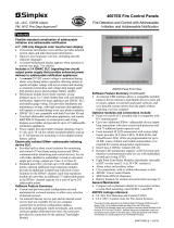
Figure 3. Alarm Condition Screen (Fire Alarm Shown as an Example)
The piezo can be silenced by pressing anywhere on the user interface touchscreen. Until the alarm conditions are
acknowledged, it will re-sound after 1 minute of inactivity at the user interface.
Piezo is emitting a pulsating tone
A list of alarms is displayed
The Fire LED is blinking
Date
Time
Fire Alarm in System
PULL STATION 1
FIRE ALARM
Date
First of 1
MenuAlarm Functions
ACK
1
The number displayed represents the number of alarms
Alarm Conditions

6
4007ES Operator’s Manual (579-1165)
Processing Alarms: There are three actions that may be taken when an alarm condition occurs:
1. Acknowledge an Alarm
2. Silence the Alarm
3. Reset the System
Each step is explained in detail in the rest of this section.
Acknowledge an Alarm: Two types of acknowledging modes can be configured on the panel:
1. Global Acknowledge
All the zones inside the Zone Alarm list are acknowledged at once.
2. Individual Acknowledge
Each zone inside the Zone Alarm list is acknowledged separately.
Global Acknowledge
Tap the ACK button.
Note: Acknowledging an alarm does not silence the horns. You need to silence an alarm as shown in the section “Silence the Alarm”.
Individual Acknowledge
Tap the unacknowledged alarm from the Zone Alarm List.
Note: The alarms that have not been acknowledged display the text “Press to acknowledge” on the top right of the button.
Date
Time
Fire Alarm in System
PULL STATION 1
FIRE ALARM
Date
First of 1
MenuAlarm Functions
ACK
1
Date
Time
Fire Alarm in System
PULL STATION 1
FIRE ALARM
Date
First of 1
MenuAlarm Functions
ACK
1
Alarm Conditions, Continued

7
4007ES Operator’s Manual (579-1165)
Silence the Alarm: Silencing an alarm turns off all the audible notification appliances that are programmed
to turn off when it is pressed.
1. Tap the Alarm Functions button.
2. Press the Alarm Silence button
3. Confirm
WARNING: Ensure the evacuation of the building is completed prior to silencing the alarm.
Date
Time
Fire Alarm in System
PULL STATION 1
FIRE ALARM
Date
First of 1
MenuAlarm Functions
ACK
1
Fire Alarm in System
System Reset
USER
BUTTON 1
USER
BUTTON 2
USER
BUTTON 3
Alarm Silence
Are you sure?
Alarm Conditions, Continued

8
4007ES Operator’s Manual (579-1165)
Reset the System: Resetting the system allows it to return to a normal state after alarm activation.
IMPORTANT: Reset the system only after the source of the alarm is determined
and dealt with.
1, Tap the Alarm Functions button.
2. Tap the System Reset button.
3. Confirm.
Notes: 1. If a zone or device has reset successfully, the user interface returns to its normal display.
2. If a zone or device remains in alarm when you reset the system, the system reset aborts. A message confirming the abort
displays on the user interface.
Date
Time
Fire Alarm in System
PULL STATION 1
FIRE ALARM
Date
First of 1
MenuAlarm Functions
ACK
1
Fire Alarm in System
System Reset
USER
BUTTON 1
USER
BUTTON 2
USER
BUTTON 3
Alarm Silence
Are you sure?
Alarm Conditions, Continued

9
4007ES Operator’s Manual (579-1165)
Viewing the Alarm Condition
Details:
Each alarm condition contains detailed information on the point (or points) that have
triggered it. To access that info:
1. Tap on a desired alarm condition from the Fire Alarm in System screen. That alarm condition can either be a point
or a zone containing a variety of points. A point in alarm is shown as an example.
2. Take the necessary actions, using the buttons available at the point details screen. A pull station point is shown as an
example.
Date
Time
Fire Alarm in System
PULL STATION 1
FIRE ALARM
Date
First of 1
MenuAlarm Functions
ACK
1
M1-1-0
PULL STATION 1
Date
Time
Enable
Disable
M1-1
M1-1 PULL STATION
DEVICE ADDRESS: 2-1 TYPE: ADRPUL
IDNET2 CARD
UNIT NUMBER: 0 RUI NUMBER: LOCAL
---------------------------------------------------------------------
PRIMARY STATUS FIRE ALARM
CURRENT DEVICE CORRECT DEVICE
DEVICE ON-LINE
PHYSICAL STATE ABNORMAL
RAW STATE ABNORMAL
ACTIVE STATE OFF
ARMED STATE ARMED
ENABLED STATE ENABLED
Alarm Conditions, Continued

10
4007ES Operator’s Manual (579-1165)
Supervisory and Trouble
Conditions Overview:
A Supervisory condition indicates a problem with the building’s automatic sprinkler
system or some other system used for the protection of life and property.
A Trouble condition indicates the presence of a circuit break, or a ground, within a
system point, or somewhere between the FACP and one of its points. It can also be
used to indicate a failure in the system that requires attention.
The panel indicates the presence of a Supervisory, or Trouble condition by:
• Displaying messages on the user interface.
• Flashing the Supervisory or Trouble LEDs.
Screen Buttons:
Scroll Up
Scroll Down
Return Accept Decline
Recognizing a Supervisory
and a Trouble Condition:
When an Supervisory or a Trouble event occurs, the following events occur at the user
interface
Supervisory Trouble
1. The Supervisory LED begins to
blink.
2. The piezo begins to sound a
continuous tone.
3. The user interface displays the
Supervisory in System screen,
which shows the list of all the
Supervisory conditions.
1. The Trouble LED begins to blink.
2. The piezo begins to sound a continuous tone.
3. The user interface displays the Trouble in
System screen, which shows the list of all the
Troubles.
Figure 3. Supervisory or Trouble Condition Screen (Trouble Conditions Shown as an Example)
Date
Time
Trouble in System
ACK
5
Alarm Functions Menu
CARD 1, NAC POWER SUPPLY
NAC MISWIRE TROUBLE
Date
First of 5
SYSTEM TIME/DATE INVALID OR NOT SET
ABNORMAL
Date
Most Recent of 5
The piezo can be silenced by pressing anywhere on the user interface touchscreen. Until the Trouble and Supervisory
conditions are acknowledged, it re-sounds after 1 minute of inactivity at the user interface.
Piezo is emitting a continuous tone
The list of Troubles is displayed
The number displayed represents the number of Troubles and Supervisory conditions
The Trouble LED is blinking
Supervisory and Trouble Conditions

11
4007ES Operator’s Manual (579-1165)
Processing Supervisory and
Trouble Conditions:
When a Supervisory or a Trouble event occurs, it needs to be acknowledged and the
cause of the event resolved for the system to return to normal. Two types of
acknowledging modes can be configured on the panel.
1. Global Acknowledge
All the zones inside the Zone Supervisory or Zone Trouble lists are acknowledged at
once.
2. Individual Acknowledge
Each zone inside the Zone Alarm List are acknowledged separately.
Note: A zone groups multiple points together and the Zone Supervisory or Zone Trouble list
displays all the zones where Trouble or Supervisory conditions occurred.
Global Acknowledge
Tap the ACK button.
Individual Acknowledge
Tap the unacknowledged Trouble from the events list.
Note: The Troubles that have not been acknowledged display the text “Press to acknowledge” on the top right of the button.
Date
Time
Trouble in System
ACK
5
Alarm Functions Menu
CARD 1, NAC POWER SUPPLY
NAC MISWIRE TROUBLE
Date
First of 5
SYSTEM TIME/DATE INVALID OR NOT SET
ABNORMAL
Date
Most Recent of 5
Date
Time
Trouble in System
ACK
5
Alarm Functions Menu
CARD 1, NAC POWER SUPPLY
NAC MISWIRE TROUBLE
First of 5
SYSTEM TIME/DATE INVALID OR NOT SET
ABNORMAL
Most Recent of 5
Press to acknowledge
Press to acknowledge
Supervisory and Trouble Conditions, Continued

12
4007ES Operator’s Manual (579-1165)
Viewing the Supervisory and
Trouble Conditions Details:
Each Supervisory or Trouble condition contains detailed information on the point (or
points) that have triggered it. To access that info (Trouble screen is shown as an
example):
1. Tap on a desired Trouble condition from the Trouble in System screen. That Trouble condition can either be a point
or a zone containing a variety of points. A point in Trouble state is shown as an example.
2. Take the necessary actions, using the buttons available at the point details screen. A Time and Date Trouble is used
as an example.
Date
Time
Trouble in System
ACK
5
Alarm Functions Menu
CARD 1, NAC POWER SUPPLY
NAC MISWIRE TROUBLE
First of 5
SYSTEM TIME/DATE INVALID OR NOT SET
ABNORMAL
Most Recent of 5
Press to acknowledge
Press to acknowledge
P58
SYSTEM TIME/DATE WAS NOT SET
Date
Time
On
Off
Time /Date
Trouble Details
Auto
Supervisory and Trouble Conditions, Continued

13
4007ES Operator’s Manual (579-1165)
Main Menu
Overview:
The Main Menu screen displays the functions available at the panel and can be accessed by:
• Tapping anywhere on the touchscreen to remove the screensaver image.
• Tapping the Menu button on the user interface if the user interface is in use.
Screen Buttons:
User Button 1* User Button 2*
User Button 3*
Return Button
* User Buttons can be assigned to custom panel functions. Each function can be assigned to a
task, such as Manual evacuation or City Disconnect. User buttons that have not been assigned a
function do not appear on the user interface.
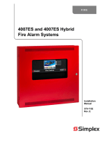
Figure 4. Main Menu Screen
Main Menu Icons Description Page
System Info Use the System Info function to obtain detailed information regarding the panel and its
components.
16
Panel Setup Use the Panel Setup function to modify the configuration of the basic components. 18
Alarm Log The Alarm Log screen contains the list of alarms that the panel has received. 20
Trouble Log The Trouble Log screen contains the list of Troubles that the panel has received. 21
Search Use the Search screen to look for any configured point on the system controlled by the
panel.
22
System Reset Tap the System Reset button to reset all devices in alarm and clear all acknowledged
Alarms, Troubles and Supervisory conditions.
8
Hardware Reset
Tap the Hardware Reset button to re-initialize the state of certain hardware
components. A hardware reset is typically used to reset Class A Troubles after the
problem causing the Trouble is resolved.
22
Diagnostics Use the Diagnostics function to run tests on the panel and the connected devices. 23
User Access Level Tap the User Access Level button to access the login screen. From this screen, the
user can log into the panel with a desired access level, or log out of the access level
that he is currently in.
14
Lamp Test
Tap the Lamp Test button to light all 9 LEDs on the front panel for 5 seconds. The three
dual-colored LEDs blink alternately. The touch screen alternates between red, green
and blue.
13
Report Menu Tap the Report Menu button to generate various types of reports on the system points. 27
USER
BUTTON 1
USER
BUTTON 2
USER
BUTTON 3
Main Menu
System Info Panel Setup Alarm Log Trouble Log
USER
BUTTON 1
USER
BUTTON 2
USER
BUTTON 3
Search System Reset
Hardware
Reset
Diagnostics
User Access
Level
Lamp Test
Report Menu
Date
Time
Main Menu

14
4007ES Operator’s Manual (579-1165)
User Access Level
Overview:
Tap the User Access Level button to access the login screen, where the user can log
in to the panel with a desired access level, or log out of the current access level.
Notes: 1. Four access levels can be used to log in to the panel, with the lowest, User Access
Level 1, being the default.
2. Only some functions are available at each access level. The User Access Level
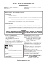
Chart (Figure 6) shows functions with associated default user access levels.
3. The ES Panel Programmer can be used to modify default user access levels for each
function, or set user access level passcodes. Refer to document 579-1167: 4007ES
Panel Programmer’s Manual for more details.
Screen Buttons:
Erase
Accept Return
Figure 5. User Access Level Screen
User Access Level
Current Access Level: 1
Enter Passcode
Logout
1
ABC
2
DEF
3
JKL
5
TUV
8
WXYZ
9
0
GHI
4
MNO
6
PQRS
7
Date
Time
Logout:
Tap the Log Out button to log out of the current user access level. Once logged out, the user is
returned to Access Level 1.
Continued on next page
Logout
User Access Level

15
4007ES Operator’s Manual (579-1165)
Figure 6. User Access Level Chart
System Info
1
Panel Setup
2
Alarm Log
1
Trouble Log
1
Search
1
System Reset
1
Hardware Reset
2
Diagnostics
2
User Access
Level
1
Lamp Test
1
Report Menu
1
User Buttons 1,2 3
***
Main Menu
1
Card
Revisions
1
Software
Revisions
1
Panel Serial
Number
1
Card Status
1
Swap Config
2
Set Time/Date
2
Touchscreen
Calibration
2
Mass Storage
1
HW Reset
2
Restart
4
Walktest
3
Cfig Download
3
Earth Fault Search
3
Earth Fault Latch
2
NAC Miswire Test
3
Duplicate Device Search
3
Weak Answer Search
3
TrueAlert Test
3
TrueAlert NAC Test
3
CO Algorithms
3
Install Mode
2
AlarmLog
1
TroubleLog
1
TrueAlarm
Status
1
TrueAlarm
Service
1
TrueAlert
NAC Test
1
TrueAlert Status
1
TrueAlarm CO
1
Active List
1
Verification Tally
1
TrueAlert
Self-Test
1
Main Menu
1
Function Name
Default Access Level
Show Alternate
Config Version
2
Use Alternate
Config
2
Location
3
IDNet
3
Last Result
3
TrueAlert ES
Self-Test?
3
TrueAlert Device LEDs Test?
3
TrueAlert Device Test Mode?
3
TrueAlert Silent Test Mode?
3
IViewMod
2
IAddMiss
3
IAddOpens
3
IRemvNorm
3
IRemvAll
3
Log Menu
1
*** = Default Access Level Configured with the ES Panel Programmer
Clear
3
Clear
3
Select Item
1
Calibrate
2
Clear
2
Next Group
3
Prev Group
3
Select Item
3
Enable
3
Enable All
3
Disable
3
Revert
3
Off
3
On
3
ViewRaw
2
All
3
Single
3
Off
3
On
3
Off
3
On
3
All
3
Single
3
Off
3
On
3
ALL
1
LAST
1
PrtInstal
1
LAST
1
ALL
1
Run Self-Test?
3
View Test Results?
3
View Last Test Results?
3
View All Test Results?
3
Off
3
On
3
Off
3
On
3
Off
3
On
3
System
Upgrade
1
Job
Backup
1
Save
Reports
1
Upgrade
Status
1
SnapShot
Recovery
1
Eject USB
1
Piezo Silence
3
Off
3
On
3
NetDiag
4
User Access Level, Continued

16
4007ES Operator’s Manual (579-1165)
System Info
Overview:
Use the System Info function to obtain detailed information regarding the panel and its
components. Tap on a menu icon to access that option’s main screen. Refer to Figure 6 for
access levels required to use each option inside the System Info screen.
Screen Buttons:
Scroll Up
Scroll down
Accept
Return
Figure 7. System Info Screen
System Info
Card
Revisions
Software
Revisions
Panel Serial
Number
Card
Status
USER
BUTTON 1
USER
BUTTON 2
USER
BUTTON 3
Date
Time
System
Files Info
IP Info
Card Revisions:
Tap the Card Revisions button to see a list of all the cards (modules) installed in the panel.
Software Revisions:
Tap the Software Revisions button to see the latest master revisions loaded on the panel.
Panel Serial Number:
Tap the Serial Number button to see the serial number of the panel.
Card Status:
Tap the Card Status button to see the status of the different cards installed in the panel.
Continued on next page
Card Revision
Information
Appears Here
Card Revisions
Date
Time
Software Revision
Information
Appears Here
Software Revisions
Date
Time
Serial Number
Appears Here
Panel Serial Number
Date
Time
Card Status
Appears Here
Select Card for Status
Date
Time
System Info

17
4007ES Operator’s Manual (579-1165)
System Files Info:
Tap t h e System Files Info button to see the latest master revisions loaded on
the Remote Annunciator.
IP Info:
Tap the IP Info button to see the IP and the MAC address of the 4007ES
panel.
BOOTLOADER REV: 1.01.00.03
KERNEL REV: 1.01.00.10
FILESYSTEM REV: 1.01.01.15
PANELUI: 1.01.02.16
System Files Info
Date
Time
IP ADDRESS: 192.168.1.150
HARDWARE ADDRESS:
00:08:bd:01:dc:43
IP Info
Date
Time
System Info, Continued

18
4007ES Operator’s Manual (579-1165)
Panel Setup Overview: Use the Panel Setup function to modify the configuration of the basic panel components.
Tap on a menu icon to access that option’s main screen. Refer to Figure 6 for access levels
required to use each option inside the Panel Setup screen.
Screen Buttons:
Scroll Up
Scroll down
Accept
Return
Figure 8. Panel Setup Screen
Panel Setup
Swap Config
Set Time/Date
Touchscreen
Calibration
Mass
Storage
USER
BUTTON 1
USER
BUTTON 2
USER
BUTTON 3
Date
Time
Swap Config:
Tap the Swap Config button to access the functions below. These
functions allow roll back to the previous versions of the panel firmware.
• Show Alternate Config Version: Tap this button to display the
previous version of the panel
firmware.
• Use Alternate Config Version: Tap this button to install the
previous version of the panel
firmware.
Set Time/Date:
Tap the Set Time/Date button to access the screen where the date and
time displayed at the panel can be updated:
1. Press the button that corresponds to either day, month, year, hour,
minute or second.
2. Enter a new value using the touchscreen keypad.
3. Repeat steps 1 and 2 for the date and time values that remain.
4. Press the Accept button for the new date and time to take effect
immediately.
Touchscreen Calibration:
Tap the Touchscreen Calibration button to access the calibration
screen and adjust the sensitivity of the user interface touchscreen.
Follow these steps to adjust:
1. Increase or decrease the touchscreen sensitivity by using the Scroll
Up and Scroll Down buttons.
2. Tap the Calibrate button and then tap the “+” signs that appear to
adjust the precision of the touchscreen pressure sensors.
3. Return to the System Menu screen.
Continued on next page
Swap Config
Show Alternate
Config Version
Use Alternate
Config
USER
BUTTON 1
USER
BUTTON 2
USER
BUTTON 3
Date
Time
Day Month
Year
Hrs Mins
Sec
::
12
3
4
56
7
89
0
Panel Setup
0101 01
01 01
01
Date
Time
Calibrate
Clear
Sensitivity
3x
Panel Setup
Date
Time
Panel Setup

19
4007ES Operator’s Manual (579-1165)
Mass Storage:
Tap the Mass Storage button to access the functions listed below. The
USB key must be inserted in the USB Port slot of the 4007 CPU Card
for the Mass Storage button to work.
• Job Backup: Tap this button to save the job currently loaded on
the panel to the USB key.
• Save Reports: Tap this button to save reports to the USB key.
• Upgrade Status: Tap this button to see the progress of the
software upgrades.
• SnapShot Recovery: Tap this button before doing a system
upgrade to copy the software types currently loaded on the panel
to the USB key.
To upload these software types back on the panel, re-insert the
USB key in the USB Port of the 4007 CPU Card and tap the
SnapShot Recovery button.
• Eject USB: Tap this button to safely remove the USB from the
panel.
With a USB thumb drive inserted, tap the System Upgrade button to
open the System Upgrade screen which contains a list of all the panel
software types and their current revisions. The software type in bold and
colored green indicates that its more recent version can be loaded on
the panel.
Note: The System Upgrade screen is launched by default when the USB key is
inserted in the USB Port of the 4007 CPU Card.
• Use the Select All button to select all of the software types listed
in the table.
• Use the Change Job button to load a new job on the panel.
• Use the Refresh Reset button to refresh the software type list.
• Use the Process Upgrade button to proceed with the change.
System
Upgrade
Mass Storage
Job
Backup
Save
Reports
Upgrade
Status
SnapShot
Recovery
Eject USB
Select
All
System Upgrade
Change
Job
Refresh
Reset
Process
Upgrade
0 of 10 files selected
CARD
SOFTWARE TYPE
REVISION
0
0
0
0
0
4007H1LN
Main App
Bootloader
Kernel
Filesystem
1
302.03.02.02
1.00.00.14
1.00.00.11
1.00.00.20
Panel Setup, Continued

20
4007ES Operator’s Manual (579-1165)
Alarm Log Overview: The Alarm Log screen contains a list of alarms that the panel has received. Refer to Figure
6 for access levels required for each option inside the Alarm Log screen.
Screen Buttons:
Scroll Up
Scroll down
Return
Figure 9. Alarm Log Screen
FIRE ALARM IN SYSTEM
Menu
Date
Time
First of 1 M1-30-0 Date Time
M1-30-0
PULL STATION FIRE ALARM
Alarm
Functions
ACK
1
Clear:
IMPORTANT: Use the Clear button only after the alarms have been
investigated.
Tap the Clear button to erase all entries in the Alarm Logs screen.
Clear
Alarm Log
/