Page is loading ...

579-1019 Rev M
4009 IDNAC Repeater Installation Instructions
*05791019M*
Cautions, Warnings, and Regulatory Information
READ AND SAVE THESE INSTRUCTIONS Follow the instructions in this installation manual. These instructions must be followed to avoid damage to
this product and associated equipment. Product operation and reliability depend upon proper installation.
DO NOT INSTALL ANY SIMPLEX™ PRODUCT THAT APPEARS DAMAGED Upon unpacking your Simplex product, inspect the
contents of the carton for shipping damage. If damage is apparent, immediately file a claim with the carrier and notify an authorized
Simplex product supplier.
ELECTRICAL HAZARD Disconnect electrical field power when making any internal adjustments or repairs. All repairs should be
performed by a representative or an authorized agent of your local Simplex product supplier.
STATIC HAZARD Static electricity can damage components. Handle as follows:
• Ground yourself before opening or installing components.
• Prior to installation, keep components wrapped in anti-static material at all times.
SULFURIC ACID WARNING Battery contains sulfuric acid, which can cause severe burns to the skin and eyes and can destroy
fabric. Replace any leaking or damaged battery while wearing appropriate protective gear. If you come in contact with sulfuric acid,
immediately flush skin or eyes with water for 15 minutes and seek immediate medical attention.
Introduction
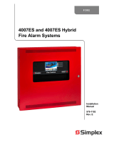
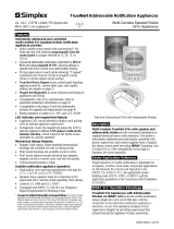
The 4009 IDNAC Repeater is a TrueAlertES Addressable device that extends the maximum wiring distance supported by the IDNAC Signaling Line
Circuit (SLC).
The IDNAC Repeater is compatible with Fire Alarm Control Panels (FACPs) that use the Extended Power Supply (EPS and EPS+).
The following lists IDNAC Repeater models:
• 4009-9601 120 V/240 V Platinum UL/ULC
• 4009-9602 120 V/240 V Red UL/ULC
• 4009-9601 BA 120 V/240 V Platinum UL/ULC assembled in USA.
• 4009-9602 BA 120 V/240 V Red UL/ULC assembled in USA
CAUTION
DISCONNECT
BEFORE
BATTER
A.C. POWER
Y AND
SERVICING
B
Fig 1: 4009 IDNAC Repeater

Page 2 579-1019 Rev M
4009 IDNAC Repeater Installation Instructions
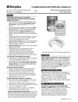
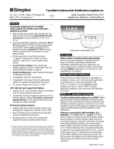
Card layout and Specifications
Card layout
2 31 7654 8
IDNAC OUT
+ +
SHLD
- -
IDNAC IN
AUX OUTPUT
+ +
SHLD
- -
+
-
TB1
+
-
TB2
AC POWER
BATTERY INPUT
TRBL A
TRBL B
TRBL C
COMM
TRBL D
IDNAC In AUX OutputIDNAC Out
Battery
Input
Block
Address
Wiring
Mode
LEDs
Jumpers
Class A
Adapter
Connectors
AC Connector
Fuse
Trouble
Scroll
Switch
Low Battery
Disconnect
Jumper
J4
IDNAC IN line
termination Jumper
100%
Fig 2: Card Layout
Card specifications
Table 1: Card specifications
Operating conditions
32°F - 120°F (0°C-49°C)
Up to 93% relative humidity at 90°F (32°C), non-condensing
120 V, 50/60 HZ, 2.5 A
AC Input specifications
240 V, 50 HZ, 1.25 A
Standby: 70 mA plus 0.8 mA for an IDNAC device plus Aux Output current
DC Input specifications
(battery standby)
Alarm: 96 mA plus 1.37XSLC Load Current plus 1.37 X Aux Output Current. (4.5A maximum
with 3A IDNAC SLC load and 200mA Aux Output load)
IDNAC Input specification 1 address, 4 unit loads
Voltage: 29 V special application
IDNAC Output specification
Power: 3 A max.
Voltage: 29V DC Nominal with AC present or when powered from batteries with system
in Alarm or 24 V DC nominal when powered from batteries with system in Standby
mode. Special Application. Aux Loads include 4603-9101 Annunciator, 4100-96xx series
Annunciators, and 4090 series of IDNet ZAMs and IAMs
Electrical specifications
Aux Output specification
Power: 0.2 A max. @ 29 V
Earth fault Earth fault detection is 10 k minimum to any circuit
Charges up to 25 Ah sealed lead-acid batteries connected to the power supply
High Voltage Internal battery charger Output: 27.6 VInternal battery charger
Output Current Limit: 1.3 A

Page 3 579-1019 Rev M
4009 IDNAC Repeater Installation Instructions
Mounting
The 4009 IDNAC Repeater card arrives pre-installed in a stand-alone cabinet. The cabinet measures W 16.5 inches x H 13.75 inches x D 4.5 inches. It is
available in red, and platinum.
Preparing the cabinet
To prepare the Repeater cabinet for mounting, do the following:
1. Carefully remove the Repeater cabinet and contents from the shipping box and lay the cabinet on a flat and solid surface.
2. Prepare the cabinet in order to be able to safely pierce the conduit/service entrances required.
a. Disconnect the AC harness.
b. Use a screw driver to loosen the 4 screws retaining the Repeater assembly.
c. Set the Repeater assembly aside in a safe dry place.
3. Pierce the required conduit and service entrances. It is recommended that the conduit entrance for the AC power be placed at the bottom right
side of the cabinet.
4. Return the Repeater assembly to the cabinet and tighten the hardware.
5. Reconnect the AC harness.
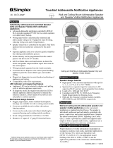
Mounting the repeater
Danger - High Electrocution Risk. Do not remove the protective casings that are pre-installed on the card. They cover
High Voltage zones that present a high electrocution risk.
To mount the Repeater, complete the following steps:
1. Locate the place the Repeater will be installed. To do this, consult the following guidelines:
1. - There must be a clear space of at least 1000 mm in front of the Repeater to provide access for maintenance and testing.
- The top of the cabinet must not be more than 2400 mm above the finished floor level.
- The Repeater must be located in an area that is compatible with it’s operation conditions.
2. Using the Repeater as a template, mark the wall through the tear drop knock out at the top of the Repeater cabinet and through the two holes at
the base of the cabinet.
3. Pierce the four holes.
4. Insert the appropriate hardware, into the top two holes, leaving a 1/8 inch (3.175 mm) gap between the screw head and the wall.
5. Align the tear drop hole in the back of the Repeater with the protruding screws.
6. Hang the repeater on the protruding screws.
7. Insert the appropriate hardware into the two holes at the base of the Repeater.
8. Install the batteries, see Installing the batteries for instructions.
Adaptor Card
Optional Class A
Protective
Casing
Batteries
4009 IDNAC
Repeater Card
AC Harness
Insert Hardware
100%
Fig 3: Mounting the 4009 Repeater cabinet

Page 4 579-1019 Rev M
4009 IDNAC Repeater Installation Instructions
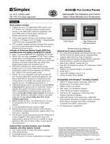
Installing the batteries
The Repeater cabinet is built to accommodate two 12.7 AH batteries.
To safely install the batteries in the Repeater Cabinet using the battery harness, complete the following steps:
1. Place both batteries to the left side on the bottom of the cabinet.
2. Connect the positive terminal of the left battery to the positive battery input on the Repeater using the red cable.
3. Connect the negative terminal of the right battery to the negative battery input on the Repeater using the black cable.
4. Connect the two remaining battery terminals using the white jumper cable, to join the two batteries.
Negative
Jumper
Positive
Battery Input
100%
Fig 4: Installing the batteries

Page 5 579-1019 Rev M
4009 IDNAC Repeater Installation Instructions
Connecting the Repeater to the AC
The Repeater connects to the building AC through the AC terminal block located on the lower right of the Repeater.
IMPORTANT: Ensure that the Power to the circuit is off before proceeding
To connect the repeater to the building AC, complete the following steps:
1. Loosen the screws securing the AC cover.
2. Slide off the cover.
3. Bring the AC wiring in through the conduit entrance on the lower right side of the Repeater cabinet.
4. Connect building AC to the terminal block. The ground wire can be secured under the AC cover screws.
5. Place the AC cover back over the terminal block and tighten the screws.
1
2
Ground
100%
Fig 5: Connecting the Repeater to the AC
NOTE: Wire the Non-Power-Limited wiring only in the shaded areas. This includes AC input and battery connections. All other wiring is Power-
Limited. Maintain at least ¼-inch spacing between all Power-Limited and Non-Power-Limited wiring.
100%
Fig 6: Non-Power-Limited Zone

Page 6 579-1019 Rev M
4009 IDNAC Repeater Installation Instructions
Configurations
Setting the address
The Repeater has a unique address that is set with an eight-position DIP switch (SW2). Set the dip switch according to the address assigned in the
panel ES Programmer job. See Adding the Repeater to the ES Programmer on page 17 for more information.
To set the dip switches, complete the following steps:
1. Retrieve the assigned address in the ES Programmer.
2. Use a non marking tool to set the switches to the address.
3. Record the set address.
NOTE: DIP switch position 8 is not used and must be set to OFF.
1 THROUGH 4
NOT USED
64 80 96 112
65 81 97 113
66 82 98 114
67 83 99 115
68 84 100 116
69 85 101 117
70 86 102 118
71 87 103 119
72 88 104 120
73 89 105 121
74 90 106 122
75 91 107 123
76 92 108 124
77 93 109 125
78 94 110 126
79 95 111 127
0 16 32 48
1 17 33 49
2 18 34 50
3 19 35 51
4 20 36 52
5 21 37 53
6 22 38 54
7 23 39 55
8 24 40 56
9 25 41 57
10 26 42 58
11 27 43 59
12 28 44 60
13 29 45 61
14 30 46 62
15 31 47 63
DIP SWITCHES 5
THROUGH 7
100%
Fig 7: Card addresses
Battery Disconnect Jumper
Use Jumper J3 to select Low Battery operation. The Jumper operates as follows:
• Jumper in the right position (pins 2-3) causes panel shutdown when the batteries are depleted.
• Jumper in the left position (pins 1-2) enables the panel to continue operating.
For S527 compliance, the Jumper must be installed to the right position of J3.
NOTE: When the Jumper is set to pins 2-3, the Repeater will not power-up from the battery.
321
J3
Shut Down
When Depleted
Continue Operation
When Depleted
100%
Fig 8: Battery Disconnect
Jumper positions
Wiring Jumpers
Use Jumpers J1 and J2 to configure the wiring. Set the jumper according to the wiring configuration. Consult the following information when setting the
Jumper:
For local Class B wiring:
Set the Jumper to the Local setting, jumper position 1-2.
For a local Class A* loop:
To create a Class A local loop off of the repeater set the jumper to the Local setting, Jumper position 1-2.

Page 7 579-1019 Rev M
4009 IDNAC Repeater Installation Instructions
3
21
Class A Ext
Local
100%
Fig 9: Wiring
Jumpers
For an extended Class A* loop:
To make the Repeater part of a Class A loop extending from a DCAI ** set the Jumper to the Class A Ext setting, jumper position 2-3.
* The Class A Adapter card must be installed on the repeater in order to use Class A wiring. The wiring jumper setting on the Class A Adapter card
must be identical to the jumper setting on the repeater. Consult the Class A Adapter manual 579-1080 for more information.
**Consult the DCAI manual 579-1029 for more information.
IDNAC IN, Built-in Line Termination Jumper, P10 Connector
This jumper is located on the main PCB at header P10. It is factory configured for OFF across P10 pins 1 and 2. It must remain in that position for
standard operation.
IIDNADNAC INC IN
++ ++
--
--
BTB1B1
CACAAC POWERAC POWERREWOP REWOP
IIDNACDNAC OUT OUT
++ ++
-- --
1
2
3
1 2 3
1 2 3
100%
Fig 10: Wiring Jumper location, shown with a Class A adapter
Wiring overview
The Repeater doubles the EPS SLC maximum wiring distance. Wire the Repeater in either a Class A or Class B wiring configuration.
Repeater specific wiring guidelines
• A Repeater cannot be wired directly into another repeater.
• Only one Repeater can be wired as part of a Class A Loop.
• In a Class B wiring configuration using T-Tap connectors, an SLC can support up to five wiring branches that each include a Repeater.
NOTE: The Repeater does not increase the maximum number of devices supported on the IDNAC channel. The total number of devices on a
channel includes all devices present before and after the repeaters.
General wiring guidelines
• Ensure conductors test free of all grounds.
• All wiring must be done using copper conductors only, unless noted otherwise.
• The required wiring is unshielded Twisted Pair. This wiring must have a capacitive rating of less than 60pf/ft and minimum three twists (turns) per
foot.
• If shielded wire is used, the following conditions apply:
• -Ensure metallic continuity of the shield is maintained throughout the entire cable length.
-Ensure the entire length of the cable has a resistance greater than 1 megohm to earthground.
• In areas of high lightning activity, or in areas that have large power surges, use the 2081-9027 Transient Suppressor on monitor points.
• Do not run wires through elevator shafts.
• When splicing is used, ensure all spliced connections are either soldered with resin-core solder, crimped in metal sleeves, or
• encapsulated with an epoxy resin. When soldering, or crimped metal sleeves are used, insulate the junction with a high-grade electrical tape that is as
sound as the original insulating jacket. If shielded wiring is used, maintain shield continuity throughout.
• Provide a system ground for earth detection and lightning protection devices. This connection must comply with approved earth detection per
NFPA780.

Page 8 579-1019 Rev M
4009 IDNAC Repeater Installation Instructions
• Only system wiring can be run together in the same conduit.
• Ensure underground wiring is free of all water.
Device wiring guidelines
Consult the following guidelines for devices before you begin the field wiring:
• Only IDNAC devices and other compatible devices are permitted on the SLCs. Consult Compatible devices on page 18 for a list of compatible
devices.
• A maximum of six isolators between any appliance and SLC terminals is permitted. A maximum of 12 isolators for each SLC is permitted.
• A maximum of 30 devices connected directly to any isolator terminal pair is permitted.
• All wiring must be 20 AWG to 12 AWG.
• All wiring must be supervised and power-limited.
• A maximum alarm current of 3 A is permitted.
NOTE: In a Class A extension wiring configuration, the maximum loop current is limited to 3 A. In this configuration, the repeater extends
the wiring distance but does not increase the current available for the devices.
• The maximum cable load is 10,000 feet (3,048 m) per channel. The maximum wire length from the Repeater to any device is 4,000 feet (1219 m).
• The nominal voltage rating is 29 VDC.
• Follow the IDNAC Speaker Wiring Application Guidelines in document 579-1015: EPS Installation Instructions for TrueAlert ES Speaker and S/V
appliances.
Installing ferrite beads
A ferrite bead must be installed on all wiring. To install the ferrite bead, do the following:
1. Loop the wire once though the ferrite bead close to the Repeater field wiring terminals for lowest radiated emissions before the wires leave the
box. Do not loop the ground wire on the AC wiring or the shield wire on shielded cables through the ferrite bead.
2. Secure the ferrite bead with the provided cable ties.
Loop
pattern
Cable ties
Ferrite
Bead
100%
Fig 11: Ferrite Bead Installation
Wiring length tables
Use the following tables to calculate the maximum wiring length starting from the Repeater.
NOTE: Use Table on page 9in place of Table on page 9 for TrueAlertES Speakers and Speaker/Visible appliances.
The maximum wiring length is the shorter of the distance limits calculated by alarm current voltage drop, or by reaching the communications distance
limit.
Table 2: UTP wiring limit based on alarm current
Local and extended loop Class A wiring: Total loop length from the Repeater
Local Class B wiring: distance to the last appliance
Alarm current
20 AWG
18
AWG
16
AWG
14
AWG
12
AWG
0.050 4000 ft 4000 ft 4000 ft 4000 ft 4000 ft
0.100 2644 ft 4000 ft 4000 ft 4000 ft 4000 ft
0.150 1763 ft 2802 ft 4000 ft 4000 ft 4000 ft
0.200 1322 ft 2102 ft 3342 4000 ft 4000 ft
0.250 1058 ft 1681 ft 2674 ft 4000 ft 4000 ft
0.300 881 ft 1401 ft 2228 ft 3542 ft 4000 ft
0.350 755 ft 1201 ft 1910 ft 3036 ft 4000 ft
0.400 661 ft 1051 ft 1671 ft 2657 ft 4000 ft
0.450 588 ft 934 ft 1485 ft 2362 ft 3756
0.500 529 ft 841 ft 1337 ft 2125 ft 3380
0.750 353 ft 560 ft 891 ft 1417 ft 2254 ft
1.000 264 ft 420 ft 668 ft 1063 ft 1690 ft
1.250 212 ft 336 ft 535 ft 850 ft 1352 ft
1.500 176 ft 280 ft 446 ft 708 ft 1127 ft
1.750 151 ft 240 ft 382 ft 607 ft 966 ft

Page 9 579-1019 Rev M
4009 IDNAC Repeater Installation Instructions
Table 2: UTP wiring limit based on alarm current
2.000 132 ft 210 ft 334 ft 531 ft 845 ft
2.250 118 ft 187 ft 297 ft 472 ft 751 ft
2.500 106 ft 168 ft 267 ft 425 ft 676 ft
2.750 96 ft 153 ft 243 ft 386 ft 615 ft
3.000 88 ft 140 ft 223 ft 354 ft 563 ft
Wiring distance must not exceed 4000 ft
Table 3: UTP wiring limit based on communication
Local and extended loop Class A wiring: Total loop length from the Repeater
Local Class B wiring:
Distance to the Last ApplianceLine Impedance (Ohms) Devices
20
AWG
18
AWG
16
AWG
14
AWG
12
AWG
14.54 1 1252 ft 2038 ft 3241 ft 4000 ft 4000 ft
12.96 5 1142 ft 1815 ft 2887 ft 4000 ft 4000 ft
11.38 10 1003 ft 1595 ft 2536 ft 4000 ft 4000 ft
10.14 15 893 ft 1420 ft 2258 ft 3590 ft 4000 ft
9.12 20 804 ft 1278 ft 2033 ft 3231ft 4000 ft
8.28 25 730 ft 1160 ft 1845 ft 2934 ft 4000 ft
7.58 30 668 ft 1061 ft 1688 ft 2683 ft 4000 ft
6.97 35 614 ft 977 ft 1553 ft 2469 ft 3928 ft
6.45 40 568 ft 904 ft 1437 ft 2285 ft 3634 ft
6.00 45 528 ft 840 ft 1336 ft 2124 ft 3378 ft
5.60 50 493 ft 784 ft 1247 ft 1982 ft 3152 ft
5.24 55 462 ft 734 ft 1168 ft 1856 ft 2952 ft
4.92 60 434 ft 690 ft 1097 ft 1744 ft 2774 ft
4.75 63 419 ft 665 ft 1058 ft 1682 ft 2675 ft
4.64 65 409 ft 650 ft 1034 ft 1643 ft 2613 ft
4.38 70 386 ft 614 ft 976 ft 1552 ft 2468 ft
4.15 75 366 ft 581 ft 924 ft 1469 ft 2337 ft
3.94 80 347 ft 551 ft 877 ft 1394 ft 2217 ft
3.74 85 330 ft 524 ft 833 ft 1325 ft 2107 ft
3.56 90 314 ft 499 ft 794 ft 1262 ft 2006 ft
3.40 95 299 ft 476 ft 757 ft 1203 ft 1913 ft
3.24 100 286 ft 454 ft 723 ft 1149 ft 1827 ft
3.10 105 273 ft 435 ft 691 ft 1099 ft 1748 ft
2.97 110 262 ft 416 ft 662 ft 1052 ft 1673 ft
2.85 115 251 ft 399 ft 634 ft 1009 ft 1604 ft
2.73 120 241 ft 383 ft 609 ft 968 ft 1539 ft
2.58 127 228 ft 362 ft 576 ft 915 ft 1456 ft
Wiring distance must not exceed 4000 ft
Table 4: Ohms per 1000 ft
Gage Ohms/1000 ft
20 AWG 11.347
18 AWG 7.137
16 AWG 4.488
14 AWG 2.8230
12 AWG 1.7750
NOTE: Although the required wire for IDNAC circuits is twisted pair (controlled impedance) wiring, in some applications it may be
advantageous to use existing wiring that is not twisted pair. This is only permitted if both conductors of the IDNAC circuit reside in the same
metal conduit, and only under certain conditions. Check with your local sales office before using any wiring that is not twisted pair.

Page 10 579-1019 Rev M
4009 IDNAC Repeater Installation Instructions
Table 5: UTP wiring limit for speaker and S/V devices based on communication
Distance to the last appliance
Devices
20 AWG 18 AWG 16 AWG 14 AWG 12 AWG
1 1218 ft 1936 ft 3079 ft 4000 ft 4000 ft
5 1028 ft 1634 ft 2599 ft 4000 ft 4000 ft
10 853 ft 1356 ft 2156ft 3428 ft 4000 ft
15 715 ft 1137 ft 1807 ft 2873 ft 4000 ft
20 603 ft 959 ft 1525 ft 2424 ft 3855 ft
25 548 ft 871 ft 1385 ft 2201 ft 3500 ft
30 501 ft 797 ft 1266 ft 2013 ft 3201 ft
35 461 ft 733 ft 1165 ft 1853 ft 2946 ft
40 427 ft 678 ft 1078 ft 1714 ft 2726 ft
45 397 ft 631 ft 1002 ft 1593 ft 2534 ft
50 370 ft 588 ft 935 ft 1487 ft 2365 ft
55 347 ft 551 ft 876 ft 1393 ft 2215 ft
60 326 ft 518 ft 823 ft 1308 ft 2081 ft
63 314 ft 500 ft 794 ft 1262 ft 2007 ft
65 307 ft 488 ft 776 ft 1233 ft 1960 ft
70 290 ft 461 ft 733 ft 1165 ft 1852 ft
75 275 ft 436 ft 694 ft 1103 ft 1753 ft
80 261 ft 414 ft 658 ft 1046 ft 1663 ft
85 248 ft 394 ft 626 ft 994 ft 1581 ft
90 236 ft 375 ft 596 ft 947 ft 1505 ft
95 225 ft 357 ft 568 ft 903 ft 1436 ft
100 215 ft 341 ft 543 ft 862 ft 1371 ft
105 206 ft 326 ft 519 ft 825 ft 1311 ft
110 197 ft 313 ft 497 ft 790 ft 1256 ft
115 189 ft 300 ft 476 ft 757 ft 1204 ft
120 181 ft 288 ft 457 ft 726 ft 1155 ft
127 171 ft 272 ft 432 ft 687 ft 1092 ft
Wiring distances must not exceed 4000 feet (1219.2 meters)

Page 11 579-1019 Rev M
4009 IDNAC Repeater Installation Instructions
Connecting Local Class B wired appliances
To connect the Repeater to the EPS or to an appliance using local Class B wiring, complete the following steps:
1. Route the wire from the + and the - outputs to the Repeater IDNAC IN terminal block.
2. Route the wire from the + and the - outputs on the Repeater IDNAC OUT terminal blocks to the corresponding inputs on a peripheral notification
appliance.
3. Route wire from the first appliance to the next one. T tapping is allowed. Repeat this for each appliance.
NOTE:
1. Notification appliances are rated for each individual name plate label. Maintain correct polarity on terminal connections. Do not loop wires under
terminals.
2. Each IDNAC+ and - terminal is rated for two identical wires, enabling up to four Class B T-Tap circuits to be placed directly on each IDNAC terminal
block. See figure below.
Repeater
EPS
SLC
Output
MTAA/
Appliances
IDNAC
MTAA/
Appliances
IDNAC
MTAA/
Appliances
IDNAC
MTAA/
Appliances
IDNAC
MTAA/
Appliances
IDNAC
MTAA/
Appliances
IDNAC
IDNAC OUT
+ +
- -
IDNAC IN
+ +
- -
TB1
TB2
IDNAC OUT
+ +
- -
TB1
Devices
Tap 1
Devices
Tap 2
Devices
Tap 3
Devices
Tap 4
EPS
T-Tapping example:
Devices
100%
Fig 12: Local Class B wiring diagram
Local Class A Loop wiring
To create a local Class A* loop that stems from the Repeater, complete the following steps:
NOTE: For all Class A wiring, the repeater must be fitted with a Class A Adapter. Consult document 579-1080 for more information.
1. Route the wire from the B+ and the B- outputs on the Class A Adapter terminal block to the appropriate inputs on a peripheral notification
appliance.
2. Route the wire from the first device to the next one. Repeat this for each appliance.
3. When all the appliances have been added to the local Class A loop, close the loop by routing the wire to the A+ and the A- outputs on the Class A
Adapter terminal block.
IDNAC IN
+ +
-
-
-
+ +
SHLD
-
TB1
TB2
IDNAC OUT
PORT A
A+ A-
PORT B
B+ B-
Repeater
Class A
Adapter
MTAA/
IDNAC
MTAA/
Local Class A Loop
IDNAC
EPS
SLC
Output
MTAA/
Appliances
IDNAC
+
-
MTAA/
+
-
IDNAC
Appliances
Class A Adapter
Terminal Block
AppliancesAppliances
EPS
100%
Fig 13: Local Class A Loop wiring

Page 12 579-1019 Rev M
4009 IDNAC Repeater Installation Instructions
Testing and Troubleshooting
Extended Class A Loop wiring
One Repeater can be wired as part of an extended Class A Loop* Mode Configuration.
NOTE: To achieve this, a 4100-6103 Dual Class A Isolator (DCAI) must be part of the EPS configuration, see document 579-1029 for more
information. The repeater must be fitted with a Class A Adapter, see document 579-1080 for more information. The 4905-9929 TrueAlert Isolator
+ Module is not supported in extended Class A Mode.
To wire the Repeater as part of an extended Class A loop using the Class A Adaptor, complete the following steps:
1. Route the wire coming from the DCAI to the A+ and the A- inputs (default) on the Class A Adapter terminal block that is attached to the Repeater.
2. Route the wire from the B+ and the B- outputs (default) on the Class A Adapter terminal block to the appropriate inputs on a peripheral
notification appliance.
3. Route the wire from the first appliance to the next one. Repeat this for each device.
4. When all the devices have been added, route the wire back to the DCAI.
IDNAC IN
+ +
--
SHLD
+ +
-
-
TB1
TB2
IDNAC OUT
PORT A
A+ A-
PORT B
B+ B-
Class A Adapter
Terminal Block
MTAA/
IDNAC
+
-
Appliances
MTAA/
IDNAC
+
-
Appliances
MTAA/
IDNAC
+
-
Appliances
EPS
SLC
Output
Dual
Class A
Isolator
IDNAC
Channel
Repeater
Class A
Adapter
100%
Fig 14: Extended Class A Loop wiring
Testing circuit supervision
Use the following procedures to confirm that the IDNAC and Aux Power output are supervising for opens, shorts, and grounds. The right column in this
table shows the LEDs that illuminate when an open, short, or ground occurs on a specific circuit.
Table 6: Testing circuit supervision
Condition Wiring configuration Action Corresponding LEDs
Class B circuit
Disconnect the IDNAC circuit wiring from the
repeater IDNAC OUT terminal block.
Missing devices reported at the panel. No
indications on the Repeater trouble LEDs.
Local or Extended Class A
Loop circuit
Disconnect the wiring from the Class A
Adapter Port A terminal block.
Class A trouble displayed on the Repeater trouble
LEDs (LED C and D lit).
Open
Aux power output No supervision for opens. No supervision for opens.
Class B circuit
Apply a zero ohm jumper across the IDNAC
circuit at the repeater output.
IDNAC Out trouble displayed on the repeater
trouble LEDs (LED A, B and D lit).
Local or Extended Class A
Loop circuit
Apply a zero ohm jumper across the IDNAC
circuit at the Class A Adapter board Port B
terminal block.
Class A trouble displayed on the Repeater trouble
LEDs (LED C and D lit).
Short
Aux power output
Apply a zero ohm jumper across the Aux
output terminal block.
Aux Trouble displayed on the repeater trouble LEDs
(LED A and D lit).
Earth Ground All wiring configurations
Place a 10K or smaller value resistor from
supervised wiring to Earth ground.
Negative or Positive Earth trouble displayed on the
repeater trouble LEDs. Negative: LED A, B, C lit -
Positive: LED D lit.

Page 13 579-1019 Rev M
4009 IDNAC Repeater Installation Instructions
Periodic battery testing
Consult the following requirements for battery testing:
• Test the batteries annually by discharging them with a suitable tester and verifying that the battery voltage is at least 21 V when fully discharged.
• Replace the batteries sooner than 4 years from the date of installation.
• Install batteries within six months of the date of their manufacture.
Additional battery information is as follows:
• The 4009 Repeater battery charger is temperature compensated according to battery manufacturer recommendations. There is no charger voltage
adjustment.
• The battery voltage fluctuates with temperature variations. At normal room temperature the battery voltage should be 27-27.6 V when the battery
set is fully charged. At higher temperatures, the voltage is lower. At lower temperatures, the voltage is higher.
• Table on page 13 shows the proper range of battery voltage across the specified operating range of the equipment.
Table 7: Voltage and temperature*
Temp (F) Temp (C) V/cell (min) V/cell (max) Min. Battery Voltage Max. Battery Voltage
32 0 2.294 2.367 27.53 28.40
41 5 2.284 2.352 27.41 28.22
50 10 2.274 2.337 27.29 28.04
59 15 2.264 2.322 27.17 27.86
72 22.2 2.250 2.300 27.00 27.60
77 25 2.244 2.292 26.93 27.50
86 30 2.234 2.277 26.81 27.32
95 35 2.224 2.262 26,69 27.14
104 40 2.214 2.247 26.57 26.96
113 45 2.204 2.232 26.45 26.78
120.2 49 2.196 2.220 26.36 26.64
* For 12-Cell battery sets with 24 V minimal rating

Page 14 579-1019 Rev M
4009 IDNAC Repeater Installation Instructions
Replaceable Devices
Consult the table below for a list of replaceable devices.
Table 8: Replaceable devices
Part
Replacement part
number
Replacement notes
Battery Fuse* 208-099
The battery fuse is a fast acting, 8 A, 32 V fuse and is located in the positive lead of the battery
harness.
AC Input Fuse* (F1) 208-195
The AC Input Fuse is in the line side of the AC input and is a time-delay, 4 A, 250 VAC fuse. It is
located in the fuse holder FH1 under the High Voltage Cover. Shut down AC power and remove the
high voltage cover to replace the fuse.
CAUTION: For continued protection against risk of fire, only replace with the same type and rating of fuse.

Page 15 579-1019 Rev M
4009 IDNAC Repeater Installation Instructions
LED Trouble indicator overview
The IDNAC Repeater is equipped with six indicator LEDs. There are four LED trouble indicators, one AC Power LED and one COMM LED.
The code produced by the LEDs corresponds to a trouble that is occurring on the FACP system. See Figure 16: System Trouble LED Codes on page
16for the Trouble LED codes.
Use the Trouble Scroll button, see Figure 15: LED and trouble scroll location on page 15, to scroll through multiple troubles. Only one trouble is
displayed at a time.
AC POWER
TRBL A
TRBL B
TRBL C
TRBL D
COMM
21 7
6
5
43 8
Indicator LEDs
Trouble ScrollButton
100%
Fig 15: LED and
trouble scroll location
COMM LED behavior
Blinking: The COMM LED blinks when communicating with the EPS module.
Off: An off COMM LED indicates a power failure.
AC power LED behavior
On: The AC Power LED is on when the power is on.
Off: An off AC Power LED indicates a power failure.

Page 16 579-1019 Rev M
4009 IDNAC Repeater Installation Instructions
System Trouble LED codes
System troubles are indicated by LEDs A to D.
Fig 16: System Trouble LED Codes
Programming
Trouble messages on the 4100ES
The table below explains the Repeater trouble messages that appear on the FACP display.
Table 9: Repeater trouble messages
Message Definition
AC Fail AC power is not present or is too low for proper system operation.
Low Battery The battery voltage is below the 24 V nominal level by 10% or more.
Depleted/Missing Battery The battery is either below 20 V or completely undetected.
Card Overcurrent The EPS is drawing more current than it should. Check for faults on the circuit.
Charger
The battery charger is either defective or being heavily loaded by batteries. Read the charger current at the front
panel. If the charger current is approximately 2 A, the batteries are likely loading the charger. Remove the battery
connection and measure the output of the EPS. If the output is 27.6 (or close, temperature dependent), there is a
possibility the batteries are depleted, or are a bad set of batteries.
Charge the batteries or replace them if they do not take a charge.
Earth Fault Search
This is displayed during the Earth Fault Search diagnostic function. When the search is initiated, the front panel
display indicates how far along the search process has progressed for example, 10%, 25%…75%. It then shows
the results of the search. The result either identifies the offending circuit or indicates that the earth fault could
not be found. EPS circuits such as, IDNet, IDNAC, and aux power are searched. System alarm and trouble
processing is suspended during the search.
Short Circuit
This is displayed when a short is detected on the IDNAC channel. This status clears automatically when the short
circuit is removed.

Page 17 579-1019 Rev M
4009 IDNAC Repeater Installation Instructions
Compatible devices
Software requirements
In order to properly program the Repeater the computer must use ES Panel FACP System Firmware version 1.04 or later. Consult the ES Panel
Programmer’s Manual (574-849) for more information.
Adding the Repeater to the ES Programmer
The Repeater is programmed through the EPS Point Editing tab. To program the Repeater, complete the following steps:
1. Open or create a job in the ES Programmer.
2. Click the Hardware tab.
3. Double-click the EPS module connected to the Repeater to open the Properties window.
4. Click the Point Editing tab.
5. From the Select Device list, select REPEATER
100%
Fig 17: the Repeater
Setting the card properties
The Card Properties tab has the following input options:
• Custom Label: Enter a label that describes the card function, location, or other information.
• Alternate Label: Enter an alternative description of the card.
• Current Draw (Amps): This option specifies the current drawn by the device. The current draw is based on the device PID. To open the Power table
and select the device, press the F11 key. When the correct device is selected, and the quantity entered the correct power rating for this device is
displayed.
• Primary Action: Assign a Primary state Action Message to use for the NAC circuit. Select the action message from the list of default and user
defined messages.
• Trouble Action: Assign a Trouble state Action Message to use for the NAC.
• Depleted Battery Cutout: If this check box is selected the Repeater shuts off after detecting a depleted battery condition when no AC power is
present. This option is clear by default.
• Repeater Options: Select the option from the list that corresponds to the Repeater wiring style.
- Class B Spur for Local Class B wiring
- Class A Spur for Local Class A Loop wiring
- Class A Loop for Extended Class A Loop wiring

Page 18 579-1019 Rev M
4009 IDNAC Repeater Installation Instructions
Compatible devices
The following appliances are compatible with the 4009 IDNAC Repeater:
Table 10: Compatible addressable appliances
Addressable appliance
description
TrueAlert ES appliances
Model numbers
TrueAlert appliances
Model numbers
Audible Only Horn
notification appliaances
49AO-WRF
49AO-WRF-BA
49AO-WRS-BA
49AO-WWF
49AO-WWF-BA
49AO-WWS-BA
49AO-APPLC-BA
49AO-APPLC
49MT-WRF
1
49MT-WRF-BA
1
49MT-WRS-BA
1
49MT-WWS-BA
1
49MT-WWF-BA
1
49MT-APPLW
1
4901-9850
4901-9853
Audible/Visible notification
appliances
49AV-WRF
49AV-WWF
49AV-WRF-BA
49AV-WRQ-BA
49AV-WRS-BA
49AV-WWF-BA
49AV-WWS-BA
49AV-APPLC
49AV-APPLC-BA
49AVH-APPLCB-BA
49AVH-APPLCB
49AVH-APPLCA-BA
49AVH-APPLCA
49AVH-APPLC-BA
49AVH-APPLC
49MTV-WRF
2
49MTV-WRF-BA
2
49MTV-WRS-BA
2
49MTV-WWF
2
49MTV-WWF-BA
2
49MTV-WWS-BA
2
49MTV-APPLW
2
4906-9227
4906-9228
4906-9229
4906-9230
Visible Only notification
appliances
49VO-WRF
49VO-WWF
49VO-WRA-A
49VO-WWA-A
49VO-WRA-BA
49VO-WRF-BA
49VO-WRQ-BA
49VO-APPLC
49VOH-APPLCB-BA
49VOH-APPLCB
49VOH-APPLCA-BA
49VOH-APPLCA
49VOH-APPLC-BA
49VOH-APPLC
49VO-APPLC-BA
49VO-WRS-BA
49VO-WWA-BA
49VO-WWF-BA
49VO-WWS-BA
49VO-WRA-A-BA
49VO-WWA-A-BA
49VO-WWS-A-BA
4906-9201
4906-9202
4906-9203
4906-9204
Speaker/Visible notification -
4906-9251
4906-9253
4906-9254
Audible/Visible
Weatherproof notification
appliances
49AV-WRFO
49AV-WRFO-BA
49AV-WWFO-BA
49AV-APPLW-CO
-
Visible Only Weatherproof
notification appliances
49VO-WRFO
49VO-WRFO-BA
49VO-WRSO-BA
49VO-WWFO-BA
49VO-APPLW-CO
-
TrueAlert Adapter 4905-9816
LED Visible-Only Wall-Mount
59VO-WRF
59VO-WRF-BA
59VO-WWF
59VO-WWF-BA
59VO-WRFAB
59VO-WRFAB-BA
59VO-WWFAB
59VO-WWFAB-BA
59VO-APPLWR
59VO-APPLWW
LED Visible-Only High-
Candela Wall- Mount
59VO-WRFH-BA
59VO-WWFH-BA
59VO-WRFABH-BA
59VO-WWFABH-BA
59VO-APPLWWH
59VO-APPLWRH
LED Visible-Only Wall-Mount
Weatherproof
59VO-WRFO
59VO-WRFO-BA
59VO-WWFO-BA
59VO-WRFABO
59VO-WWFABO-BA
59VO-WRFABO-BA
59VO-APPLWR-O
59VO-APPLWW-O
LED Visible-Only High-
Candela Wall- Mount
Weatherproof
59VO-APPLWRH-O
59VO-APPLWWH-O

Page 19 579-1019 Rev M
4009 IDNAC Repeater Installation Instructions
Table 10: Compatible addressable appliances
Addressable appliance
description
TrueAlert ES appliances
Model numbers
TrueAlert appliances
Model numbers
LED Audible/Visible Wall-
Mount
59AV-WRF
59AV-WRF-BA
59AV-WWF
59AV-WWF-BA
59AV-WRFAB
59AV-WRFAB-BA
59AV-WWFAB
59AV-WWFAB-BA
59AV-APPLWR
59AV-APPLWW
LED Audible/Visible Wall-
Mount High- Candela
59AV-WRFH
59AV-WRFH-BA
59AV-WWFH-BA
59AV-WRFABH-BA
59AV-WRFABH
59AV-WWFABH-BA
59AV-APPLWRH
59AV-APPLWWH
LED Audible/Visible Wall-
Mount Weatherproof
59AV-WRFO
59AV-WRFO-BA
59AV-WWFO-BA
59AV-WRFABO
59AV-WRFABO-BA
59AV-WWFABO-BA
59AV-APPLWR-O
59AV-APPLWW-O
LED Audible/Visible Wall-
Mount High Candela
Weatherproof
59AV-APPLWRH-O
59AV-APPLWWH-O
Audible-Only Wall-Mount
59AO-WRS
59AO-WRS-BA
59AO-WWS
59AO-WWS-BA
59AO-APPLWR
59AO-APPLWW
Audible-Only Wall-Mount
Weatherproof
59AO-WRSO
59AO-WRSO-BA
59AO-WWSO-BA
59AO-APPLWR-O
59AO-APPLWW-O
Wall-Mount Speaker and
Speaker/ Visible and
backplate
49SV-APPLW -BA
49HFV-APPLW -BA
49MP-SVWR
49HF-APPLW-BA
49SO-APPLW-BA
49MP-SVWW
49MP-SOWW
49MP-SOWR
Ceiling-Mount Speaker and
Speaker/Visible
49SO-APPLC-BA
49HF-APPLC-BA
49SV-APPLC-BA
49HFVH-APPLC-BA
49SVH-APPLC -BA
49HFV-APPLC-BA
49HFVH-APLCB-BA
49HFVH-APLCA-BA
Plate 59AP-EUROBB
1
A maximum of thirty-two 49MT appliances for each circuit.
2
A maximum of twenty-one 49MTV appliances for each circuit.
Table 11: Compatible devices
Addressable device description Model numbers
Dual Class A Isolator (DCAI) 4100-6103
TrueAlert Addressable Isolator+ Module 4905-9929

579-1019 Rev M
© 2017 Johnson Controls. All rights reserved. All specifications and other information shown were current as of document revision and are subject to change without
notice. Additional listings may be applicable, contact your local Simplex® product supplier for the latest status. Listings and approvals under Simplex Time Recorder Co.
Simplex, and the product names listed in this material are marks and/or registered marks. Unauthorized use is strictly prohibited. NFPA 72 and National Fire Alarm Code are
registered trademarks of the National Fire Protection Association (NFPA).
/