Page is loading ...

Technical Manuals Online! - http://www.tech-man.com

Copyright and Trademarks
© 2005 Tyco Safety Products Westminster, Westminster MA 01441-0001 USA
Printed in the United States of America.
Information in this document is subject to change without notice. No part of this document may be reproduced or transmitted
in any form or by any means, electronic or mechanical, for any purpose, without the express written consent of Tyco Safety
Products.
Tyco, Simplex, the Simplex logo, IDNet, SmartSync and WALKTEST are registered trademarks of Tyco International Ser-
vices AG or its affiliates in the US and/or other countries.
TrueAlarm analog smoke detection is protected by one or more of the following U.S. Patents: 5,155,468; 5,173,683;
5,543,777. IDNet addressable communications are protected by U.S. Patent No. 4,796,025. IDNet duplicate device detection
is protected under U.S. Patent No. 6,034,601. WALKTEST system test is protected under US Patent No. 4,725,818. Smart-
Sync horn/strobe operation is protected under U.S. Patent No. 6,281,789. Two wire synchronization circuit operation is pro-
tected by U.S. patent No. 5,559,492.
Technical Manuals Online! - http://www.tech-man.com

FCC Information
This equipment complies with Part 68 of the FCC rules and the requirements adopted by the ACTA. On the door of this equip-
ment is a label that contains, among other information, the following product identifier: US:5QWAL01B4008. If requested,
the number must be provided to the telephone company.
In the event of equipment malfunction, all repairs should be performed by an authorized agent. It is the responsibility of users
requiring service to report the need for service to our company or to one of our authorized agents. Service can be arranged
through our office at:
Tyco Safety Products
91 Technology Drive
Westminster, MA 01473
978-731-2500
The Ringer Equivalence Number (REN), which is 01 for the DACT installed in this panel, is used to determine the number of
devices that may be connected to a telephone line. Excessive RENs on a telephone line may result in the devices not ringing in
response to an incoming call. In most, but not all areas, the sum of RENs should not exceed five (5.0). To be certain of the
number of devices that may be connected to a line, as determined by the total number of RENs, contact the local telephone
company. For products approved after July 23, 2001, the REN is part of the product identifier, which uses the format
US:AAAEQ##TXXXX. The digits represented by ## are the REN without a decimal point (e.g. 01 is a REN of 0.1).
If the DACT causes harm to the telephone network, the telephone company will notify you in advance that temporary discon-
tinuance of service may be required. But if advance notice isn’t practical, the telephone company will notify you as soon as
possible. If your service is discontinued, you will be advised of your right to file a complaint with the FCC.
The telephone company may make changes to its facilities, equipment, operations, or procedures that could affect the opera-
tion of the equipment. If this happens the telephone company will provide advance notice in order for you to make the neces-
sary modifications to maintain uninterrupted service.
If trouble is experienced with the DACT, please contact Tyco Safety Products at the location identified above. If the equipment
is causing harm to the telephone network, the telephone company may request that you disconnect the equipment until the
problem is resolved.
Alarm Dialing Equipment
This equipment must be able to seize the telephone line and place a call in an emergency situation. It must be able to do this
even if other equipment (telephone, answering system, computer modem, etc.) already has the telephone line in use. To do so,
the DACT must be electrically in series with and ahead of all other equipment attached to the same telephone line. Proper
installation is depicted in the figure below. If you have any questions concerning these instructions you should consult your
telephone company or a qualified installer about connecting the alarm dialing equipment for you.
Technical Manuals Online! - http://www.tech-man.com

Connectors for the DACT are terminal blocks on the DACT module. Refer to DACT Wiring in Chapter 2 of this manual for
specific DACT wiring instructions.
Telephone
Line
Network
Demarcation
Point
Unused
RJ-11 Jack
Network
Service
Provider's
Facilities
DACT
Computer
Unused
RJ-11 Jack
Fax
Telephone
Telephone
Telephone
Answering
System
Technical Manuals Online! - http://www.tech-man.com

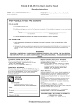
Cautions and Warnings
READ AND SAVE THESE INSTRUCTIONS. Follow the instructions in this installation manual. These instructions must be
followed to avoid damage to this product and associated equipment. Product operation and reliability depends upon proper
installation.
DO NOT INSTALL ANY PRODUCT THAT APPEARS DAMAGED. Upon unpacking your product, inspect the contents of
the carton for shipping damage. If damage is apparent, immediately file a claim with the carrier and notify Simplex.
ELECTRICAL HAZARD - Disconnect electrical field power when making any internal adjustments or repairs. Servicing
should be performed by qualified Technical Representatives.
STATIC HAZARD - Static electricity can damage components. Therefore, handle as follows:
• Ground yourself before opening or installing components.
• Prior to installation, keep components wrapped in anti-static material at all times.
RADIO FREQUENCY ENERGY - This equipment generates, uses, and can radiate radio frequency energy and if not installed
and used in accordance with the instruction manual, can cause interference to radio communications. It has been tested and
found to comply with the limits for a Class A computing device pursuant to Subpart J of Part 15 of FCC Rules, which are
designed to provide reasonable protection against such interference when operated in a commercial environment. Operation of
this equipment in a residential area may cause interference in which case the user at his own expense will be required to take
whatever measures may be required to correct the interference.
SYSTEM REACCEPTANCE TEST AFTER SOFTWARE CHANGES - To ensure proper system operation, this product must
be tested in accordance with NFPA72 after any programming operation or change in site-specific software. Reacceptance test-
ing is required after any change, addition or deletion of system components, or after any modification, repair or adjustment to
system hardware or wiring.
All components, circuits, system operations, or software functions known to be affected by a change must be 100% tested. In
addition, to ensure that other operations are not inadvertently affected, at least 10% of initiating devices that are not directly
affected by the change, up to a maximum of 50 devices, must also be tested and proper system operation verified.
Technical Manuals Online! - http://www.tech-man.com

Technical Manuals Online! - http://www.tech-man.com

Table of Contents
Overview ................................................................................................. 1-1
Main System Board.......................................................................................................................... 1-1
Power supply ................................................................................................................................... 1-2
Environmental Specifications .................................................................................................................. 1-2
Option Modules ....................................................................................................................................... 1-2
4006-9801 Expansion Power Supply (EPS) .................................................................................... 1-2
4006-9802 Expansion IDC Module (XIM) ....................................................................................... 1-2
4006-9805 and 4006-9806 City Circuit Cards.................................................................................. 1-2
4006-9803 Expansion Relay Module ............................................................................................... 1-2
Annunciator Modules ....................................................................................................................... 1-2
4009-9201/4009-9202CA NAC Extender ................................................................................................ 1-2
Initiating Devices ..................................................................................................................................... 1-3
Photoelectric Smoke Detector ......................................................................................................... 1-3
Heat Detector ................................................................................................................................... 1-3
Combination Photo/Heat Detector ................................................................................................... 1-3
Detector Bases ................................................................................................................................ 1-3
User Interface .......................................................................................................................................... 1-3
Logging In and Out .................................................................................................................................. 1-5
Login/Logout Procedure................................................................................................................... 1-5
Overview - Programming a Job ............................................................................................................... 1-5
Alarm Groups ................................................................................................................................... 1-6
Installation and System
Checkout................................................................................................. 2-1
Back Box Mounting.................................................................................................................................. 2-1
Removing Electronics Assembly...................................................................................................... 2-1
Conduit Entrances ........................................................................................................................... 2-1
Guidelines for Locating Backbox ..................................................................................................... 2-2
Surface Mounting ............................................................................................................................. 2-2
Semi-Flush Mounting ....................................................................................................................... 2-2
General Wiring Guidelines....................................................................................................................... 2-2
IDC Wiring ............................................................................................................................................... 2-3
Wiring 4098-9682 Four-Wire Base .................................................................................................. 2-4
NAC Wiring.............................................................................................................................................. 2-5
Technical Manuals Online! - http://www.tech-man.com

General Wiring Notes ....................................................................................................................... 2-5
Location of Expansion Power Supply NACs (If Used) ...................................................................... 2-5
NAC ratings ...................................................................................................................................... 2-7
Auxiliary Relay Wiring ..............................................................................................................................2-8
DACT........................................................................................................................................................2-9
Remote Annunciator Wiring ...................................................................................................................2-11
City Connect Module Wiring...................................................................................................................2-12
Auxiliary 24 V Wiring ..............................................................................................................................2-13
Connecting to AC Power ........................................................................................................................2-14
Wiring Battery Power..............................................................................................................................2-15
Depleted Battery Cutout .........................................................................................................................2-16
Safety Ground/Ferrite Bead ...................................................................................................................2-16
System Powerup and Checkout .............................................................................................................2-16
Acceptance Testing ........................................................................................................................ 2-16
Testing Circuit Supervision ............................................................................................................. 2-16
Replacing Lithium Battery ......................................................................................................................2-17
Periodic Testing and Maintenance .........................................................................................................2-17
Smoke Detector Tests .................................................................................................................... 2-17
Battery Tests................................................................................................................................... 2-17
Programming IDCs, NACs, and AUX Relays ....................................... 3-1
Default General Alarm Programming .......................................................................................................3-2
Accessing Menus .....................................................................................................................................3-2
Editing IDCs .............................................................................................................................................3-2
Setting IDC Function Type................................................................................................................ 3-2
Entering Labels................................................................................................................................. 3-4
Editing Alarm Groups........................................................................................................................ 3-5
Programming NACs .................................................................................................................................3-5
Setting NAC Function Type .............................................................................................................. 3-5
Editing Point Label............................................................................................................................ 3-7
Editing Alarm Groups........................................................................................................................ 3-7
Programming AUX Relays .......................................................................................................................3-8
Editing Point Label............................................................................................................................ 3-9
Clear Point Label .............................................................................................................................. 3-9
Saving Changes .......................................................................................................................................3-9
Programming the DACT ........................................................................ 4-1
Accessing DACT Menu ............................................................................................................................4-1
Programming DACT Options....................................................................................................................4-2
Enabling/Disabling DACT ................................................................................................................. 4-2
Setting Primary Phone Number ........................................................................................................ 4-2
Setting Primary Account Number...................................................................................................... 4-3
Setting Secondary Phone Number ................................................................................................... 4-3
Setting Secondary Account Number................................................................................................. 4-3
Setting Dialing Mode......................................................................................................................... 4-3
Technical Manuals Online! - http://www.tech-man.com

Setting Pulse Rate ............................................................................................................................ 4-3
Setting Pulse Frequency................................................................................................................... 4-4
Reporting Format.............................................................................................................................. 4-4
AC Fail Delay .................................................................................................................................... 4-4
Test Report Time .............................................................................................................................. 4-5
Programming Contact ID (CID) Points .....................................................................................................4-5
Programming Event Codes ......................................................................................................................4-6
Saving Changes .......................................................................................................................................4-6
Programming Annunciator LEDs ......................................................... 5-1
Adding an Annunciator .............................................................................................................................5-2
Automatically Adding Annunciator Cards.......................................................................................... 5-2
Manually Adding an Annunciator Module ......................................................................................... 5-2
Accessing Annunciator Menus .................................................................................................................5-2
Programming LEDs Located on Zone Annunciator and Remote LED/Switch Modules ...........................5-3
Mapping LEDs to Software Points .................................................................................................... 5-3
Programming Overview .................................................................................................................... 5-3
Default Programming........................................................................................................................ 5-3
Programming the LED’s Mode and Reference Point ........................................................................ 5-4
Programming Panel LEDs........................................................................................................................5-6
Setting LED Color ............................................................................................................................. 5-6
Setting LED Mode and Reference Point........................................................................................... 5-6
Common LED Applications ......................................................................................................................5-7
Saving Changes .......................................................................................................................................5-7
Programming System Options ............................................................. 6-1
Accessing System Options Menu.............................................................................................................6-1
Programming Options ..............................................................................................................................6-1
Saving Changes .......................................................................................................................................6-4
Operating ................................................................................................ 7-1
Normal Operation .....................................................................................................................................7-1
Lamp Test ................................................................................................................................................7-1
Abnormal Conditions ................................................................................................................................7-1
Silencing Alarms.......................................................................................................................................7-2
System Reset ...........................................................................................................................................7-2
Viewing/Clearing Historical Logs..............................................................................................................7-2
Viewing Logs .................................................................................................................................... 7-2
Clearing Logs.................................................................................................................................... 7-3
Viewing and Controlling Points.................................................................................................................7-3
Viewing Point Information ................................................................................................................. 7-3
Manually Activating a NAC/Relay.............................................................................................................7-4
Enabling or Disabling Points ....................................................................................................................7-4
Technical Manuals Online! - http://www.tech-man.com

Control Functions .....................................................................................................................................7-4
Setting the Time and Date........................................................................................................................7-5
Reports.....................................................................................................................................................7-5
Diagnostics...............................................................................................................................................7-5
WalkTest ..................................................................................................................................................7-6
Setting WalkTest Options ................................................................................................................. 7-6
Advanced Operations...............................................................................................................................7-7
Upload/Download ............................................................................................................................. 7-7
Restarting the CPU........................................................................................................................... 7-7
Viewing Software Revision Number and Job Info............................................................................. 7-7
Appendix A. Battery Standby Calculations
Current Draw for System Components ................................................................................................... A-1
Appendix B. Contact ID Default Values
Technical Manuals Online! - http://www.tech-man.com

Technical Manuals Online! - http://www.tech-man.com

Technical Manuals Online! - http://www.tech-man.com

1-1
This publication describes how to install, configure, operate, program,
and test an 4006-9101 and 4006-9121 (includes door-mounted annunci-
ator) Fire Alarm Control Panel (FACP). In cases where the installation,
wiring, or programming procedure is identical for both panels, the term
4006 is used. If the procedure applies only to a specific panel, the com-
plete product name (i.e., 4006-9121 is used).
The 4006 is a conventional fire alarm control panel. The base system
includes five Class B Initiating Device Circuits (IDCs), which may be
wired as Class A circuits with the addition of an optional Class A mod-
ule. The base system also includes two Notification Appliance Circuits
(NACs), which may be wired class A or class B. A built-in DACT pro-
vides a means for remote station or central station monitoring.
The 4006 provides audible and visible indications during alarm, super-
visory, or trouble conditions. Should any of these conditions occur, the
system activates the applicable notification appliances, LEDs, and the
panel tone-alert. The indications continue until an operator acknowl-
edges the condition.
Main System Board
The 4006 base system includes the Main System Board (MSB) mounted
in a steel enclosure with locking door.
The MSB contains everything needed for a UL-listed fire alarm system
on one board. It consists of:
• System power supply (3A); 24V filtered
• Five IDCs (Class B)
• Two, 2A Notification Appliance Circuits (Class A or B)
• DACT
• Two auxiliary relay circuits
• One auxiliary power tap
• 2x20 backlit LCD, LEDs and keypad
• Service Port
• Expansion power supply connection
• Expansion IDC connection
• Expansion port for Class A IDC adapter connection
• Connection for interface to optional city card
• Communication channel for remote annunciators
• Battery-backed, non-volatile memory preserves logs, time/date
information, and disabled points on AC loss.
In This Chapter
Environmental Specifications . . . . . . . . . . . . . .1-2
Option Modules . . . . . . . . . . . . . . . . . . . . . . . .1-2
4009-9201/4009-9202CA NAC Extender. . . . .1-2
Initiating Devices . . . . . . . . . . . . . . . . . . . . . . .1-3
User Interface. . . . . . . . . . . . . . . . . . . . . . . . . .1-3
Logging In and Out. . . . . . . . . . . . . . . . . . . . . .1-5
Overview - Programming a Job . . . . . . . . . . . .1-5
Chapter 1. Overview
Technical Manuals Online! - http://www.tech-man.com

Chapter 1. Overview
1-2
Power supply
• 120 VAC, 60 Hz, 4A; 240V, 50 Hz, 3A
• 24 VDC (filtered) 3A alarm power
• 24 VDC, ½A auxiliary power
• Battery charger up to 25 Ah batteries per UL864; tem-
perature compensated. Recharge 12.7Ah batteries per
ULC-S527.
Note: The 4006 back box can accommodate up to
12.7 Ah batteries.
Environmental Specifications
The panel operates normally with ambient temperatures
from 32° F to 120° F (0° C to 49° C), inclusive.
The panel operates normally under non-condensing humid-
ity conditions up to 93% relative humidity at 90° F (32° C).
Option Modules
The following lists all of the option modules for the 4006.
Refer to the individual instructions that accompany each
module for more information. Refer to the label inside the
door of the 4006 for the placement of optional modules.
4006-9801 Expansion Power Supply (EPS)
When additional notification appliance circuits are required,
an expansion power supply may be added. The expansion
power supply provides two additional 2A NACs, and fil-
tered/regulated 24 VDC, 3A power. The expansion power
supply is mounted to the right of the MSB at the bottom of
the chassis. It connects to the MSB with a ribbon harness.
The 3A alarm power of the EPS may be split between the 2
NACs and the 1/2A Aux. 24V power tap. One EPS per sys-
tem is allowed.
4006-9802 Expansion IDC Module (XIM)
This module mounts to the right of the MSB. It includes five
Class B Initiating Device Circuits, and a mounting point for
the optional IDC Class A adapter module.
4006-9805 and 4006-9806 City Circuit Cards
The city circuit card connects to the MSB with a ribbon har-
ness to provide connections to either Remote Station
(reverse polarity), or Municipal Master (local energy)
receiving units (selectable). The card has two circuits - cir-
cuit 1 reports alarm or alarm/trouble events (Remote Station
only) and circuit 2 can be configured to report trouble events
or supervisory events. In the event of a CPU failure, a city
card configured for a trouble output sends a trouble to the
city circuit. The card is mounted to the right of the MSB at
the top of the chassis. The 4006-9805 and 4006-9806 city
cards are identical except that the 4006-9805 provides hard-
ware disconnect switches for each circuit. One City Circuit
Card per system is allowed.
4006-9803 Expansion Relay Module
The Expansion Relay Module (ERM) includes 10 relays.
The relays may be programmed for per-zone operation, one
relay per IDC, or as desired. For example, it is possible to
program any relay for general alarm, trouble or supervisory
conditions. Normally Open or Normally Closed contact
operation is selected by shunt jumper placement. Contacts
are rated for 2A, 30VDC, 0.35 power factor.
Annunciator Modules
The 4006 supports the following annunciator modules. A
total of four annunciators may be added to the system, one of
which can be located in the panel (the Local Zone LED
module).
• Local Zone LED Module. The local Zone LED
Modules provides 24 LEDs for visible zone alarm and
trouble indication. (The Local Zone LED module,
which mounts on the front of the panel, is standard for
ULC-S527 compliant systems.) There are 10 Red and
14 Yellow LEDs. This provides a red alarm and yellow
trouble LED for each of 10 initiating device circuits.
This module also provides 4 Yellow LEDs, one for each
of 4 NACs. The LEDs are programmable, and can be
used for other functions as appropriate per application.
• 4610-9111 Remote LED/Switch Annunciator.
This annunciator provides the following:
- 10 programmable red LEDs (default programming
tracks alarm state of IDC1-IDC10)
- 6 programmable yellow LEDs (no default opera-
tion)
- Green “power on” LED
- Yellow “Alarm Silenced” LED
- Yellow “Trouble”
- Yellow “Comm Loss” LED
- Tone-Alert
- Switches for ACK, Alarm Silence, System Reset,
and Lamp Test
- Key switch to enable switch functions
4009-9201/4009-9202CA NAC
Extender
The 4009-9201/4009-9202CA (Canadian) Notification
Appliance Circuit (NAC) Extenders are self-contained
Technical Manuals Online! - http://www.tech-man.com

Chapter 1. Overview
1-3
adjunct panels for use with 4006 Fire Alarm Control Panels
(FACPs).
The base version of the NAC Extender is a single-board sys-
tem consisting of four NACs, a power supply and charger,
and two conventional NAC inputs that connect to the host
panel for hardwired control of the NAC extender.
Option cards are available to provide the following addi-
tional capabilities:
• 4009-9808 Class A Adapter Option Card -- allows fault
tolerance in the case of open circuit wiring faults on the
NACs.
• 4009-9807 NAC Option Card -- adds four conventional
Notification Appliance Circuits.
Initiating Devices
The 4006 is compatible with the following conventional ini-
tiating devices.
Photoelectric Smoke Detector
Photoelectric smoke detectors detect smoke by means of
optical sensing technology.
• 4098-9601/4098-9601C: Standard Sensitivity (2.8%/
foot) Photoelectric Smoke Detector
• 4098-9605: Special Sensitivity (3.5%/foot) Photoelec-
tric Smoke Detector
Heat Detector
Four models of conventional electronic heat detector are
available:
• 4098-9612/4098-9612C: 135°F Fixed Temperature
Heat Detector
• 4098-9613/4098-9613C: 135°F Fixed Temperature
Heat Detector w/ rate of rise detection
• 4098-9614/4098-9614C: 200°F Fixed Temperature
Heat Detector
• 4098-9615/4098-9615C : 200°F Fixed Temperature
Heat Detector w/ rate of rise detection
The rate of rise trigger is 15°F-25°F per minute.
Combination Photo/Heat Detector
The combination photo/heat detector ( 4098-9602/4098-
9602C) is a combination photoelectric detector and thermal
detector in one head. This detector correlates smoke and
thermal activity to provide earliest alarm initiation.
• Smoke detector sensitivity: 2.8% /ft. obscuration
• Fixed temperature trip point: 135°F
Rate of Rise trigger: 15°F-25°F per minute only at tempera-
tures of 90°F or greater
Detector Bases
The detectors described above may be installed in the fol-
lowing detector bases:
• 4098-9788/4098-9788C: Two-wire detector base with
remote LED connection.
• 4098-9683/4098-9683C: Two wire detector base with
auxiliary relay (limit 1 per IDC).
• 4098-9684/4098-9684C: Two wire detector base with
alarm LED output. For use with 4098-961x series heat
detectors only.
• 4098-9682/4098-9682C: Four wire detector base with
auxiliary alarm relay .
Each of the smoke detectors includes an output for a remote
alarm LED. Base 4098-9684 is required for remote LED
control with 4098-9612 through 4098-9615 electronic heat
detectors.
Maximum of 30 total bases per IDC, except for 4098-9683
(limit one per IDC).
User Interface
The user interface consists of control keys, LEDs, a 2-line
by 20-character backlit LCD, and a sounder mounted in the
control panel. The purpose of the Operator and Menu keys is
listed below.
Figure 1-1 User Interface
Technical Manuals Online! - http://www.tech-man.com

Chapter 1. Overview
1-4
Table 1-1 Operator Keys
Key Function
ALARM
ACK
Acknowledges any unacknowledged fire
alarms in the system, and scrolls
through the alarms in the active Alarm
List.
SUPV
ACK
Acknowledges any unacknowledged
supervisories in the system, and scrolls
through the supervisory conditions in the
active Supervisory List.
TROUBLE
ACK
Acknowledges any unacknowledged
troubles in the system, and scrolls
through the trouble conditions in the
active Trouble List.
ALARM
SILENCE
Silences any silenceable output types
(generally all audible notification appli-
ances).
SYSTEM
RESET
Allows the operator to reset all alarm
notification appliances and controls,
remove alarms from the Alarm List,
silence all silenceable outputs, reset
detectors, and return the system to a
normal state (provided that no alarm,
supervisory or trouble conditions are
present). The display indicates that a
reset is in progress and whether or not a
reset completes successfully.
Pressing the <SYSTEM RESET> key
will only attempt to return the system to
a normal, non-alarm state. All outputs
that were activated by the alarm will
remain active until all alarm inputs have
been restored and the reset was able to
successfully complete.
An open circuit fault on a Class A NAC
does not require a System Reset to
restore to normal.
Open circuit faults on the optional City
Connect module are cleared with a sys-
tem reset after the circuit has been
repaired.
MENU
The Menu key always brings you to the
top of the main menu structure unless
you are in the Programming menu.
FUNCTION
The Function Menu is displayed when
the <Function> key is pressed at the
high-level status screen. Use the <Previ-
ous> and <Next> keys to scroll through
the list of functions. The function key
provides access to commonly used con-
trol and display functions.
DISABLE/
ENABLE
The <Disable/Enable> key allows the
operator to quickly disable or enable any
point that is currently displayed. This key
is passcode protected. A confirmation
screen is displayed requesting <Enter>
be pressed before the actual enable or
disable is performed.
EXIT/
CLEAR
The <Exit/Clear> key is used to back out
of menus or displays and return to the
top-level menu structure. Where possi-
ble, the <Exit/Clear> key backs out one
level at a time. There are cases, how-
ever, that the Exit/Clear key will return
the operator directly to the top-level
menu.
ENTER
The <Enter> key is used to confirm
selections. When pressed, this key pro-
vides additional information about the
point shown on the display. In a pro-
gramming screen, pressing <Enter>
indicates that the information on the dis-
play is correct and can be accepted. The
<Enter> key is used in various other
places within the menu structure, always
for this same type of operation.
RIGHT/LEFT
ARROWS
The right and left arrows are used in
screens with multiple choices. The keys
advance the focus (square brackets [ ])
from field to field.
PREVIOUS/
NEXT
The Previous & Next keys are used to
scroll through the system lists, historical
log, point database, etc. The <Next> key
selects the next display screen in
sequence, and the <Previous> key
selects the previous screen. These keys
are also used to view additional informa-
tion about abnormal points or in viewing
historical logs.
Table 1-1 Operator Keys (Continued)
Key Function
Technical Manuals Online! - http://www.tech-man.com

Chapter 1. Overview
1-5
Logging In and Out
Certain operator functions are passcode-protected at differ-
ent levels. This section describes the operator functions,
their default access level, and the login/logout procedure.
Login/Logout Procedure
To perform any of the functions protected at Level 2 or
above, you must login to the panel using a passcode. After
completing a task at a certain access level, you should then
logout to return the access level to Level 1 to prevent unau-
thorized operation. When logged in at Level 2 or above and
no panel keys are pressed for more than 10 minutes, the
panel automatically returns the system to Level 1.
All passcodes consist of a 4-digit number. Logging in at
Level 4 causes a Service Mode trouble that may only be
cleared by restarting the panel.
To login, perform the following steps:
1. Obtain the passcode information for the desired level.
2. Press <MENU>
3. Press <NEXT> until [Login/Logout] is displayed, then
press <ENTER>. A prompt similar to the following
appears.
Access: Level 1
<ENTER>=[Login]
4. Press <NEXT> until [Login] is displayed, then press
<ENTER>. A prompt similar to the following appears.
Access: Level 1
Passcode: [0]
5. Use the Keypad to enter the appropriate passcode.
6. When the passcode is correct, press the <ENTER> key
to login.
A “Login Accepted” message, which indicates your current
access level, is displayed briefly upon a successful login
attempt. If you did not enter the appropriate Login passcode,
a “Login Invalid” screen appears.
To logout, perform steps 1-4 above, but select Logout
instead of Login.
Overview - Programming a Job
A job refers to the file containing all of the panel’s program-
ming information. This manual describes the process
required to create a job from the front panel of the system.
Creating a job involves:
• Setting the attributes of each IDC, NAC, and AUX
relay, including:
- Function Type. Determines the way in which the
IDC, NAC, or relay operates (i.e., fire point, trouble
point, on til silence, etc.)
- Custom Label. This is a 20-character label that
describes each zone, NAC, or relay.
- Alarm Group. Allows inputs and outputs to be
associated into groups to implement selective sig-
naling applications. See “Alarm Groups” below.
• Defining the attributes (phone numbers, account num-
bers, reporting format, etc.) of the panel’s Digital Alarm
Communicator Transmitter (DACT). If the DACT will
not be used, programming consists of disabling the
DACT.
• Programming the operation of the LEDs contained on
the panel and connected annunciators. Programming an
annunciator consists of identifying the point being mon-
itored by the LED and the mode (i.e., fire alarm, trou-
ble, etc.) that will trigger the LED to illuminate.
• Setting values for the panel’s system options, which are
pre-defined modes of operation with a range of settings
from which to choose. System Options define global
operations such as the time and date format, door drop
timers, and whether the city circuit is enabled, etc.
Table 1-2 Access Levels and Features
Access
Level
Operation
1
Acknowledge, Silence, System Reset,
View Historical Logs,
View Point Information, Lamp Test
2
Passcode =
2000
All Level 1 operations, plus:
Set Time/Date, Point Control,
Enable/Disable points
3
Passcode =
3000
All Level 1 & 2 operations, plus:
Clear Historical Logs,
Clear Verification Tallies
Custom Label editing
WALKTEST
4
Passcode =
4000
All Level 1, 2, & 3 operations, plus:
Programming,
Upload/Download
Technical Manuals Online! - http://www.tech-man.com

Chapter 1. Overview
1-6
Alarm Groups
Alarm groups allow you to implement basic selective signal-
ling applications. As you program input (zone of smoke
detectors) and output points (NAC or relay), you are given
the opportunity to associate the point with an alarm group
number. The number can range from 1-100 and each point
can be in up to three alarm groups. When programming is
complete, an initiating device can only trigger the output
devices (relays, NACs) that share its alarm group(s).
Technical Manuals Online! - http://www.tech-man.com

2-1
Back Box Mounting
The back box can be surface-mounted or semi-flush mounted to the
wall. Use separate conduit entrances for power-limited and non-power
limited wiring.
AC supply, battery supply, and City Connect wiring are all non-power
limited wiring.
Removing Electronics Assembly
Use either a #6 Torx or a slot-head screwdriver to remove the four
screws that secure the electronics assembly to the back box.
Conduit Entrances
• Nine knockouts are provided for conduit connection. Refer to Fig-
ure 2-1 for knockout locations.
• Power limited wiring must be located only in the shaded area of
the cabinet.
• AC power (non-power limited) wiring must be run in separate con-
duit from all other wiring, as shown in the figure below. Non-
power limited wiring must be separated from power limited
wiring by a minimum of 1/4”.
Figure 2-1 Power-Limited (Shaded) and
Non-Power Limited Wiring Areas
TB1 TB2 TB3
Battery
AC Voltage
Connection
Battery
Connection
Battery
City Connect
Module
Expansion
Power Supply
DACT
In This Chapter
Back Box Mounting . . . . . . . . . . . . . . . . . . . . 2-1
General Wiring Guidelines . . . . . . . . . . . . . . . 2-2
IDC Wiring . . . . . . . . . . . . . . . . . . . . . . . . . . . 2-3
NAC Wiring . . . . . . . . . . . . . . . . . . . . . . . . . . 2-5
Auxiliary Relay Wiring . . . . . . . . . . . . . . . . . . 2-8
DACT . . . . . . . . . . . . . . . . . . . . . . . . . . . . . . . 2-9
Remote Annunciator Wiring . . . . . . . . . . . . . 2-11
City Connect Module Wiring. . . . . . . . . . . . . 2-12
Auxiliary 24 V Wiring . . . . . . . . . . . . . . . . . . 2-13
Connecting to AC Power . . . . . . . . . . . . . . . 2-14
Wiring Battery Power . . . . . . . . . . . . . . . . . . 2-15
Depleted Battery Cutout. . . . . . . . . . . . . . . . 2-16
Safety Ground/Ferrite Bead . . . . . . . . . . . . . 2-16
System Powerup and Checkout. . . . . . . . . . 2-16
Replacing Lithium Battery . . . . . . . . . . . . . . 2-17
Periodic Testing and Maintenance . . . . . . . . 2-17
Chapter 2. Installation and System
Checkout
Technical Manuals Online! - http://www.tech-man.com

Chapter 2. Installation and System Checkout
2-2
• All Aux Relay loads must be powered from the AUX
power circuit or from a regulated, 24 VDC, power-lim-
ited power supply that is UL-listed for fire protective
signaling service.
Guidelines for Locating Backbox
Always refer to engineering drawings/site installation plans
before beginning installation. The system is designed to
operate in a typical commercial environment. Choose a site
for each backbox that is:
• Well-ventilated, clean, and dust-free.
• Located near a dedicated AC individual branch circuit
with Earth ground (to maintain a consistent supply volt-
age).
• Away from sources of heat, including direct sunlight.
• Away from sources of vibration or physical shock.
• Away from sources of Radio Frequency Interference
(RFI), such as a radio transceiver base station or hand
held unit.
• Isolated from sources of strong electromagnetic fields,
such as air conditioners, large fans, and large electric
motors.
Be sure to mount the backbox to the wall so that the top of
the enclosure is no more than six feet above the floor.
Surface Mounting
Refer to the figure below for hole dimensions.
Figure 2-2 Surface Mounting Hole Dimensions
Semi-Flush Mounting
Semi-flush mounting involves recessing the backbox into a
wall and attaching it directly to the wall's studs. At a mini-
mum, 1.5 inches of the backbox must protrude from the wall
to allow for clearance of the panel door.
Figure 2-3 Semi-Flush Mounting
General Wiring Guidelines
All wiring to the 4006 and its peripherals must be performed
in accordance with NFPA 70, NFPA 72, all local codes, and
per the technical requirements listed in each section below.
Before connecting any wires to the system, including option
modules, wires must be tested as follows:
1. Use a voltmeter (VOM) to verify no stray voltages are
applied to the field wiring. Test for AC and DC voltages
across each pair of wires and from each wire to earth.
2. Use a VOM to verify that all wiring tests free of
grounds. Each conductor should test “open” against
earth (chassis).
1.5”
Technical Manuals Online! - http://www.tech-man.com
/