Page is loading ...

FIRE
4098 Detectors, Sensors, and Bases
Application Manual
574-709
Rev. T
firealarmresources.com

ii
firealarmresources.com

iii
© 2008- 2011 SimplexGrinnell LP. All rights reserved.
Specifications and other information shown were current as of publication and are subject to
change without notice.
Suffix “C” or “CA” following an eight-digit Product ID number denotes ULC-listed product.
Suffix “E” following an eight-digit Product ID number denotes Global product. The second suffix
identifies market country, models with this suffix are not UL Listed.
Tyco, IDNet
, Simplex and the Simplex logo are trademarks of Tyco International Ltd. and its
affiliates and are used under license.
MAPNET II
Communication Net is protected by US Patent No. 4,796,025.
TrueAlarm
Analog Detection is protected by US Patent No. 5,155,468.
TrueAlarm
Detector Base is protected by US Patent No. 5,173, 683.
All illustrations of actual detectors, sensors, and bases shown in this publication are artist’s renditions.
Copyrights and Trademarks
Copyrights
Trademarks
firealarmresources.com

iv
Cautions and
Warnings
READ AND SAVE THESE INSTRUCTIONS- Follow the instructions in this installation
manual. These instructions must be followed to avoid damage to this product and associated
equipment. Product operation and reliability depend upon proper installation.
DO NOT INSTALL ANY SIMPLEX® PRODUCT THAT APPEARS DAMAGED- Upon
unpacking your Simplex product, inspect the contents of the carton for shipping damage. If
damage is apparent, immediately file a claim with the carrier and notify an authorized
Simplex product supplier.
ELECTRICAL HAZARD - Disconnect electrical field power when making any internal adjust-
ments or repairs. All repairs should be performed by a representative or authorized agent of
your local Simplex product supplier.
STATIC HAZARD - Static electricity can damage components. Handle as follows:
Ground yourself before opening or installing components.
Prior to installation, keep components wrapped in anti-static material at all times.
FCC RULES AND REGULATIONS – PART 15 - This equipment has been tested and
found to comply with the limits for a Class A digital device pursuant to Part 15 of the FCC
Rules. These limits are designed to provide reasonable protection against harmful
interference when the equipment is operated in a commercial environment. This equipment
generates, uses, and can radiate radio frequency energy and, if not installed and used in
accordance with the instruction manual, may cause harmful interference to radio
communications. Operation of this equipment in a residential area is likely to cause harmful
interference in which case the user will be required to correct the interference at his own
expense.
Cautions and Warnings
firealarmresources.com

v
Copyrights and Trademarks ........................................................................................... iii
Copyrights ................................................................................................................... iii
Trademarks ................................................................................................................. iii
Cautions and Warnings .................................................................................................. iv
Table of Contents ............................................................................................................ v
Chapter 1 Overview .............................................................................. 1-1
Introduction .............................................................................................................. 1-1
In this Chapter ......................................................................................................... 1-1
Special Considerations ................................................................................................ 1-2
Overview .................................................................................................................. 1-2
Special Considerations for Smoke Detectors and Sensors ..................................... 1-2
Smoke Detector/Sensor Applications ...................................................................... 1-2
Where to Place Detectors and Sensors ...................................................................... 1-3
Proper Locations for Detectors and Sensors ........................................................ 1-3
Where Not to Place Detectors and Sensors ................................................................ 1-6
Improper Locations for Detectors and Sensors ....................................................... 1-6
Principles of Operation ................................................................................................ 1-8
Introduction .............................................................................................................. 1-8
Heat Detector Operation .......................................................................................... 1-8
Photoelectric Smoke Detectors/Sensors ................................................................. 1-8
Ionization Smoke Detectors/Sensors ...................................................................... 1-8
Carbon Monoxide Gas Detectors/Sensors .............................................................. 1-8
Chapter 2 4098 Smoke Detectors, Heat Detectors and Bases .......... 2-1
Introduction .............................................................................................................. 2-1
In this Chapter ......................................................................................................... 2-1
4098 Smoke Detectors ................................................................................................ 2-2
Introduction .............................................................................................................. 2-2
Smoke Detector Limitations ..................................................................................... 2-2
Specifications ........................................................................................................... 2-3
Mounting Requirements ........................................................................................... 2-4
4098 Heat Detectors .................................................................................................... 2-5
Introduction .............................................................................................................. 2-5
Heat Detector Types ................................................................................................ 2-5
Specifications ........................................................................................................... 2-5
4098 Bases .................................................................................................................. 2-8
Introduction .............................................................................................................. 2-8
Mounting .................................................................................................................. 2-9
Wiring ..................................................................................................................... 2-10
Chapter 3 TrueAlarm Sensors, Sensor Bases, and QuickConnect
Smoke Sensors .................................................................................... 3-1
Introduction .............................................................................................................. 3-1
Table of Contents
firealarmresources.com

vi
In this Chapter ......................................................................................................... 3-1
4098 TrueAlarm Sensors ............................................................................................. 3-2
Specifications ........................................................................................................... 3-2
Special Applications ................................................................................................. 3-2
Mounting .................................................................................................................. 3-2
4098 TrueAlarm Sensor Bases ................................................................................... 3-3
Introduction .............................................................................................................. 3-3
Specifications ........................................................................................................... 3-3
Setting the Base’s Address...................................................................................... 3-3
Address Setting for the 2120 CDT System.............................................................. 3-5
Address Setting for the 4010, 4020, 4100+, 4100U, 4100ES, 4008, or 4120 System3-5
Multi-Sensor Bases 4098-9795 and 4098-9796 ..................................................... 3-7
Wiring ....................................................................................................................... 3-7
4098 TrueAlarm QuickConnect Smoke Sensors ....................................................... 3-12
Overview ................................................................................................................ 3-12
Specifications ......................................................................................................... 3-12
Setting the Sensor’s Address ............................................................................... 3-13
Wiring ..................................................................................................................... 3-14
Chapter 4 Accessories ......................................................................... 4-1
Introduction .............................................................................................................. 4-1
In this Chapter ......................................................................................................... 4-1
Relay Module Accessories .......................................................................................... 4-2
2098-9737 Relay Module Wiring ............................................................................ 4-2
4098-9822 Relay Module Wiring ............................................................................. 4-3
Relay Module Installation......................................................................................... 4-4
Remote LED Module ............................................................................................... 4-4
Chapter 5 Compatibility and Testing .................................................. 5-1
Introduction .............................................................................................................. 5-1
In this Chapter ......................................................................................................... 5-1
Compatibility ................................................................................................................ 5-2
Compatibility for 4098 Detectors and Detector Bases ............................................. 5-2
Maintenance and Testing ............................................................................................ 5-4
Maintenance ............................................................................................................ 5-4
Preferred Method of Testing Smoke Detectors/Sensors ......................................... 5-4
Test Equipment Available ........................................................................................ 5-4
Alternate Method for Testing Sensors ..................................................................... 5-5
Magnetic Test for Photoelectric Detectors ............................................................... 5-5
Magnetic Test for Ionization Detectors .................................................................... 5-7
Ion Detector Sensitivity Test .................................................................................... 5-7
Cleaning ....................................................................................................................... 5-8
Introduction .............................................................................................................. 5-8
Photoelectric Smoke Detector/Sensor Cleaning ..................................................... 5-8
Special Considerations for Ion Detectors and Sensors ........................................... 5-8
Trouble Indications ...................................................................................................... 5-9
Trouble Indications for TrueAlarm Sensors ............................................................. 5-9
Trouble Indications, Continued .................................................................................. 5-10
firealarmresources.com

vii
Fire Alarm Trouble and Maintenance Log ................................................................. 5-11
Fire Alarm Trouble and Maintenance Log ............................................................ 5-11
Index ............................................................................................................................. I-1
firealarmresources.com

firealarmresources.com

1-1
The purpose of this publication is to provide information concerning the proper application of both
heat and smoke detectors/sensors in conjunction with fire alarm systems.
The information in this publication is intended to be used only as a technical guide. The
requirements of applicable codes and standards, as well as directives of Authorities Having
Jurisdiction (AHJ’s), should be followed.
Refer to the page number listed in this table for information on a specific topic.
Topic See Page #
Special Considerations 1-2
Where to Place Detectors and Sensors 1-3
Where Not to Place Detectors and Sensors 1-6
Principles of Operation 1-8
Chapter 1
Overview
Introduction
In this Chapter
firealarmresources.com

1-2
Before installing detectors/sensors, make a survey of the area to be covered in accordance with
information provided in NFPA 72, (an excerpt of which is provided in the “Smoke Detector/
Sensor Applications” section below). For additional information, refer to NFPA 72 and the
NEMA Guide for Proper Use of System Smoke Detectors.
Is there human occupancy?
Contents to be protected.
Type of construction and use.
Burning characteristics of contents.
Air movement - stratification.
Deflections and obstructions.
Height of ceilings.
Surface conditions of ceilings.
Type of ceiling construction.
Total area.
Vent locations - velocities - dilution.
Each detector/sensor is capable of providing up to 900 square feet (84 square meters) of coverage,
depending on the following:
Requirements of local codes.
Results of engineering evaluation.
Special Considerations
Overview
Special
Considerations for
Smoke Detectors
and Sensors
Smoke
Detector/Sensor
Applications
firealarmresources.com

1-3
IMPORTANT: The guidelines in this section are adapted from standards
published by the National Fire Protection Association, Quincy,
Massachusetts, U. S. A. These standards include NFPA 72,
“National Fire Alarm Code”; NFPA 70, “National Electrical Code”,
Article 760; and NFPA 90A, “Standard for the Installation of
Air Conditioning and Ventilating Systems.”
To provide effective early warning of a developing fire situation, smoke detectors/sensors should
be installed in all areas of the protected premises. Total coverage as defined by NFPA 72 should
include all rooms, halls, storage areas, basements, attics, lofts, and spaces above suspended
ceilings including plenum areas utilized as part of the HVAC system. In addition, this should
include all closets, elevator shafts, enclosed stairways, dumbwaiter shafts, chutes and other
subdivisions and accessible spaces.
Fire detection systems installed to meet local codes or ordinances may not be adequate for early
warning of the fire. Some codes or ordinances have minimum objectives such as capturing
elevators or preventing circulation of smoke through HVAC systems instead of early detection of
fire.
You should weigh the costs against the benefits of installing a complete fire detection system
when any detection system is being installed. The location, quantity and zoning of
detectors/sensors should be determined by what objectives are desired rather than the minimum
requirements of any local codes or ordinances.
Detectors/sensors may be omitted from combustible blind spaces when any of the following
conditions prevail:
Where the ceiling is attached directly to the underside of the supporting beams of a
combustible roof or floor deck.
Where the concealed space is entirely filled with noncombustible insulation. (In solid joist
construction, the insulation need only fill the space from the ceiling to the bottom edge of the
joist of the roof or floor deck.)
Where there are small concealed spaces over rooms, provided the space in question does not
exceed 50 square feet (4.6 square meters).
In spaces formed by sets of facing studs or solid joists in walls, floors, or ceilings where the
distance between the facing studs or solid joists do not exceed 6 inches (15 cm).
Detectors/sensors may also be omitted from below open grid ceilings where all of the following
conditions are met:
The openings of the grid are at least 1/4 inch (6 mm) in the smallest dimension.
The thickness of the material does not exceed the smallest of the grid openings.
The openings constitute at least 70% of the area of the ceiling material.
Continued on next page
Where to Place Detectors and Sensors
Proper Locations
for Detectors
and Sensors
firealarmresources.com

1-4
Detectors/sensors are usually required or recommended underneath open loading docks or
platforms and their covers, and in accessible under-floor areas in buildings without basements.
Detectors/sensors may be omitted from combustible blind spaces when all of the following
conditions prevail:
1. The space is not accessible for storage purposes, it is protected against the entrance of
unauthorized persons, and it is protected against the accumulation of windblown debris.
2. The space contains no equipment/structures (such as steam pipes, electrical wiring, ducts,
shafts, or conveyors) that could potentially ignite or conduct the spread of fire.
3. The floor over the space is tight.
4. Non flammable liquids are processed, handled, or stored on the floor above the space.
“Total coverage” as described in NFPA 72, is the definition of a complete fire detection system.
In some of the specified areas of coverage, such as attics, closets, under open loading docks or
platforms, a heat detector may be more appropriate than a smoke detector. Careful consideration
should be given to the detector manufacturer’s instructions and the following recommendations in this
guide.
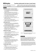
In general, when only one detector/sensor is required in a room or space, the detector/sensor should
be placed as close to the center of the ceiling as possible. Central location of the detector/sensor is
best for sensing smoke and/or fire in any part of the room. If a center location is not possible, it may
be placed no closer than 4 inches (10 cm) from the wall, or if listed for wall mounting, it may be
mounted on the wall. Wall mounted detectors/sensor should be located approximately 4 to 12 inches
(10 to 30 cm) from the ceiling to the top of the detector, and at least 4 inches (10 cm) from any
corner wall junction (see the figure below).
FigureTag FD4-709-01
4 in
(10 cm)
Minimum
12 in
(30 cm)
Maximum
Never here
Top of t he detect or
acceptabl e here
Side
wall
Acceptabl e here
Ceiling
Not e:
Measurements shaown are to the
cl osest edge of the detect or.
4 in
(10 cm)
Figure 1-1. Wall and Ceiling Mounted Detector/Sensor
Continued on next page
Where to Place Detectors and Sensors,
Continued
Proper Locations
for Detectors
and Sensors
Note: Measurements shown are to the
closest edge of the detector.
firealarmresources.com

1-5
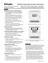
When an air supply and/or an air return duct opening is present in a room or space, the
detector/sensor(s) should be placed in the path of the air flow toward the return air duct opening
(see below).
FigureTag FD4-709-02
Retur
n
air Correct Suppl
y
air Incorrect
Figure 1-2. Detector Placement - Air Supply and/or Return Ducts
Smoke tests are helpful in determining proper placement. Special attention should be given
to smoke travel directions and velocity, since either can affect detector/sensor performance.
Placement of a detector/sensor near air conditioning or incoming air vents can also cause
excessive accumulation of dust and dirt on the detector/sensor. This dirt can cause the
detector/sensor to malfunction and cause nuisance alarms. Detectors/sensors should not be located
closer than 3 feet (0.9 m) from an air supply diffuser.
Spot type detectors/sensors in properly engineered systems, may also be placed in return air ducts, or
in approved duct detector housings designed for this application. Although duct detectors are not a
substitute for open area detectors, they can provide an effective method of initiating building control
functions to prevent smoke from being transported from the fire area to other parts of a building.
Where to Place Detectors and Sensors,
Continued
Proper Locations
for Detectors
and Sensors
firealarmresources.com

1-6
One of the major causes of nuisance alarms is improper placement of detectors/sensors.
The best way to avoid nuisance alarms is to not install detectors/sensors in environments that can
cause them to malfunction. See the table and examples provided below.
Table 1-1. Environmental Conditions that Influence Detector Response*
Detection
Protection
Air Velocity
>300 ft.
(91.4m)/min.
Atm. Pressure
3000 ft. (914m)
Above Sea Level
Humidity
>93% RH Temp. <32°F (0C)
>100°F (38C) Color of
Smoke
Ion X X X X O
Photo O O X X X
Beam O O X X O
Air Sampling O O X X O
* See Table A-5-3.6.1.1 in NFPA 72
X = May affect detector/sensor response
O = Generally does not affect detector/sensor response
DO NOT PLACE DETECTORS/SENSORS:
In excessively dusty or dirty areas, such as feed rooms, steel mills, etc. Dust and dirt can
accumulate on the detector/sensor’s sensing chamber and make it overly sensitive, or block
the air entrances to the sensing chamber and make the detector/sensor less sensitive to smoke.
Be especially careful to avoid areas where fumigants, fog or mist-producing materials, or
sweeping and cleaning compounds are used. These substances may cause nuisance alarms.
Outdoors, in stables, open storage sheds, or other open structures affected by dust,
air currents, or excessive humidity and temperature.
In damp or excessively humid areas, or next to bathrooms with showers. Water droplets
can accumulate inside the sensing chamber and make the detector/sensor overly sensitive.
A tremendous amount of humid air is produced during a hot shower. The moisture in this
humid air can enter the sensing chamber as water vapor, then cool and condense into droplets
that can cause a nuisance alarm.
In elevator lobbies over ashtrays or where people smoke while waiting for the elevator.
In very cold or very hot environments, or in unheated buildings or rooms where the
temperature can fall below or exceed the operating temperature range of the detector/sensor.
At temperatures below 32° F (0° C), ice crystals or condensation can appear inside the sensing
chamber and make it overly sensitive or cause a nuisance alarm. At temperatures above the
operating range of the detector/sensor greater than 120° F (49° C), its internal components
may not function properly.
In or near areas where combustion particles are normally present, such as in kitchens or other
areas with ovens and burners; in garages, where particles of combustion are present in vehicle
exhausts; within 15 feet (4.5 meters) of any type of furnace, hot water heater, or gas space
heater; or in welding shops or other types of work areas where some form of combustion is
used in the activity normally conducted in that area. When a detector must be located in or
adjacent to such an area, a fixed temperature heat detector may be appropriate.
Continued on next page
Where Not to Place Detectors and Sensors
Improper Locations
for Detectors
and Sensors
firealarmresources.com

1-7
In air streams passing by or through kitchens. Air often enters a residence or a residential unit
of an apartment building through cracks around the front and/or back doors. If the air return
is in the bedroom hallway or in the bathroom, and if air from the kitchen easily enters the air
stream going from the door to the air return, combustion particles from cooking can cause
nuisance alarms. Install detectors/sensors so that they protect the bedrooms, but so they are
out of the air stream.
In or near manufacturing areas, battery rooms, or other areas where substantial quantities of
vapors, gases or fumes may be present. Strong vapors, like excessive humidity, can make
detectors/sensors overly sensitive or less sensitive than normal. In very large concentrations,
gases heavier than air, such as carbon dioxide, may make detectors/sensors more sensitive,
while gases lighter than air, such as helium, may make them less sensitive. Aerosol particles
may collect on detector/sensor chamber surfaces and cause nuisance alarms.
Insect-infested areas. If insects enter a detector/sensor’s sensing chamber, they can cause a
nuisance alarm. Take proper insect eradication procedures before installing detectors/sensors
in such locations. If spraying is done, do not allow insect spray to enter the detectors/sensors.
Near fluorescent light fixtures. Electrical noise generated by fluorescent light fixtures may
cause nuisance alarms. Install detectors/sensors at least 1 foot (0.3 meters) away from such
light fixtures.
When using the CO Base for CO fire detection, do not install in locations that could have
potentially high non-fire levels of CO.
Underwriters Laboratories (UL) has three standards for smoke detectors: one for duct
detectors/sensors, UL 268A; one for single and multiple station detectors/sensors, UL 217; and
one for system type detectors/sensors, UL 268. Detectors/sensors should only be used in the
applications for which they are specifically listed.
The NFPA 101 Life Safety Code states that single station smoke detectors shall sound an
alarm only within an individual living unit or similar area and shall not actuate the building
fire alarm system. It also states, “All systems and components shall be approved for the
purpose for which they are installed.”
In addition to possible code noncompliance, the following deficiencies would exist in a series
of residential smoke detectors connected in a fire alarm system mode:
Since the fire alarm system is not supervised, vandals or others could disconnect a detector or
the entire system, leaving a building without protection. The residents would be unaware of
the serious life threatening condition.
Residential detectors do not latch in alarm. In other words, the detector self-resets. One
detector in alarm sounds all the detectors connected together. It would be difficult to
identify or locate a specific detector that initially put the system into alarm after the alarm
condition was cleared.
System detectors/sensors latch in alarm. They do not reset until power is momentarily
disconnected. This makes it convenient to identify the location of the detector/sensor that caused
the control panel to alarm. In addition, system detectors are specifically designed to connect to a
supervised control panel. Two-wire detectors require a UL compatibility review to verify that the
detector and panel properly operate together. A typical life safety fire alarm system for an
apartment complex would be to use system detectors/sensors and manual fire alarm stations in the
hallways and common areas of the complex and residential single station type detectors and heat
detectors in the individual apartments. The system detectors/sensors, manual stations and heat
detectors would be connected to a supervised control panel, sound a general alarm and
automatically notify the proper authorities that a fire condition exists. The residential detectors
located in the apartments would be interconnected only within the individual living quarters of
each apartment. These residential units would sound an alarm only in the apartment unit.
Where Not to Place Detectors and Sensors,
Continued
Improper Locations
for Detectors
and Sensors
firealarmresources.com

1-8
This section describes how the different types of detectors and sensors work. For additional
information on TrueAlarm sensor operation, refer to the TrueAlarm Concepts publication
(PER-91-024).
The heat detector senses the heat or the Rate-of-Rise (ROR) in the air temperature of the
environment in which it is located. The heat detector is comprised of electronic circuitry and a
mechanical package that is designed to sense the ROR of the air temperature in an expedient and
reliable fashion. Upon detection of an abnormal increase in air temperature, or ROR in air
temperature, the electronics indicate an alarm by increasing the amount of current draw from the
monitor zone it is connected to. The monitor zone is a supervised detection circuit that is tied
back to a main control panel that takes appropriate action to indicate an alarm has been reported,
if the zone current is substantially increased.
Being of an electronic design, the temperature of the air is sensed by using two negative
temperature coefficient thermistors. The resistance of the thermistors goes down with an increase
in temperature. One thermistor is placed in a position such as to sense the open air temperature
very rapidly (RT1). The second thermistor is positioned in a small cavity that protrudes out from
the main body of the detector (RT2). The location of RT2 allows for fast detection of a quick
change in the air temperature, but yet for a slow or medium rate of temperature change, the
detector does not trip due to the ROR feature. For a slower change in temperature, the detector
trips into alarm due to a set fixed temperature that is sensed by RT1. For a fast temperature rise,
when a difference in temperature sensed by RT1 and RT2 has reached a predetermined amount,
the detector trips into alarm.
These devices operate on a light scattering principle. The smoke sensing chamber contains an
infrared LED source with a peak spectral emission of 880 nanometers. This source is placed at an
angle from a spectrally matched photodiode receiver. During a NO SMOKE condition, only light
reflected from the chamber walls enters the receiver and shows up as a small photocurrent. As
smoke particles enter the sensing chamber and cross the light beam of the LED, more light reaches
the receiver due to scattering. The receiver circuitry converts this photocurrent into a signal
voltage. In a detector, when this voltage reaches a preset level, an alarm is produced. In a sensor,
this signal voltage goes into an 8-bit, A to D (analog to digital) converter. A digital representation
of this signal voltage is then transmitted to the fire alarm panel for further processing.
These devices use a small radiation source, Americium-241, which emits alpha particles that
ionize air molecules between two electrically charged electrodes. With the application of a
DC voltage .to these electrodes, a small ionization current flows within the chamber. As smoke
enters the chamber, a decrease in ionization current results. This current is converted into a signal
voltage by a transimpedance circuit. In a detector, when this signal voltage drops below a preset
level, an alarm is produced. In a sensor, this signal voltage goes into an 8-bit A to D (analog to
digital) converter. A digital representation of this signal voltage is then transmitted to the fire
alarm panel for further processing.
The CO Sensor and Sounder Bases with a CO Replaceable Sensor (CRS) module work in
conjunction with existing detector heads. The CO Sensor Base enhances fire detection and
provides the ability to combine fire and toxic gas leakage detection in a single device. The CO
sensor measures the concentration of carbon monoxide gas in the air in part per million (PPM).
When toxic gas operation is selected, the FACP panel may generate either a supervisory, utility or
priority 2 alarms. The alarm level is calculated within the panel based on the time integrated CO
levels that have been measured at the detector.
Principles of Operation
Introduction
Heat Detector
Operation
Photoelectric Smoke
Detectors/Sensors
Ionization Smoke
Detectors/Sensors
Carbon Monoxide
Gas
Detectors/Sensors
firealarmresources.com

2-1
This chapter contains specification and mounting information for 4098 Smoke Detectors,
Heat Detectors, and Bases.
Refer to the page number listed in this table for information on a specific topic.
Topic See Page #
4098 Smoke Detectors 2-2
4098 Heat Detectors 2-5
4098 Bases 2-8
Chapter 2
4098 Smoke Detectors, Heat Detectors and Bases
Introduction
In this Chapter
firealarmresources.com

2-2
CAUTION: Install the detectors described in this publication in accordance with
applicable NFPA standards, local codes, and the Authorities Having
Jurisdiction (AHJs). Failure to follow these instructions may result in
failure of the detector to initiate an alarm condition. The manufacturer
is not responsible for detectors that have been improperly installed,
tested, or maintained.
The smoke detectors used with these bases are designed to activate and initiate emergency action,
but do so only when used in conjunction with other equipment. They are designed for installation
in accordance with NFPA 72 National Fire Alarm Code.
Smoke detectors do not work without power. AC or DC powered smoke detectors do not
work if the power supply is cut off for any reason.
Smoke detectors do not sense fires when smoke does not reach the detectors. Smoke from
fires in chimneys, in walls, on roofs or on the other side of closed doors may not reach the
smoke detector and alarm it.
A detector may not detect a fire developing on another level of a building. For this reason,
detectors should be located on every level of a building.
Smoke detectors have sensing limitations. Ionization detectors are better at detecting fast,
flaming fires than slow, smoldering fires. Photoelectric detectors sense smoldering fires
better than flaming fires. Because fires develop in different ways, and are often unpredictable
in their growth, neither type of detector is always best, and a given detector may not always
provide warning of a fire. In general, detectors cannot be expected to provide warning for
fires resulting from inadequate fire protection practices, violent explosions, escaping gases,
improper storage of flammable liquids like cleaning solvents, other safety hazards, or arson.
Smoke detectors cannot last forever. Smoke detectors contain electronic parts. Even though
detectors are made to last for many years, any of these parts could fail at any time. Therefore,
test your smoke detector system per NFPA 72 at least annually. Clean and take care of your
smoke detectors regularly. (See Chapter 5 of this publication for cleaning instructions.)
Continued on next page
4098 Smoke Detectors
Introduction
Smoke Detector
Limitations
firealarmresources.com

2-3
Table 2-1. Smoke Detector Specifications
Specifications Smoke Detector Data
Detector
PID (4098) -9601, -9605 -9602 -9603
Type of Detector Photoelectric Photoelectric
with Heat Ionization
Working Voltage
(2-wire) 8.5 – 33 VDC 8.5 – 33 VDC 8.5 – 33 VDC
Rated Voltage
(4-wire) 15 – 32 VDC 15 – 32 VDC 15 – 32 VDC
Input Ripple
Voltage 25% Max. 25% Max. 25% Max.
Max. Alarm
Current 86 mA 86 mA 86 mA
Surge Current <200 A <200 A <200 A
Standby Current <100 A <100 A <100 A
Heat Element
Rating N/A 135 F N/A
Humidity Range
(Non-Condensing) 10-95% RH 10-95% RH 10-95% RH
Air Velocity
Range 0-2000 FPM 0-2000 FPM 0-200 FPM
Continued on next page
4098 Smoke Detectors,
Continued
Specifications
firealarmresources.com

2-4
All smoke detectors identified in Table 2-1 mount to a detector base (refer to the “4098 Bases”
section of this chapter for more information). Use the following considerations and Figure 2-1
when mounting smoke detectors.
IMPORTANT: Smoke must enter the chamber of the detector. Thus, air flow, air
stratification, air velocity, air stagnation, and air migration affects
detector efficiency.
Note: Where the possibility of positive airflow from the electrical conduit/junction box exists,
seal the conduit openings with 3M Weatherban #606 (or equivalent), a non-flammable
sealing compound.
Do not install detectors in areas where temperatures are likely to exceed 100 F (38 C)
or fall below 32 F (0 C).
Because the 4098-9602 detector combines heat sensing, DO NOT install this detector in
locations where the ambient temperatures exceed 100 F (38 C) or where temperature
fluctuations above 6 F/min. occur.
Do not install detectors on a ceiling within 4 inches (10 cm) of a wall.
Do not install detectors where forced air ventilation may dilute the smoke before it
reaches the detector.
Do not install detectors in areas where smoke is normally present (kitchens, furnace
rooms, laundry rooms, loading docks, rooms with fireplaces, rooms with candles,
soldering rooms, etc.).
Do not install detectors in areas where there is likely to be steam (in hospital patient
rooms with vaporizers, near shower rooms, above large sinks, etc.).
Do not install detectors above ashtrays in elevator lobbies.
Wall-mounted detectors should be located 4 to 12 inches (10-30.5 cm) from the ceiling to
detector head.
Protect all detector heads during construction to avoid infiltration of construction debris.
Remove any protective covers before activating the system.
If using the adapter plate, tighten the mounting screws without warping the adapter plate.
4098 Smoke Detectors,
Continued
Mounting
Requirements
firealarmresources.com
/