Avaya 1000 Series Video Conferencing Systems Application Note
- Category
- Gateways/controllers
- Type
- Application Note

TJM Reviewed:
SPOC 12/01/2010
Solution Interoperability Lab Application Notes
©2010 Avaya Inc. All Rights Reserved.
1 of 45
SM6_CMFS6_10x0
Avaya Solution Interoperability Test Lab
Configuring Avaya 10x0 Series SIP Video Endpoints with
Avaya Aura
TM
Session Manager Release 6.0 and Avaya
Aura
TM
Communication Manager Feature Server Release
6.0 – Issue 1.0
Abstract
These Application Notes describe the configuration of the Avaya 10x0 Series SIP Video
Endpoints with Avaya Aura
TM
Session Manager and Avaya Aura
TM
Communication Manager
as a Feature Server.
Avaya Aura
TM
Session Manager provides SIP proxy/routing functionality, routing SIP
sessions across a TCP/IP network with centralized routing policies and registrations for
SIP endpoints.
Avaya Aura
TM
Communication Manager operates as a Feature Server for the SIP
endpoints which communicate with Avaya Aura
TM
Session Manager over SIP trunks.
These Application Notes provide information for the setup, configuration, and verification of
the call flows tested on this solution.

TJM Reviewed:
SPOC 12/01/2010
Solution Interoperability Lab Application Notes
©2010 Avaya Inc. All Rights Reserved.
2 of 45
SM6_CMFS6_10x0
Table of Contents:
1. Introduction ............................................................................................................. 4
1.1. Equipment and Software Validated......................................................................... 5
2. Configuring Avaya Aura
TM
Communication Manager Feature Server ..................... 5
2.1. Verify System Capabilities and Licensing ............................................................... 5
2.1.1. SIP Trunk Capacity Check ................................................................................. 6
2.1.2. AAR/ARS Routing Check ................................................................................... 6
2.1.3. Enable Private Numbering .................................................................................. 7
2.2. Add Node Name of Avaya Aura
TM
Session Manager ............................................. 7
2.3. Configure Codec Type ............................................................................................ 8
2.4. Configure IP Network Region ................................................................................. 8
2.5. Add SIP Signaling Group ........................................................................................ 9
2.6. Add SIP Trunk Group ........................................................................................... 10
2.7. Administering Numbering Plan ............................................................................. 11
2.8. Configure Stations ................................................................................................ 12
2.9. Configure Off-PBX-Telephone Station-Mapping ................................................... 14
2.10.Save Translations ................................................................................................. 14
3. Configure Avaya Aura™ Session Manager .......................................................... 14
3.1. Administer SIP Domains ....................................................................................... 15
3.2. Define Locations ................................................................................................... 16
3.3. Add Avaya Aura
TM
Communication Manager Feature Server ............................... 17
3.3.1. Define a SIP Element for Avaya Aura
TM
Communication Manager Feature
Server ............................................................................................................... 17
3.3.2. Define Element Link for Avaya Aura
TM
Communication Manager Feature Server
......................................................................................................................... 18
3.3.3. Define Routing Policy for Avaya Aura
TM
Communication Manager Feature
Server ............................................................................................................... 18
3.3.4. Define Applications for Avaya Aura
TM
Communication Manager Feature Server
......................................................................................................................... 19
3.3.5. Define Application Sequences for Avaya Aura
TM
Communication Manager
Feature Server ................................................................................................. 20
3.3.6. Define Avaya Aura
TM
Communication Manager Feature as an Administrable
Entity ................................................................................................................ 21
3.3.7. Add SIP Users .................................................................................................. 23
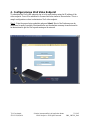
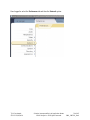
4. Configure Avaya 10x0 Video Endpoint ................................................................. 27
5. Verification Steps .................................................................................................. 34

TJM Reviewed:
SPOC 12/01/2010
Solution Interoperability Lab Application Notes
©2010 Avaya Inc. All Rights Reserved.
3 of 45
SM6_CMFS6_10x0
5.1. Verify Avaya Aura
TM
Session Manager Configuration ........................................... 34
5.1.1. Verify Avaya Aura
TM
Session Manager is Operational ..................................... 34
5.1.2. Verify SIP Link Status ....................................................................................... 36
5.1.3. Verify Registrations of SIP Endpoints ............................................................... 37
5.2. Verify Avaya Aura
TM
Communication Manager Feature Server Configuration ...... 39
5.3. Call Scenarios Verified ......................................................................................... 42
6. Acronyms .............................................................................................................. 43
7. Conclusion ............................................................................................................ 43
8. Additional References ........................................................................................... 43

TJM Reviewed:
SPOC 12/01/2010
Solution Interoperability Lab Application Notes
©2010 Avaya Inc. All Rights Reserved.
4 of 45
SM6_CMFS6_10x0
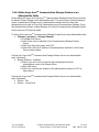
1. Introduction
These Application Notes present a sample configuration for a network that uses Avaya Aura™
Session Manager to support registration of Avaya 10x0 (1010, 1020, 1030, 1040, and 1050) SIP
Video endpoints and enables connectivity to Avaya Aura™ Communication Manager Feature
Server 6.0 using SIP trunks.
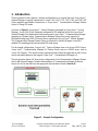
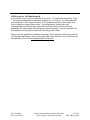
As shown in Figure 1, Avaya Aura™ Session Manager is managed by Avaya Aura™ System
Manager. Avaya 10x0 Video Endpoints configured as SIP endpoints utilize the Avaya Aura™
Session Manager User Registration feature and require Avaya Aura™ Communication Manager
operating as a Feature Server. Communication Manager Feature Server only supports IP
Multimedia Subsystem (IMS)-SIP users that are registered to Avaya Aura™ Session Manager.
The Communication Manager Feature Server is connected to Session Manager via an IMS-
enabled SIP signaling group and associated SIP trunk group.
For the sample configuration, Avaya Aura™ Session Manager runs on an Avaya S8510 Server.
Avaya Aura™ Communication Manager 6.0 Feature Server runs on a S8800 server with an
Avaya 450 Gateway. The results in these Application Notes should be applicable to other Avaya
servers and media gateways that support Avaya Aura™ Communication Manager 6.0.
These Application Notes will focus on the configuration of the Communication Manager Feature
Server and Session Manager. Detailed administration of Communication Manager Evolution
Server will not be described (see the appropriate documentation listed in Section 8).
Figure 1 – Sample Configuration

TJM Reviewed:
SPOC 12/01/2010
Solution Interoperability Lab Application Notes
©2010 Avaya Inc. All Rights Reserved.
5 of 45
SM6_CMFS6_10x0
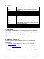
1.1. Equipment and Software Validated
The following equipment and software were used for the sample configuration.
Equipment Software
Avaya Aura
TM
Session Manager Release 6.0.0.0.600020
Avaya Aura
TM
System Manager Release 6.0 Load: 6.0.0.0.11
Avaya Aura
TM
Communication Manager
• Avaya S8800 Server Feature Server
Release R016x.00.0.345.0-2350
Avaya IP Telephones10x0 Video Endpoints (SIP):
• 1020
• 1030
• 1040
FW: AV_PP1_4.7.0 (19)2.0
FW:3.0 AV_EX2_4.7.0 (19)
FW:1.5 AV_TM2_4.7.0 (19)
2. Configuring Avaya Aura
TM
Communication Manager
Feature Server
This section describes the administration of Communication Manager Feature Server using a
System Access Terminal (SAT). Alternatively, some of the station administration could be
performed using the Communication System Management application on System Manager.
These instructions assume the G450 Media Gateway is already configured on the
Communication Manager Feature Server. Some administration screens have been abbreviated for
clarity.
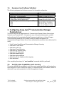
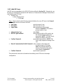
Verify System Capabilities and Communication Manager Licensing
Administer IP node names
Administer codec type
Administer IP network region
Administer SIP signaling group
Administer SIP trunk group
Administer numbering plan
Administer station endpoints
Administer off-pbx-telephone station-mapping
Save translations
After completing these steps, the “save translation” command should be performed
.
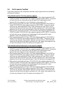
2.1. Verify System Capabilities and Licensing
This section describes the procedures to verify the correct system capabilities and licensing have
been configured. If there is insufficient capacity or a required feature is not available, contact an
authorized Avaya sales representative to make the appropriate changes.

TJM Reviewed:
SPOC 12/01/2010
Solution Interoperability Lab Application Notes
©2010 Avaya Inc. All Rights Reserved.
6 of 45
SM6_CMFS6_10x0
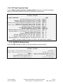
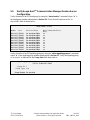
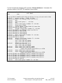
2.1.1. SIP Trunk Capacity Check
Issue the display system-parameters customer-options command to verify that an adequate
number of SIP trunk members are licensed for the system as shown below:
display system-parameters customer-options Page 2 of 11
OPTIONAL FEATURES
IP PORT CAPACITIES USED
Maximum Administered H.323 Trunks: 12000 0
Maximum Concurrently Registered IP Stations: 18000 0
Maximum Administered Remote Office Trunks: 12000 0
Maximum Concurrently Registered Remote Office Stations: 18000 0
Maximum Concurrently Registered IP eCons: 414 0
Max Concur Registered Unauthenticated H.323 Stations: 100 0
Maximum Video Capable Stations: 18000 0
Maximum Video Capable IP Softphones: 18000 0
Maximum Administered SIP Trunks: 24000 128
Maximum Administered Ad-hoc Video Conferencing Ports: 24000 50
Maximum Number of DS1 Boards with Echo Cancellation: 522 0
Maximum TN2501 VAL Boards: 128 0
Maximum Media Gateway VAL Sources: 250 0
Maximum TN2602 Boards with 80 VoIP Channels: 128 0
Maximum TN2602 Boards with 320 VoIP Channels: 128 0
Maximum Number of Expanded Meet-me Conference Ports: 300 0
(NOTE: You must logoff & login to effect the permission changes.)
2.1.2. AAR/ARS Routing Check
Verify that ARS is enabled (on page 3 of system-parameters customer options)
display system-parameters customer-options Page 3 of 11
OPTIONAL FEATURES
A/D Grp/Sys List Dialing Start at 01? n CAS Main? n
Answer Supervision by Call Classifier? n Change COR by FAC? n
ARS? y Computer Telephony Adjunct Links? y
ARS/AAR Partitioning? y Cvg Of Calls Redirected Off-net? y
ARS/AAR Dialing without FAC? y DCS (Basic)? y
ASAI Link Core Capabilities? y DCS Call Coverage?

TJM Reviewed:
SPOC 12/01/2010
Solution Interoperability Lab Application Notes
©2010 Avaya Inc. All Rights Reserved.
7 of 45
SM6_CMFS6_10x0
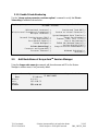
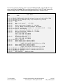
2.1.3. Enable Private Numbering
Use the “change system-parameters customer-options” command to verify that Private
Networking is enabled as shown below:
display system-parameters customer-options Page 5 of 11
OPTIONAL FEATURES
Multinational Locations? y Station and Trunk MSP? y
Multiple Level Precedence & Preemption? n Station as Virtual Extension? y
Multiple Locations? y
System Management Data Transfer? n
Personal Station Access (PSA)? y Tenant Partitioning? n
PNC Duplication? n Terminal Trans. Init. (TTI)? y
Port Network Support? n Time of Day Routing? n
Posted Messages? n TN2501 VAL Maximum Capacity? y
Uniform Dialing Plan? y
Private Networking? y Usage Allocation Enhancements? y
Processor and System MSP? y
Processor Ethernet? y Wideband Switching? n
Wireless? y
2.2. Add Node Name of Avaya Aura
TM
Session Manager
Using the change node-names ip command, add the node-name and IP for the Session
Manager’s software asset, if not previously added.
change node-names ip Page 1 of 2
IP NODE NAMES
Name IP Address
default 0.0.0.0
procr 135.9.88.72
procr6 ::
silasm4 135.9.88.62

TJM Reviewed:
SPOC 12/01/2010
Solution Interoperability Lab Application Notes
©2010 Avaya Inc. All Rights Reserved.
8 of 45
SM6_CMFS6_10x0
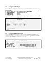
2.3. Configure Codec Type
Issue the change ip-codec-set n command where “n” is the next available number. Enter the
following values:
Enter “G.711MU” and “G.729” as supported types of Audio Codecs
Silence Suppression: Retain the default value “n”.
Frames Per Pkt: Enter “2”.
Packet Size (ms): Enter “20”.
Media Encryption: Enter the value based on the system requirement. For the sample
configuration “none” was used.
change ip-codec-set 1 Page 1 of 2
IP Codec Set
Codec Set: 1
Audio Silence Frames Packet
Codec Suppression Per Pkt Size(ms)
1: G.711MU n 2 20
2: G.729 n 2 20
3:
Media Encryption
1: none
2.4. Configure IP Network Region
Using the change ip-network-region 1 command, set the Authoritative Domain. For the
sample configuration “dr.avaya.com” was used. Verify the Intra-region IP-IP Direct Audio,
and Inter-region IP-IP Direct Audio fields are set to yes.
change ip-network-region 1 Page 1 of 19
IP NETWORK REGION
Region: 1
Location: 1 Authoritative Domain: dr.avaya.com
Name: CMFS-Video
MEDIA PARAMETERS Intra-region IP-IP Direct Audio: yes
Codec Set: 1 Inter-region IP-IP Direct Audio: yes
UDP Port Min: 2048 IP Audio Hairpinning? n
UDP Port Max: 16585

TJM Reviewed:
SPOC 12/01/2010
Solution Interoperability Lab Application Notes
©2010 Avaya Inc. All Rights Reserved.
9 of 45
SM6_CMFS6_10x0
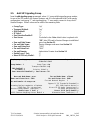
2.5. Add SIP Signaling Group
Issue the add signaling-group n command, where “n” is an available signaling group number,
for one of the SIP trunks to the Session Manager, and fill in the indicated fields. In the sample
configuration, trunk group “1” and signaling group “1” were used to connect to Avaya Aura™
Session Manager. Default values can be used for the remaining fields.
Group Type: “sip”
Transport Method: ”tcp”
IMS Enabled?: “y”
IP Video?: “y”
Peer Detection Enabled?: “y”
Peer Server: Use default value. Note: default value is replaced with
“SM” after SIP trunk to Session Manager is established
Near-end Node Name: procr from Section 2.2
Far-end Node Name: Session Manager node name from Section 2.2
Near-end Listen Port: “5060”
Far-end Listen Port: “5060”
Far-end Domain: Authoritative Domain from Section 2.4
Enable Layer 3 Test: “y”
Direct IP-IP Early Media?: “y”
display signaling-group 1 Page 1 of 1
SIGNALING GROUP
Group Number: 1 Group Type: sip
Transport Method: tcp
IMS Enabled? y
IP Video? y Priority Video? y
Peer Detection Enabled? y Peer Server: SM
Near-end Node Name: procr Far-end Node Name: silasm4
Near-end Listen Port: 5060 Far-end Listen Port: 5060
Far-end Network Region: 1
Far-end Domain: dr.avaya.com
Bypass If IP Threshold Exceeded? n
Incoming Dialog Loopbacks: eliminate RFC 3389 Comfort Noise? n
DTMF over IP: rtp-payload Direct IP-IP Audio Connections? y
Session Establishment Timer(min): 3 IP Audio Hairpinning? n
Enable Layer 3 Test? y Direct IP-IP Early Media? y
H.323 Station Outgoing Direct Media? n Alternate Route Timer(sec): 6

TJM Reviewed:
SPOC 12/01/2010
Solution Interoperability Lab Application Notes
©2010 Avaya Inc. All Rights Reserved.
10 of 45
SM6_CMFS6_10x0
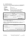
2.6. Add SIP Trunk Group
Add the corresponding trunk group controlled by this signaling group via the add trunk-group
n command, where “n” is an available trunk group number and fill in the indicated fields.
Group Type: “sip”
Group Name: A descriptive name.
TAC: An available trunk access code.
Service Type: “tie”
Signaling Group: The number of the signaling group added in Section 2.5
Number of Members: The number of SIP trunks to be allocated to calls
routed to Session Manager (must be within the limits
of the total number of trunks configured in Section 2.1.1).
add trunk-group 1 Page 1 of 21
TRUNK GROUP
Group Number: 1 Group Type: sip CDR Reports: y
Group Name: SIP Video TG to silasm4 COR: 1 TN: 1 TAC: #001
Direction: two-way Outgoing Display? y
Dial Access? n Night Service:
Queue Length: 0
Service Type: tie Auth Code? n
Signaling Group: 1
Number of Members: 64
Once the add command is completed, trunk members will be automatically generated based on
the value in the Number of Members field.
On Page 2, set the Preferred Minimum Session Refresh Interval to 1200. Note: to avoid extra
SIP messages, all SIP trunks connected to Session Manager should be configured with a
minimum value of 1200.
add trunk-group 1 Page 2 of 21
Group Type: sip
TRUNK PARAMETERS
Unicode Name: auto
Redirect On OPTIM Failure: 5000
SCCAN? n Digital Loss Group: 18
Preferred Minimum Session Refresh Interval(sec): 1200

TJM Reviewed:
SPOC 12/01/2010
Solution Interoperability Lab Application Notes
©2010 Avaya Inc. All Rights Reserved.
11 of 45
SM6_CMFS6_10x0
On Page 3, set Numbering Format to be “private”. Use default values for all other fields.
add trunk-group 1 Page 3 of 21
TRUNK FEATURES
ACA Assignment? n Measured: none
Maintenance Tests? y
Numbering Format: private
UUI Treatment: service-provider
Replace Restricted Numbers? n
Replace Unavailable Numbers? n
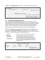
2.7. Administering Numbering Plan
SIP Users registered to Session Manager needs to be added to either the private or public
numbering table on the Communication Manager Feature Server. For the sample configuration,
private numbering was used and all extension numbers were unique within the private network.
However, in many customer networks, it may not be possible to define unique extension
numbers for all users within the private network. For these types of networks, additional
administration may be required as described in References [3] and [8] in Section 8.
To enable SIP endpoints to dial extensions defined in the Communication Manager Feature
Server, use the “change private-numbering x” command, where x is the number used to
identify the private number plan. For the sample configuration, extension numbers starting with
5-XXXX are used on the Communication Manager Feature Server.
Ext Len: Enter the extension length allowed by the dial plan
Ext Code: Enter leading digit (s) from extension number
Trunk Grp: Enter the SIP Trunk Group number for the SIP trunk
between the Feature Server and Session Manager
Private Prefix: Leave blank unless an enterprise canonical numbering
scheme is defined in Session Manager. If so, enter the
appropriate prefix.
change private-numbering 1 Page 1 of 2
NUMBERING - PRIVATE FORMAT
Ext Ext Trk Private Total
Len Code Grp(s) Prefix Len
5 5 1 5 Total Administered: 1
Maximum Entries: 540

TJM Reviewed:
SPOC 12/01/2010
Solution Interoperability Lab Application Notes
©2010 Avaya Inc. All Rights Reserved.
12 of 45
SM6_CMFS6_10x0
2.8. Configure Stations
The method is the same for administering all of the Avaya 1000 series video endpoints with the
exception of the 1040 and 1050’s. The only difference is that the 1040 can be administered to
have up to 3 call appearances and the 1050 can have up to 7 call appearances for conferencing
via their internal MCU’s. The 1010, 1020, and 1030 have to be administered with only one call-
appearance since they are a single-line endpoint with no conferencing or transferring capabilities.
For each SIP user to be defined in Session Manager, add a corresponding station on the
Communication Manager Feature Server. Note: instead of manually defining each station using
the Communication Manager SAT interface, the preferred option is to automatically generate the
SIP station when adding a new SIP user. See Section 3.3.6 for more information on adding SIP
users.
The phone number defined for the station will be the number the SIP user enters to register to
Session Manager. Use the “add station x” command where x is a valid extension number
defined in the system. In this example extension 55002 is an Avaya 1020 video endpoint. On
page 1 of the change station form:
Phone Type: Set to 9630SIP
Name: Display name for user
Security Code: Number used when user logs into station. Note: this code
should match the “Shared Communication Profile
Password” field defined when adding this user in Session
Manager. See Section 3.3.6.
IP Video? Enable endpoint for video
add station 55002 Page 1 of 6
STATION
Extension: 55002 Lock Messages? n BCC: 0
Type: 9630SIP Security Code: 123456 TN: 1
Port: S00006 Coverage Path 1: 1 COR: 1
Name: SIL Video Lab - 1020 Coverage Path 2: COS: 1
Hunt-to Station:
STATION OPTIONS
Time of Day Lock Table:
Loss Group: 19
Message Lamp Ext: 55002
Display Language: english Button Modules: 0
Survivable COR: internal
Survivable Trunk Dest? y IP SoftPhone? n
IP Video? y

TJM Reviewed:
SPOC 12/01/2010
Solution Interoperability Lab Application Notes
©2010 Avaya Inc. All Rights Reserved.
13 of 45
SM6_CMFS6_10x0
Note: It is important to assign only one call-appearance for the 1010, 1020, and 1030’s.
add station 55002 Page 4 of 6
STATION
SITE DATA
Room: Headset? n
Jack: Speaker? n
Cable: Mounting: d
Floor: Cord Length: 0
Building: Set Color:
ABBREVIATED DIALING
List1: List2: List3:
BUTTON ASSIGNMENTS
1: call-appr 5:
2: 6:
3: 7:
4: 8:
On page 6, set:
SIP Trunk option: Enter SIP Trunk Group defined in Section 2.6
change station 55002 Page 6 of 6
STATION
SIP FEATURE OPTIONS
Type of 3PCC Enabled: None
SIP Trunk: 1

TJM Reviewed:
SPOC 12/01/2010
Solution Interoperability Lab Application Notes
©2010 Avaya Inc. All Rights Reserved.
14 of 45
SM6_CMFS6_10x0
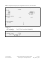
2.9. Configure Off-PBX-Telephone Station-Mapping
Use the “change off-pbx-telephone station-mapping” command for each extension associated
with SIP users defined in Session Manager. On page 1, enter the SIP Trunk Group defined in
Section 2.6 and use default values for other fields.
change off-pbx-telephone station-mapping 55002 Page 1 of 3
STATIONS WITH OFF-PBX TELEPHONE INTEGRATION
Station Application Dial CC Phone Number Trunk Config Dual
Extension Prefix Selection Set Mode
55002 OPS - 55002 1 1
-
-
On Page 2, enter the following values:
Mapping Mode: “both”
Calls Allowed: “all”
change off-pbx-telephone station-mapping 55002 Page 2 of 3
STATIONS WITH OFF-PBX TELEPHONE INTEGRATION
Station Appl Call Mapping Calls Bridged Location
Extension Name Limit Mode Allowed Calls
55002 OPS 1 both all none
-
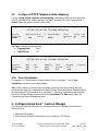
2.10. Save Translations
Configuration of Communication Manager Feature Server is complete. Use the “save
translations” command to save these changes
Note: After a change on Communication Manager Feature Server which alters the dial plan,
synchronization between Communication Manager Feature Server and Session Manager needs to
be completed and SIP phones must be re-registered. To request an on demand synchronization,
log into the System Manager console and use the Synchronize CM Data feature under the
Communication System Management menu.
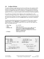
3. Configure Avaya Aura™ Session Manager
This section provides the procedures for configuring the Session Manager and includes the
following items:
Administer SIP domain
Define Logical/Physical Locations that can be occupied by SIP Entities

TJM Reviewed:
SPOC 12/01/2010
Solution Interoperability Lab Application Notes
©2010 Avaya Inc. All Rights Reserved.
15 of 45
SM6_CMFS6_10x0
For each SIP entity in the sample configuration:
o Define SIP Entity
o Define Entity Links, which define the SIP trunk parameters used by Avaya
Aura ™ Session Manager when routing calls to/from SIP Entities
o Define Routing Policies, which control call routing between the SIP Entities
o Define Dial Patterns, which govern to which SIP Entity a call is routed
Define the Communication Manager Feature Server as an Managed Element
Adding SIP Endpoints/SIP URE users
Configuration is accomplished by accessing the browser-based GUI of Avaya Aura™ System
Manager, using the URL “http://<ip-address>/SMGR”, where “<ip-address>” is the IP address of
Avaya Aura™ System Manager.
Log in with the appropriate credentials and accept the Copyright Notice.
Expand the Routing Link on the left side of Navigation Menu. Select a specific item such as
Domains.
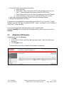
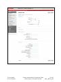
3.1. Administer SIP Domains
Expand Routing and select Domains.
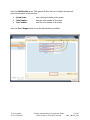
Click New
In the General Section, under Name add a descriptive name. Under Notes add a brief
description.
Click Commit to save.
The screen below shows the information for the sample configuration.

TJM Reviewed:
SPOC 12/01/2010
Solution Interoperability Lab Application Notes
©2010 Avaya Inc. All Rights Reserved.
16 of 45
SM6_CMFS6_10x0
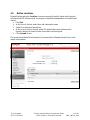
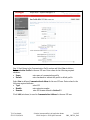
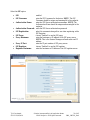
3.2. Define Locations
Expand Routing and select Locations. Locations are used to identify logical and/or physical
locations where SIP Entities reside, for purposes of bandwidth management or location-based
routing.
Click New
In the General Section, under Name add a descriptive name.
Under Notes add a brief description.
In the Location Pattern Section, under IP Address Pattern enter pattern used to
logically identify the location Under Notes add a brief description.
Click Commit to save.
The screen below shows the information for Communication Manager Feature Server in the
sample configuration.

TJM Reviewed:
SPOC 12/01/2010
Solution Interoperability Lab Application Notes
©2010 Avaya Inc. All Rights Reserved.
17 of 45
SM6_CMFS6_10x0
3.3. Add Avaya Aura
TM
Communication Manager Feature Server
The following section captures relevant screens for defining Avaya Aura
TM
Communication
Manager Feature Server applicable for the sample configuration.
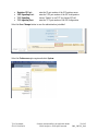
3.3.1. Define a SIP Element for Avaya Aura
TM
Communication Manager
Feature Server
The following screen shows addition of Communication Manager Feature Server. The IP
address used is that of the Processor Ethernet (procr) of the Avaya Communication Manager
Feature server.

TJM Reviewed:
SPOC 12/01/2010
Solution Interoperability Lab Application Notes
©2010 Avaya Inc. All Rights Reserved.
18 of 45
SM6_CMFS6_10x0
3.3.2. Define Element Link for Avaya Aura
TM
Communication Manager
Feature Server
The following screen shows the Element Link defined for the Avaya Aura
TM
Communication
Manager Feature Server.
3.3.3. Define Routing Policy for Avaya Aura
TM
Communication Manager
Feature Server
Since the SIP users are registered on Session Manager, a routing policy does not need to be
defined for the Communication Manager Feature Server.

TJM Reviewed:
SPOC 12/01/2010
Solution Interoperability Lab Application Notes
©2010 Avaya Inc. All Rights Reserved.
19 of 45
SM6_CMFS6_10x0
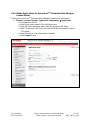
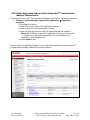
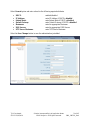
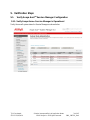
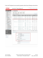
3.3.4. Define Applications for Avaya Aura
TM
Communication Manager
Feature Server
To define the Avaya Aura
TM
Communication Manager Feature Server Applications,
Elements -> Session Manager, Application Configuration Applications
o Click New (Not shown)
o Under Name, enter a name for the Application entry
o Under SIP Entity drop-down menu, select the appropriate SIP Entity.
o Under CM System for SIP Entity, this field can be left as the default of Select
CM System.
o Under Description, enter a description if desired.
o Click Commit to save.

TJM Reviewed:
SPOC 12/01/2010
Solution Interoperability Lab Application Notes
©2010 Avaya Inc. All Rights Reserved.
20 of 45
SM6_CMFS6_10x0
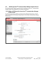
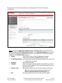
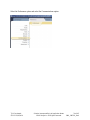
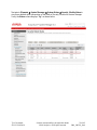
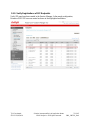
3.3.5. Define Application Sequences for Avaya Aura
TM
Communication
Manager Feature Server
To define the Avaya Aura
TM
Communication Manager Feature Server Application Sequences,
Elements -> Session Manager, Application Configuration Application
Sequences
o Click New (Not shown)
o Under Name, enter a name of the Application Sequence.
o Under Description, enter a description if desired.
o Under Available Applications, select the Application that was created in
Section 3.3.4. The way to select the Application of choice is to click on the
“+” symbol next to the Application desired. This will be added to the
Applications in this Sequence list.
o Click Commit to save.
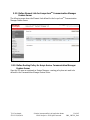
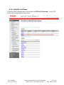
Second, define an Application Sequence for call application sequencing in the Avaya Aura
TM
Communication Manager Feature Server as shown below:
Page is loading ...
Page is loading ...
Page is loading ...
Page is loading ...
Page is loading ...
Page is loading ...
Page is loading ...
Page is loading ...
Page is loading ...
Page is loading ...
Page is loading ...
Page is loading ...
Page is loading ...
Page is loading ...
Page is loading ...
Page is loading ...
Page is loading ...
Page is loading ...
Page is loading ...
Page is loading ...
Page is loading ...
Page is loading ...
Page is loading ...
Page is loading ...
Page is loading ...
-
 1
1
-
 2
2
-
 3
3
-
 4
4
-
 5
5
-
 6
6
-
 7
7
-
 8
8
-
 9
9
-
 10
10
-
 11
11
-
 12
12
-
 13
13
-
 14
14
-
 15
15
-
 16
16
-
 17
17
-
 18
18
-
 19
19
-
 20
20
-
 21
21
-
 22
22
-
 23
23
-
 24
24
-
 25
25
-
 26
26
-
 27
27
-
 28
28
-
 29
29
-
 30
30
-
 31
31
-
 32
32
-
 33
33
-
 34
34
-
 35
35
-
 36
36
-
 37
37
-
 38
38
-
 39
39
-
 40
40
-
 41
41
-
 42
42
-
 43
43
-
 44
44
-
 45
45


Avaya 1000 Series Video Conferencing Systems Application Note
- Category
- Gateways/controllers
- Type
- Application Note
Ask a question and I''ll find the answer in the document
Finding information in a document is now easier with AI
Related papers
-
Avaya 1100-Series User manual
-
-
-
-
-
-
-
-
-
Other documents
-
 Cobzorb CZP-Box User manual
-
Crestron CCS-UC-1 Configuration Guide
-
-
-
Vertical Xcelerator IP IP2007 Install Manual
-
Crestron DSP-1282 Configuration Guide
-
 Avia Tablet Accessory Avaya Custom Edition User manual
-
Poly Trio 8500 Deployment Guide
-
-
Revolabs 500 PBX User manual

