Page is loading ...

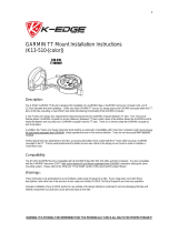
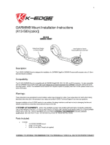
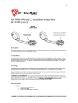
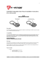
GO Big Mount Installation Instructions
(K13-440, 450, 460)
Description:
The K-Edge GO BIG ¼”-20 Mount series is designed for installation of a camera with a ¼”-20 universal mount to virtually any
surface.
Compatibility:
The K13-440 GO BIG ¼”-20 Pro Handlebar series is designed to attach any camera with the standard universal mount in front of
bicycle handlebars, out of the way of your hands and your vision.
The K13-450 GO BIG ¼”-20 Adapter mount is designed to attach any camera with the standard universal mount directly to our
original GO BIG Mounts (K13-400, 410, 420, 430) allowing mounting to virtually any surface*.
The K13-460 GO BIG ¼”-20 Saddle Rail is designed to attach any camera with the standard universal mount OR GoPro / GARMIN
VIRB (with GARMIN supplied adapter) mounting system to rails underneath a bicycle saddle.
* Use K13-450 adapter in combination with K13-400 (the K13-400 is also equipped on K13-420, 430, and 460) to mount on flat
surfaces (i.e. walls, skis, snowboards, cars, etc.) using either industrial double sided adhesive or screws/bolts (hardware not
included). In certain situations, caution is strongly advised to ensure proper mounting and safety.
Warnings:
These instructions are generalized to accommodate a wide ranges of setups for a bike. If your setup does not match what is being
described, take extra care in the process of your setup and contact K-Edge Support if you have any questions.
Improper installation of any K-Edge product or use outside of its design intentions could lead not only to damaging the bike but could
also cause personal injury to the rider.

Parts Included:
K13-440
1x GO BIG ¼”-20 Pro Handlebar mount
1x ¼”-20 Thumbscrew w/ head Keyed to 5mm Hex
1x Silicone O-Ring (Orange) Dash #107
1x M2.5 x 0.45 x 5mm SHCS ‘Alignment Bolt’
2x M4 x 12mm SHCS ‘Clamp Bolts’
K13-450: (Adapter Only – GO BIG Mounts Required)
1x GO BIG ¼”-20 Adapter mount
1x ¼”-20 Thumbscrew w/ head Keyed to 5mm Hex
1x Silicone O-Ring (Orange) Dash #107
1x M2.5 x 0.45 x 5mm SHCS ‘Alignment Bolt’
K13-460
1x GO BIG Pro Saddle Rail mount
1x GO BIG ¼”-20 Adapter mount
1x ¼”-20 Thumbscrew w/ head Keyed to 5mm Hex
1x Silicone O-Ring (Orange) Dash #107
1x M2.5 x 0.45 x 5mm SHCS ‘Alignment Bolt’
2x M4 x 8mm FHCS
2x M5 x 16mm FHCS
Tools/Items Required:
Metric Allen Set (3mm for clamp bolts, 4mm for mounting bolts, and 5mm for Thumbscrews)
Torque wrench
Note: (Applies to: K13-400/410/420/430/460) Prior to installation please ensure that the camera mounting bolt is installed
correctly.

Installation Steps:
Note: Prior to installation please ensure that the camera mounting bolt is installed correctly.
K13-440 (Pictured Below):
NOTE REGARDING ALIGNMENT BOLT:
Some cameras have alignment hole(s) to prevent rotation and maintain alignment. This ‘alignment hole’ can be seen
next to the ¼”-20 tapped hole on your camera. If you have this hole (located directly behind the ¼”-20 tapped hole - you
can use the supplied alignment bolt with your mount. If you do not have this ‘alignment hole’, or is not in the desired
position, remove the alignment bolt and install it on the opposite side of the mounting arm (same side as the head of the
thumbscrew)
1. Place the mount on the handlebars in the desired location (clamp separation may be necessary).
2. Torque the clamp bolts to 2 N-m, maintaining equal spacing between each bolt to ensure the bolts are evenly torqued.
3. Attach a compatible camera with a ¼”-20 universal mount to the mount with the ¼”-20 Thumbscrew.
4. Tighten by hand.
5. Adjust to desired position
6. Torque the ¼”-20 Thumbscrew according to the manufacturer’s recommendation for the given camera.
NOTE: The K13-440 is designed to allow a camera mounting position either on top of the arm or below (default),
personal preference will dictate installation procedure.

K13-450 (Pictured Below):
NOTE REGARDING ALIGNMENT BOLT:
Some cameras have alignment hole(s) to prevent rotation and maintain alignment. This ‘alignment hole’ can be seen
next to the ¼”-20 tapped hole on your camera. If you have this hole (located directly behind the ¼”-20 tapped hole - you
can use the supplied alignment bolt with your mount. If you do not have this ‘alignment hole’, or is not in the desired
position, remove the alignment bolt and install it on the opposite side of the mounting arm (same side as the head of the
thumbscrew)
1. Attach a compatible camera with a ¼”-20 universal mount to the mount with the ¼”-20 Thumbscrew.
2. Tighten by hand.
3. Adjust to desired position
4. Torque the ¼”-20 Thumbscrew according to the manufacturer’s recommendation for the given camera.
5. Attach the K13-450 adapter to a compatible Go Big Mount.

K13-460 (Pictured Below):
1. Follow the instructions for the K13-450 on the previous page to install camera.
Note: If the saddle bolts on the K13-430 do not have thread lock applied to threads, it is strongly recommended
that 'temporary' thread lock be applied to these threads.
1. Attach the saddle mount to the rails underneath the saddle.
2. Torque the bolts to 4 N-m.
3. Attach the K13-450 to the corresponding interface on the saddle mount in the desired direction.
4. Torque camera mounting bolt to 2-3 N-m. See image below:

Troubleshooting:
Camera mounting bolt is tight but camera itself is still loose (i.e. rotates/pitches easily).
o Check that the camera mounting bolt is installed in the right direction (see initial note in 'Installation Steps' section).
***If the bolt is installed incorrectly the bolt will 'bottom-out' and the head of the bolt will 'strip-out' or break while the
camera is installed but the camera will not have its pitch locked.
GO BIG handlebar mount isn’t evenly mounted on handlebars.
o Check the clamp bolts for proper torque.
o Check the clamp bolts for spacing between the clamp halves to ensure the clamp is equally torqued on both bolts.
o Check that the clamp is not mounted on a tapered portion of the handlebars.
Camera won’t adjust direction when using the saddle mount.
o Check the positioning of the saddle mount for contact between the saddle and camera.
If there is contact, adjust the saddle mount further down the rails.
Support/Contact:
If problem(s) still persist after troubleshooting, please contact K-Edge Support for further assistance at info@K-Edge.com
immediately. Please be sure to include your full name, phone number, K-Edge product purchased, brand and model of bike,
crankset with ring sizes, front derailleur, cassette size (if applicable), rear derailleur (if applicable) and a brief description of your
problem.
/