Page is loading ...

696-16-INST-Imp&Metric
5/22
Installation Manual
Model 696
100 & 110 Gallon Preservative Applicator
Forage Harvester

2
DECLARATION OF INCORPORATION
MANUFACTURER: Harvest Tec LLC.
2821 Harvey St.
P.O. Box 63
Hudson, WI 54016, U.S.A.
REPRESENTATIVE ESTABLISHED IN COMMUNITY: Profitable Farming Company
Middle Barlington, Roborough
Winkleigh, Devon, EX19 8AG
ENGLAND
The person above certifies and declares that:
VIRTUAL MACHINE: Equipment mounted on a farm press and for the application of innoculants onto forage crops.
MODEL: 696-INST-19-Imp&Metric
BRAND: Harvest Tec
SERIAL NUMBER:
This application preservatives for hay Harvest Tec system meets the Directive 2006/42/EC of the European Parliment and
the Council of 17 May 2006 and other applicable European Directives including Directive 2004/108/EC on the
Electromagnetic compatability.
The application of preservatives for hay Harvest Tec system will be turned on after being installed on a farm press has been
declard in conformity with the Machinery Directive.
Person in the community authorized to provide information on the partly completed machinery and making this statement:
Richard Snell, President, Profitable Farming Company
Signed on May 21, 2011: Middle Barlington, Roborough
Winkleigh, Devon, EX19 8AG
ENGLAND

3
Harvest Tec Model 696 Installation Table of Contents
PAGE
Introduction
5
System Requirements
5
Installation Kit Reference Chart
5-6
Tools Needed
6
Installation of Applicator
7-45
Installation of Pump Manifold
7-10
Hesston, New Idea, Challenger, Massey Ferguson & CASE IH 8570,
8575, 8580, 8585, & 8590 Balers
7
Case IH & New Holland
8
Claas, John Deere, Vermeer, & Krone Balers
9
Claas 3200 – 3400 Large Square Balers
10
Kuhn, Vicon, & Taarup balers
11
Installation of Dual Channel Processor (DCP)
12
Installation of Tank and Star Wheels
13-21
New Holland 590 - BB 9080 & Case IH LBX331 through LB433 Baler
14
Case IH 8570, 8575, & 8585, Challenger LB33, LB34, & Hesston 7430,
4750, 4755, 4760, 4790, & Massey Ferguson 2050, & New Idea 7233,
7333, & 7234 Balers
15
Case IH 8580, 8590 & Hesston 4900, 4910 & Challenger LB 44 & New
Idea 7244
16
Vermeer Balers
17
Claas 2100 & 2200 Balers
18
Claas 3200-3400 Large Square Balers
18-19
Krone Balers
20
Kuhn 870 – 1290, Vicon LB 8200 & LB 12200 balers & Taarup 6570 –
6690 OC
21
Installation of End of Bale Sensor (EOB)
22-32
Hesston 4760, 4750-4755, 4790 & 4900-4910
22
Krone 890 – 12130
23
All Kuhn, Vicon & Taarup Balers
23
EOB Installation Diagram
24-32
Hesston 4750-4755 & 4900-4910
24
Heston 4760 & 4790
25
New Holland 590-BB960, BB9060-BB9080 & Case IH LBX 331-431,
LB333-LB433
26
New Holland BB940A-BB960A & Case IH LBX 332-432
27
Claas 2100
28
John Deere 100
29
Krone 890 – 1290
30
Krone 12130
31
All Kuhn, Vicon and Taarup Balers
32
Installation of Drain/Fill Line
33
Installation of Spray Shield
34-46
High /Low Tip Output Rates
34
Installation kit 4438B
34
Installation kit 4439B & 4490B
35
Installation kit 4491B & 4492B
36
Installation kit 4494B, 4495B & 4528B
37
Installation kit 4497B & 4529B
38
Installation kit 4498B
38
Installation kit 4499B & 4500B
39

4
Table of Contents (continued)
PAGE
Installation kit 4501B & 4509B
40
Installation kit 4510B & 4511B
41
Installation kit 4514B & 4515B
42
Installation kit 4525B & 4537B
43
Installation kit 4539B, 4540 & 4541B
44
Installation kit 4540BX
45
Installation kit 4541BX
46
Plumbing
47
High/Low Tip Selection, Hose Color, Pump Position
47
Installation of Star Wheel and Bale Rate Harness
47
Wiring Main Power /Communication Harness to Baler Terminator Connection
48
Installation of Bluetooth Receiver / Connecting optional ISOBUS Plug
48
Krone ISOBUS Integration (optional)
49
Wiring Diagram – Krone ISOBUS Integration (optional)
50
Wiring Diagram
51
Pin Outs
52-54
Parts Breakdown
55-87
Tank, Saddle and Saddle Legs
55-57
Pump Manifold
58
Star Wheel Moisture Sensor
59
Controls and Harnesses
60
Hose and Drain Fill Line
61
Optional iPad Mini Mounting Kit & Display Kit
62-63
Model Specific Installation Kits
64-87
Installation kit 4438B
64
Installation kit 4439B
65
Installation kit 4490B
66
Installation kit 4491B
67
Installation kit 4492B
68
Installation kit 4494B
69
Installation kit 4495B & 4528B
70
Installation kit 4497B & 4529B
71
Installation kit 4498B
72
Installation kit 4499B
73
Installation kit 4500B
74
Installation kit 4501B
75
Installation kit 4509B
76
Installation kit 4510B
77
Installation kit 4511B
78
Installation kit 4514B
79
Installation kit 4515B
80
Installation kit 4525B
81
Installation kit 4537B
82
Installation Kit 4539B
83
Installation Kit 4540B
84
Installation Kit 4540BX
85
Installation Kit 4541B
86
Installation Kit 4541BX
87
Vicon Star Wheel Install Template
88
Star Wheel Install Template
89
Notes
90
Warranty Statement
91

5
Introduction
Thank you for purchasing a Harvest Tec Model 696 Hay Preservative Applicator. This 696 applicator system
has been designed to be operated through an Apple iPad (not included) using the Hay App. As well as the
option to plug directly into most tractors that have an ISOBUS Monitor. The 696 Applicator System offers these
advantages by operating through an Apple iPad:
1. Large bright, clear, colorful display
2. More durable and can be read in bright sunlight
3. Can be used for multiple other uses than just the applicator display
4. Option to tie-into the tractor ISOBUS system
The 696 Hay Preservative Applicator System is designed to apply buffered propionic acid to the forage crop as
it is baled and will adjust the rate of application based on moisture and tonnage of the crop being harvested.
The model 696 base kit includes: tank, frame, pumps, hose, and the Dual Channel Processor (DCP). This
manual will take you through the steps for installing the applicator. If you are unsure about installing the system
after consulting this manual, contact your local authorized dealership for additional assistance. If you are in
need of parts for the system please see the parts breakdown in the back of this manual and contact your local
authorized dealer to order the parts. This applicator is designed to apply Harvest Tec buffered propionic acid.
Right and Left sides are determined by facing in the direction of forward travel.
*Made for iPad® running the current iOS operating system
or one version previous required for iPad option
*iPad is a trademark of Apple Inc., registered in the U.S. and other countries.
**600 Series Applicators with serial number before DCP27000 will require the DCP to be sent to Harvest
Tec for a required update in order to use the iPad Integration Module (030-6672C).
*Hay App version must be at least 2.5.18 (or higher) to operate with the iPad Integration Module
If choosing to operate the unit though the ISOBUS monitor, pn 006-6670A will need to be ordered through your
local equipment dealer. 2018 Krone balers (and beyond) Serial Number 976909 will need pn 006-6650VAK.
Attention:
For kits on 2010 Krone HDP balers and newer Krone part number 20 073 194 0 must be ordered to mount the
star wheels.
Please see attached supplemental manual for further instructions.
Installation Kit Reference Chart
BALER MAKE
MODEL
INSTALL KIT
AGCO
Hesston
4750 – 4755
4760
4790
4900 – 4910
4760 roto-cutter
4790 roto-cutter
7430
7430 roto-cutter
030-4490B
030-4494B
030-4492B
030-4491B
030-4500B
030-4501B
030-4494B
030-4500B
Case IH
8570 – 8575
8585
8580 - 8590
LBX331 – 332 STD or packer
LBX431 – 432 STD or packer
LBX331 – 332 roto-cutter
030-4490B
030-4492B
030-4491B
030-4495B
030-4495B
030-4497B

6
LBX431 – 432 roto-cutter
LB333 – 433 STD or packer
LB333 – 433 roto-cutter
LB 433 STD or packer (2011-2012)
LB 433 roto-cuter (2011-2012)
030-4497B
030-4495B
030-4497B
030-4528B
030-4529B
Challenger
LB33
LB34
LB44
030-4494B
030-4492B
030-4491B
Claas
2200/1200/3200/3400
2100
3300
030-4499B
030-4509B
030-4537B
Krone
VFS 88
VFS 88 cutter
VFS 128
VFS 128 cutter
890-12130 XC
890-12130
BP 4x4, BP 4x4 HS
890 XC High Speed
1270,1290, 1290HDP, 4x4 XC HS
030-4498B
030-4495B
030-4498B
030-4495B
030-4514B
030-4515B
030-4539B
030-4540B
030-4541B
Kuhn
LSB 870 – 890
LSB 1270 – 1290
Omni-cut
030-4510B
030-4511B
030-4525B
Massey
Ferguson
2050
2050 roto-cutter
030-4494B
030-4500B
New Idea
7233
7234
7244
7333
030-4490B
030-4492B
030-4491B
030-4494B
New Holland
590-BB9080 STD or packer
BB940-BB9080 roto-cutter
BB9080 STD or packer (2011-2012)
BB9080 roto-cutter (2011-2012)
030-4495B
030-4497B
030-4528B
030-4529B
Taarup
6570 – 6570 OC
6670 – 6690 OC
030-4510B
030-4511B
Vermeer
SQ2731
SQ3347
030-4438B
030-4439B
Vicon
LB 8200
LB 12200
030-4510B
030-4511B
Tools Needed:
- Standard wrench set
- Standard nut driver set
- Electric drill and bits
- Standard socket set
- Side cutter
- Hammer
- Crescent wrench
- Metal cutting tools
- Standard screwdriver
- Hose cutter
- Center punch

7
Installation of Applicator
Installation of Pump Manifold
Hesston, New Idea, Challenger, and Case 8570, 8575, 8580, 8585, 8590 Balers:
3 X 3 balers only
Locate parts bag 2. Install both saddle legs (001-6707C) onto the saddle (001-6707A) with eight 3/8” x 1-1/4” Bolts, locks
and flat washers. Note: the slots in the legs will attach to the second and fourth weld nuts in from each end, of the saddle,
on both sides.
1. Once legs and saddle are loosely attached measure the distance from the top outside corners of the bale
chamber where the saddle will be attached. Move legs in or out so the outside edges will match this dimension.
Also try to center the saddle within these dimensions. Do not fully tighten bolts until mounted on the baler
2. Locate parts bag 6. Mount the pump plate support legs (001-6707FL & 001-6707FR) to the saddle legs using six
3/8” x 1” bolts, locks, flats, and nuts. Note: this will be the side that is opposite of the “V” notch that is in the sump
cut out of the saddle
3. Attach the pump plate mounting bracket (001-4646C) to the pump plate support legs with two 3/8” x 1-1/4” bolts,
locks, flats, and nuts.
4. Attach the pump plate holder (001-4646D) to the pump plate mounting bracket (001-4646C) using four 3/8” x 3/4”
flange head bolts
3 X 4 and 4 x 4 balers only
Locate parts bag 2. Install both saddle legs (001-6707C) onto the saddle (001-6707A) with eight 3/8” x 1-1/4” Bolts, locks
and flat washers. Note: the slots in the legs will attach to the first and second weld nuts in from each end, of the saddle,
on both sides.
1. Once legs and saddle are loosely attached measure the distance from the top outside corners of the bale
chamber where the saddle will be attached. Move legs in or out so the outside edges will match this dimension.
Also try to center the saddle within these dimensions. Do not fully tighten down bolts until mounted on the baler.
2. Locate parts bag 6. Mount the pump plate support legs (001-6707FL & 001-6707FR) to the saddle legs using six
3/8” x 1” bolts, locks, flats, and nuts. Note: this will be the side that is opposite of the “V” notch that is in the sump
cut out of the saddle
3. Attach the pump plate mounting bracket (001-4646C) to the pump plate support legs with two 3/8” x 1-1/4” bolts,
locks, flats, and nuts.
4. Attach the pump plate holder (001-4646D) to the pump plate mounting bracket (001-4646C) using four 3/8” x 3/4”
flange head bolts
The Pump Controller and pump heads must be pointing down. Failure to mount the pump plate
assembly in this specified direction will void all warranty of the Pump Controller and pumps.
001-6707FR
001-6707FL
Pump controller

8
Case IH & New Holland
3 X 3 balers only
Locate parts bag 2. Install both saddle legs (001-6707BL & 001-6707BR) onto the saddle (001-6707A) with six
3/8” x 1-1/4” bolts, locks and flat washers. The mounting slots in the legs will attach to the second and fourth
weld nuts in from each end, of the saddle, on both sides. Note: There is a “V” shape cut out in the sump area
of the saddle. This side of the saddle should be attached to the side of the legs that have a narrower profile.
1. Once legs and saddle are loosely attached measure the distance from the top outside corners of the
bale chamber where the saddle will be attached. Move legs in or out so the inside edges will match this
dimension. Also try to center the saddle within these dimensions. Do not fully tighten down bolts until
unit is mounted on the baler.
2. Connect the pump plate mounting bracket (001-4646C) to the side of the saddle that has the wider
profile to the legs. Using two 3/8” x 1-1/4” bolts, lock & flat washers.
3. Attach the pump plate holder (001-4646D) to the pump plate mounting bracket (001-4646C) using four
3/8” x 3/4” flange head bolts
3 X 4 balers only
Install both saddle legs (001-6707DL & 001-6707DR) onto the saddle (001-6707A) with six 3/8” x 1-1/4” Bolts,
locks and flat washers. The mounting slots in the legs will attach to the first and second weld nuts in from each
end, of the saddle, on both sides. Note: There is a “V” shape cut out in the sump area of the saddle. This side
of the saddle should be attached to the side of the legs that have a narrower profile.
1. Once legs and saddle are loosely attached measure the distance from the top outside corners of the
bale chamber where the saddle will be attached. Move legs in or out so the inside edges will match this
dimension. Also try to center the saddle within these dimensions. Do not fully tighten down bolts until
unit is mounted on the baler
2. Connect the pump plate mounting bracket (001-4646C) to the side of the saddle that has the wider
profile to the legs. Using two 3/8” x 1-1/4” bolts, lock & flat washers.
3. Attach the pump plate holder (001-4646D) to the pump plate mounting bracket (001-4646C) using four
3/8” x 3/4” flange head bolts
The Pump Controller and pump heads must be pointing down. Failure to mount the pump plate
assembly in this specified direction will void all warranty of the Pump Controller and pumps.
Pump
controller

9
Claas, John Deere 100, Vermeer, and Krone Balers
3 X 3 balers only
Locate parts bag 3. Install both saddle legs (001-6706V) onto the saddle (001-6706A) with six 3/8” x 1-1/4”
bolts, locks and flat washers. The mounting slots in the legs will attach to the second and third weld nuts in
from each end, of the saddle, on both sides.
1. Once legs and saddle are loosely attached measure the distance from the top outside corners of the bale
chamber where the saddle will be attached. Move legs in or out so the inside edges will match this
dimension. Also try to center the saddle within these dimensions. Do not fully tighten down bolts until unit is
mounted on the baler.
2. Connect the pump plate mounting bracket (001-4646C) to the saddle. Using two 3/8” x 1-1/4” bolts, lock &
flat washers. Note: this will be the side that is opposite of the “V” notch that is in the sump cut out of the
saddle.
3. Attach the pump plate holder (001-4646D) to the pump plate mounting bracket (001-4646C) using four
3/8” x 3/4” flange head bolts.
3 X 4 and 4 x 4 balers only
Locate parts bag 3. Install both saddle legs (001-6706V) onto the saddle (001-6706A) with six 3/8” x 1-1/4”
bolts, locks and flat washers. The mounting slots in the legs will attach to the first and second weld nuts in from
each end, of the saddle, on both sides.
1. Once legs and saddle are loosely attached measure the distance from the top outside corners of the bale
chamber where the saddle will be attached. Move legs in or out so the inside edges will match this
dimension. Also try to center the saddle within these dimensions. Do not fully tighten down bolts until unit
is mounted on the baler.
2. Connect the pump plate mounting bracket (001-4646C) to the saddle. Using two 3/8” x 1-1/4” bolts, lock &
flat washers. Note: this will be the side that is opposite of the “V” notch that is in the sump cut out of the
saddle.
3. Attach the pump plate holder (001-4646D) to the pump plate mounting bracket (001-4646C) using four
3/8” x 3/4” flange head bolts.
The Pump Controller and pump heads must be pointing down. Failure to mount the pump plate assembly in
this specified direction will void all warranty of the Pump Controller and pumps
*If the applicator is being mounted onto a Krone 870 HDP
& 1270 or 1290 High Speed baler, two leg adapter
brackets will be needed for proper tank leg installation
(right). Part number 001-6707KV
Contact your dealership for details.
Pump controller

10
Krone 12130 & 2010 HDP Balers
Install both saddle legs (001-6707KA) onto the saddle (001-6707A) with 3/8 x 1” Bolts, locks and flat washers. The
mounting slots in the legs will attach to the first and second weld nuts in from each end, of the saddle, on both sides.
Note: There is a “V” shape cut out in the sump area of the saddle. This side of the saddle should be attached to the side
of the legs that have a narrower profile. *Install leg extensions 001-6707KB if the baler was manufactured after 2010. Pre-
2010 models do not need the extensions.
1. Once legs and saddle are loosely attached measure the distance from the top outside corners of the bale chamber
where the saddle will be attached. Move legs in or out so the inside edges will match this dimension. Also try to
center the saddle within these dimensions. Do not fully tighten down bolts until unit is mounted on the baler
2. Connect the pump plate mounting bracket (001-4646C) to the side of the saddle that has the wider profile to the legs.
Note: you will have to remove the two inside bolts and replace them with two 3/8” x 1 1/4” bolts.
3. Attach the pump plate holder (001-4646D) to the pump plate mounting bracket (001-4646C) using four 3/8” x 3/4”
flange head bolts.
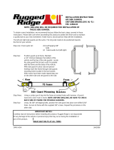
Claas 3200-3400 Large Square Balers
Tank Mounting – Prior to the installation of the tank
assembly on the baler, the factory hand rail support that
connects the hand rail to the rear tension beam must be
removed. The hardware used to mount the support to the
railing is reused when securing the handrail.
Fasten the legs (001-6706C) to the saddle (001-6706A)
using 3/8” x 1-1/4” hex bolts (x8), 3/8” lock washers, and
3/8” flat washers. The inside distance of the legs should be
approximately 48” (1.2M) Note that the tank fitting on the
side of the tank should be towards that right side of the
baler, opposite the ladder. Install the supplied rail support
(001-6706CC) to the front side of the tank saddle using
3/8”x1-1/4” hex bolts (x2), 3/8” lock washers, and 3/8” flat
washers.
Lift the tank assembly into place so it straddles the rear tension beam on top of the baler, near the end of the bale
chamber. The tank legs should rest on the top corners of the bale chamber. Slide the tank as far forward as
possible. With the tank slid as far forward as possible, attach the hand rail to the rail support (001-6706CC) using the
factory hardware. Clamp the legs to the sides of the bale chamber and drill two 9/16” (14mm) diameter holes per leg on
each side of the bale chamber. Secure the legs to the chamber with (x4) 1/2” x 1-1/2” allen head bolts, 1/2” flat washer,
1/2” lock washer, and 1/2” hex nut. At this time, the hardware securing the legs to the saddle can be loosened and
adjusted. Mount the pump plate to the rear of the tank assembly.
001-6706CC
Rail Support
001-6707KA
001-6707KB

11
Kuhn, Vicon & Taarup Balers
3 X 3 balers only
Locate parts bag 4. Install both saddle legs (001-6707BL & 001-6707BR) onto the saddle (001-6707A) with six
3/8” x 1-1/4” Bolts, locks and flat washers. The mounting slots in the legs will attach to the second and fourth
weld nuts in from each end, of the saddle, on both sides. Note: There is a “V” shape cut out in the sump area
of the saddle. This side of the saddle should be attached to the side of the legs that have a narrower profile.
1. Once legs and saddle are loosely attached measure the distance from the top outside corners of the
bale chamber where the saddle will be attached. Move legs in or out so the inside edges will match this
dimension. Also try to center the saddle within these dimensions. The spacers (001-6707BS) will be
needed between the saddle legs and frame of the baler. Do not fully tighten down bolts until unit is
mounted on the baler.
2. Connect the pump plate mounting bracket (001-4646C) to the side of the saddle that has the wider
profile to the legs. Using two 3/8” x 1-1/4” bolts, lock & flat washers.
3. Attach the pump plate holder (001-4646D) to the pump plate mounting bracket (001-4646C) using four
3/8” x 3/4” flange head bolts.
3 X 4 balers only
Locate parts bag 4. Install both saddle legs (001-6707BL & 001-6707BR) onto the saddle (001-6707A) with six
3/8” x 1-1/4” Bolts, locks and flat washers. The mounting slots in the legs will attach to the first and second
weld nuts in from each end, of the saddle, on both sides. Note: There is a “V” shape cut out in the sump area
of the saddle. This side of the saddle should be attached to the side of the legs that have a narrower profile.
1. Once legs and saddle are loosely attached measure the distance from the top outside corners of the
bale chamber where the saddle will be attached. Move legs in or out so the inside edges will match this
dimension. Also try to center the saddle within these dimensions. The spacers (001-6707BS) will be
needed between the saddle legs and frame of the baler. Do not fully tighten down bolts until unit is
mounted on the baler.
2. Connect the pump plate mounting bracket (001-4646C) to the side of the saddle that has the wider
profile to the legs. Using two 3/8” x 1-1/4” bolts, lock & flat washers.
3. Attach the pump plate holder (001-4646D) to the pump plate mounting bracket (001-4646C) using four
3/8” x 3/4” flange head bolts
The Pump Controller and pump heads must be pointing down. Failure to mount the pump plate assembly in
this specified direction will void all warranty of the Pump Controller and pumps.
Pump
controller
Spacer

12
Installation of Dual Channel Processor (DCP)
Follow the instructions below to mount the Dual Channel Processor (DCP) onto your specific baler model and
type. The locations shown are the right twine box (looking at the back of the baler). Mark and drill the four 3/8”
holes and install DCP with two 5/16” x 1” bolts, two 5/16” x 1-1/4” bolts, locks, fender washers and hex nuts. If
your baler is not listed below mount the DCP on the back of the twine box on the right side. Mount the DCP
cover over the top of the tip and secure with the hardware using the 5/16” x 1-1/4” bolts on the top with the
DCP shield.
John Deere L330 / L340 Baler DCP location on the back of the right twine box will vary slightly depending on
placement of safety decals from factory. Do not cover safety decals. Mount DCP on the back of right hand
twine box using Figure 2 as a reference. DCP location is recommended 5” (12.5cm) from inside edge and 5”
(12.5cm) from top of twine box.
Baler Type
Model
Fig.
A
B
C
Baler
Type
Model
Fig.
A
B
C
Case IH
LBX 331-
431
1
4”
(10cm)
2”
(51mm)
N/A
Hesston
4750 –
4755
1
16”
(40cm)
2”
(51mm)
N/A
Case IH
LBX
332–432
& LB
333-433
1
N/A”
2”
(51mm)
2”
(51mm)
Hesston
4760
1
2”
(51mm)
2”
(51mm)
N/A
Challenger
LB 33
1
2”
(51mm)
2”
(51mm)
N/A
Hesston
4790
1
4”
(10cm)
2.5”
(64mm)
N/A
Challenger
LB34
1
4”
(10cm)
2.5”
(64mm)
N/A
Hesston
4800 –
4910
1
16”
(40cm)
2”
(51mm)
N/A
Challenger
LB44
1
16”
(40cm)
2”
(51mm)
N/A
John
Deere
100
1
18”
(45cm)
6.5”
(16cm)
N/A
Claas
2100
1
4”
(10cm)
2”
(51mm)
N/A
Krone
890 –
12130
1
3”
(70mm)
4”
(10cm)
N/A
Claas
3300
1
4”
(10cm)
2”
(51mm)
N/A
Massey
Ferguson
2050
1
2”
(51mm)
2”
(51mm)
N/A
New
Holland
590 –
BB940
1
4”
(10cm)
2”
(51mm)
N/A
Kuhn, Vicon
Taarup
all
1
4”
(10cm)
4”
(10cm)
N/A
New
Holland
BB940A
–
960A &
BB9060 –
BB9080
1
N/A
2”
(51mm)
2”
(51mm)
Figure 1
Figure 2

13
Installation of Tank and Star Wheel Moisture Sensors
Use the drawing located in the back of this manual as a guide for cutting a notch and locating the mounting
holes for the star wheels. Carefully mark the location of the star wheel holes using the template and a center
punch so the star wheels will run true to the direction of the bales, otherwise, the star wheels may work
themselves out of the block, damaging the sensor itself or the bale rate sensors. +
The star wheels must be mounted so that they are no closer than 3/8” (10mm) from any metal parts of the
baler and come in contact only with the bale. 5/16” Allen headed bolts will be used to mount the star wheel
block and twine guard to the baler. The bolts must be inserted from the inside of the baler chamber. Use nuts
and lock washers to hold the bolts in place before putting on the star wheel block, the block is counter-bored
on one side so the block will fit over the nuts.
The star wheel block has a plug on one side and a wire grommet on the other side. If there are interference
problems with the star wheel wires on one side of the block, exchange the wire grommet with the plug so the
wire can exit the block on the other side. Mount the twine guards using the two inner holes on the star wheel
block. The twine guard containing the bale rate sensors should be placed on the baler’s right side, when
looking from the back of the baler.
*Claas Quadrant 3200 – 3400 balers will mount star wheels on side of bale chamber.
Refer to page 19 for instructions.
The following pages will contain detailed instructions for your baler. Please refer to the table of
contents for you exact listing.

14
New Holland 590 through BB9080 and Case IH LBX331 through LB433 Balers
Tank Mounting-Locate parts bag A & 2. Mount the tank legs and saddle on the baler as shown below. The
tank legs bolt to the baler with six 1/2” x 1-3/4” carriage bolts, lock & flat washers, and hex nuts. Depending on
the baler model, 9/16” (14mm) holes (3 per side) may need to be drilled in the baler to bolt down the tank legs.
The bolts should be inserted from inside the baler.
The saddle is intentionally tipped forward by 5o so that the tank cap will be parallel to the ground. There is a
small cut out “V” where the tank sump fits in the saddle and this cut out should face the back of the baler for
the tank to be level when installed on the baler.
Star Wheel Mounting-Use the template located in the back of the manual as a guide for cutting the notch and
mounting holes for the star wheels. The star wheels are to be mounted on top of the baler, just behind the
knotters and under the walkway on both sides. Remove the bale from the chute, tip the walkway up and locate
the wheels on the top outside corner angles of the bale chute, one on each side. Some balers may already
have the notch cut and square holes. If so, the holes will need to be drilled round with a 5/16” drill bit. A 1/2” x
1/2” cut may also need to be made at the base of the twine arm mounting bracket for the star wheel to sit
correctly on the bale chamber. Mark the location of the notch 5/8” wide and 9” long (16mm x 23cm) and the
location of the four 5/16” (8mm) holes for the star wheel base. After cutting the notch and drilling the hole,
insert the 5/16” x 3” x black allen head bolts up through the chute and use nuts to hold the bolts in place.
Place the star wheel block over the nuts and install the twine guards using the two inner holes of the star wheel
block. The twine guard containing the bale rate sensors will be placed on the right side. See Step 8 for
directions on how to hook-up the star wheel wires.
Star wheel
with catwalk open
Applicator shown on
four foot wide baler.

15
Case IH 8570, 8575, and 8585, Challenger LB33, LB34, and Hesston 7430, 4750, 4755, 4760, and 4790,
and Massey Ferguson 2050, and New Idea 7233, 7333, 7234 Balers
Tank Mounting- Locate parts bag A & 2. Mount the tank legs and saddle on the baler as shown below, centered
between the compression arm and the crossbeam. The tank legs bolt to the baler with six 1/2” x 1-3/4” carriage bolts,
locks & flat washers and hex nuts. Depending on the baler model, 9/16” holes (3 per side) may need to be drilled in the
baler to bolt down the tank legs. The bolts should be inserted from inside the baler.
The saddle is intentionally tipped forward by 5o so that the tank cap will be parallel to the ground. There is a small cut out
“V” where the tank sump fits in the saddle and this cut out should face the back of the baler for the tank to be level when
installed on the baler.
Star Wheel Mounting – The star wheels are mounted under the walkway on top of the baler behind the knotters.
Remove the bale from the chute and tip the walkway up. Locate the star wheel template on the outside corner angles of
the bale chute on the left and right side of the baler. The center of the wheel shaft will be approximately 5-1/2” (13cm) in
front of the walkway support or about halfway between the walkway support and the cross frame almost directly in front of
it. The notch will start just in front of the walkway support.
Two parts of the baler frame will have to be trimmed off on both sides to mount each star wheel. The first is the outside
corner angles of the chute. Use the template to mark the location of the star wheel notch as well as the location of the
four holes for the star wheel base. The notch will be 5/8” by 9” (16mm x 23cm) long and will help keep the wheel away
from the twine. Spray the ground off areas with touch up paint to prevent rusting. The second portion of the baler to trim
off is the end of the gusset that may interfere with the star wheel’s plastic base support. Center the star wheel in the slots
that was just notched and check for interference with the gusset.
Drill 5/16” (8mm) holes for the star wheel block. Insert the 5/16” x 3” bolts up through the chute and use nuts to hold the
bolts in place. Place the star wheel block over the nuts and install the twine guards using the two inner holes of the star
wheel block. The twine guard containing the bale rate sensors will be placed on the right side of the baler. See
Step 8 for directions on how to hook-up the star wheel wires.
Star wheel
with catwalk open
Applicator shown on
four foot wide baler.

16
Case IH 8580 and 8590, Hesston 4900 and 4910, Challenger LB44, and New Idea 7244 Balers
Tank Mounting – Locate parts bag A & 2. Mount the tank legs and saddle on the baler as shown below, centered
between the compression arm and the crossbeam. The tank legs bolt to the baler with 1-3/4” carriage bolts, flat and lock
washers, and hex nuts. Depending on the baler model, 9/16” (14mm) holes (3 per side) may need to be drilled in the baler
to bolt down the tank legs. The bolts should be inserted from inside the baler. Bolt the ladder bracket extensions (001-
6707H) on the side of the tank legs and attach the balers existing ladder.
The saddle is intentionally tipped forward by 5o so that the tank cap will be parallel to the ground. There is a small cut out
“V” where the tank sump fits in the saddle and this cut out should face the back of the baler for the tank to be level when
installed on the baler.
Star Wheel Mounting –The star wheels are mounted on top of the baler, just behind the knotters under the walkway on
both sides. Use the template at the back of the manual to mark the location and dimension of the notch and holes.
Remove the bale from the chute. Tip the walkway up and locate the wheels on the top outside corner angles of the bale
chute, one on each side. The star wheel block is located just in front of the horizontal channels holding the twine boxes.
Using the template, mark the location of the notch (5/8” wide and 9” long) and the location of the four 5/16” (8mm) holes
for the star wheelbase using a center punch. Any bare metal edge of the angle should be sprayed with touch up paint to
prevent corrosion.
Once the above modification to the baler is made on both sides of the chute, the wheels can be mounted. Insert the 5/16”
x 3” bolts up through the chute and use nuts to hold the bolts in place. Place the star wheel block over the nuts and install
the twine guards using the two inner holes of the star wheel block. The twine guard containing the bale rate sensors
will be placed on the right side of the baler. See Step 8 for directions on how to hook-up the star wheel wires.
Star wheel
with catwalk open
Applicator shown on
four foot wide baler.
001-6707H

17
Vermeer SQ2731 and SQ3347 Balers
Tank Mounting – Locate parts bag A & 3. Mount the tank legs and saddle on the baler as shown below. The tank legs
bolt to the baler with six 1/2” x 1-3/4” Allen head bolts, lock & flat washers, and hex nuts. You will need to drill 9/16”
(14mm) holes (3 per side) in the baler to bolt down the tank legs. The bolts should be inserted from inside the baler.
The saddle is intentionally tipped forward by 5o so that the tank cap will be parallel to the ground. There is a small cut out
“V” where the tank sump fits in the saddle and this cut out should face the back of the baler for the tank to be level when
installed on the baler.
Star Wheel Mounting – Locate the steel crossbeam that goes across the bale chamber in between the knotters and
shield for the hydraulic cylinder. The yellow shield is located in the middle and runs in the same direction as the bale
chamber. Using the provided star wheel template, locate the template as far forward as possible behind the crossbeam.
Position the template so the edge of the star wheel base is aligned with the outside of the bale chamber. Mark the hole
positions for drilling and also mark the notch for the star wheels. The notch will be 5/8” x 9” long and will help keep the
wheel away from the twine. Repeat this process on the other side of the bale chamber for the second star wheel. Insert
the 5/16” x 3” bolts up through the chute and use nuts to hold the bolts in place. Place the star wheel block over the nuts
and install the twine guards using the two inner holes of the star wheel block. The twine guard containing the bale rate
sensors will be placed on the right side of the baler. See Step 8 for directions on how to hook-up the star wheel wires.
Applicator shown on
four foot wide baler.
Star wheel
with catwalk
open

18
Claas 2100 and 2200 Balers
Tank Mounting – Locate parts bag A & 3. Mount the tank legs and saddle on the baler as shown below. The tank legs
bolt to the baler with six 1/2” x 1-3/4” Allen head cap screws, flat & lock washers, and hex nuts. You will need to drill 9/16”
holes (3 per side) in the baler to bolt down the tank legs. The bolts should be inserted from inside the baler. Make sure to
mount the tank legs as far back as possible to allow room for using the ladder.
The saddle is intentionally tipped forward by 5o so that the tank cap will be parallel to the ground. There is a small cut out
“V” where the tank sump fits in the saddle and this cut out should face the back of the baler for the tank to be level when
installed on the baler.
Star Wheel Mounting – Use the template located in the back of the manual as a guide for cutting the notch and mounting
holes for the star wheels. The star wheels are to be mounted on top of the baler, just behind the knotters and as far
forward as possible. Remove the bale from the chute. Locate the wheels on the top outside corner angles of the bale
chute, one on each side. Mark the location of the notch 5/8” wide and 9” long (16mm x 23cm) and the location of the four
5/16” (8mm) holes for the star wheel base. After cutting the notch and drilling the hole, insert the 5/16” x 3” black Allen
head bolts up through the chute and use nuts to hold the bolts in place. Place the star wheel block over the nuts and
install the twine guards using the two inner holes of the star wheel block. The twine guard containing the bale rate
sensors will be placed on the right side. See Step 8 for directions on how to hook-up the star wheel wires.
Applicator shown on
four foot wide baler.
Star wheel
with catwalk
open

19
Claas 3200-3400 Large Square Balers continued
Star Wheel Mounting – Use the picture below as a guide for drilling the mounting holes for the star wheels. The
star wheels are to be mounted on the side of the bale chamber, between the top and middle channel. Measure
10” back from the hinge between the top and middle channel. Cut 1” x 9” (25mm x 23cm) slot for the star
wheel. Make sure the wheel is square. Mark the location of the two 5/16” holes for the star wheel base. After
drilling the holes, insert the 5/16” x 3 1/4” allen head bolts through the chute and use nuts to hold the bolts in
place. Place the star wheel block over the nuts and install the prox sensor holder (001-4644H) on the star
wheel located on the right side of the baler. Note: Thicker side of block goes to baler side.

20
Krone Large Square
Tank Mounting – Locate parts bag A & 3. Mount the tank legs and saddle on the baler as shown below. The tank legs
bolt to the baler with six 1/2” x 1-3/4” Allen head cap screws, flat & lock washers, and hex nuts. You will need to drill 9/16”
holes (3 per side) in the baler to bolt down the tank legs. The bolts should be inserted from inside the baler.
The saddle is intentionally tipped forward by 5o so that the tank cap will be parallel to the ground. There is a small cut out
“V” where the tank sump fits in the saddle and this cut out should face the back of the baler for the tank to be level when
installed on the baler.
Star Wheel Mounting-For non-HDP models remove the bale for the bale chute. The star wheels are to be mounted on
top of the baler, just behind the knotters and as far forward as possible. Use the table and diagram below to mark the four
bolt hole locations on the bale chamber (C,D,E,F). Use the template in the back of the manual to mark the location of the
notch to be cut. When cutting the notch both the vertical brace and the bale chamber will need to be cut. Before cutting
verify the notch measurement with the below diagram using marks A & B. After cutting the notch and drilling the holes,
insert the 5/16” x 3” black Allen head bolts up through the chute and use nuts to hold the bolts in place. Place the star
wheel block over the nuts and install the twine guards using the two inner holes of the star wheel block. The twine guard
containing the bale rate sensors will be placed on the right side. See Step 8 for directions on how to hook-up the
star wheel wires.
For 2010 Krone HDP part number 20 073 194 0 must be ordered. This kit will include mounting
instructions for the star wheels.
Star wheels
with cat walk
open
Applicator shown on
four foot wide baler.
Krone balers 890 – 12130
A= 2-3/4” (69mm) from edge of notch
B= 3-1/2” (89mm)
C= 1” (25mm)
D= 3” (76mm)
E= 5-3/4” (77mm) from edge of notch
F= 8-3/4” (22cm) from edge of notch
1/92