Page is loading ...

010-0496
REVISED 5/22
OWNER’S MANUAL
Model 496
100 & 110 Gallon Preservative Applicator
Forage Harvester

2
PAGE
INSTALLATION KIT REFERENCE CHART
4
TOOLS NEEDED
4
INSTALLATION OF APPLICATOR
5-26
1. INSTALLATION OF TANK
5
New Holland & Case IH LBX series balers
5
Vermeer SQ2731 & SQ3347 balers
5
Claas 2200 balers
6
Hesston 4750, 4755, 4760, 4790, 4900, 4910, and Case IH 8570, 8575, 8580,
8585, 8590, and Challenger LB33, LB34, LB44, and New Idea 7233, 7234,
7244, and 7333
6
Krone VFS 88 and 128
7
2. INSTALLATION OF PUMP PLATE
8
3. INSTALLATION OF DRAIN/FILL LINE
9
4. INSTALLATION OF SPRAY SHIELD
9
4438B Vermeer SQ 2731
10
4439B Vermeer SQ3347
10
4490B Case IH 8570 and 8575, Hesston 4750 and 4755, and New Idea 7233
11
4491B Hesston 4900, 4910, Challenger LB44, Case IH 8580 and 8590, and
New Idea 7244
11
4492B Hesston 4790, Case IH 8585, Challenger LB34, and New Idea 7234
12
4494B Challenger LB33, Hesston 4760, and New Idea 7333
12
4495B New Holland 590 through BB960A, and Case IH LBX331 through
LBX432 and Krone VFS 88 and 128 with cutter
13-14
4497B Case IH LBX331 through LBX432, New Holland BB940 through BB960A
roto-cut
13-14
4498B Krone VFS88 and VFS128
14
4499B Claas
15
4500B Hesston 4760 with cutter
15
4501B Hesston 4790 with cutter
16
5. PLUMBING
16
6. INSTALLATION OF STAR WHEELS
17
Case IH 8570, 8575, 8585, and Challenger LB33, LB34, and Hesston 4750,
4755, 4790, and New Idea 7233, 7234, and 7333
17
Case IH 8580, 8590, and Hesston 4900, 4910, and Challenger LB44, and New
Idea 7244
18
Claas 2200 and Krone VFS 88 and 128
18
New Holland 590 through BB960A, and Case IH LBX331 through LBX432
19
Vermeer SQ2731 and SQ 3347
19
7. WIRING THE STAR WHEEL HARNESS
20
8. INSTALLATION OF THE BALE RATE SENSORS
20
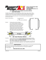
9. INSTALLATION OF CONTROLS
20
10. INSTALLATION OF DISPLAY CABLE HARNESS
20
11. MAIN WIRING HARNESS AND POWER CORD INSTALLATION
20
WIRING INSTALLATION
21
HARVEST TEC 496 TABLE OF CONTENTS

3
12. DESCRIPTION OF BUTTONS
22
13. FIRST TIME AND ANNUAL START UP INSTRUCTIONS
23
CHECKING AND PRIMING THE PUMPS
23
14. SETTING UP THE SYSTEM FOR INITIAL USE
24
APPLICATION RATE
24
BALING RATE
25
OPERATING INSTRUCTIONS
26
AUTOMATIC MODE
26
MANUAL MODE
27
JOB RECORDS
28
DIAGNOSTICS
29
COMMON QUESTIONS ABOUT THE 465
30
MAINTENANCE
31
MAINTENANCE SCHEDULE
31
WINTER STORAGE
31
TROUBLE SHOOTING
32-33
BACKUP FUSE
33
WIRING DIAGRAMS
34-35
PARTS BREAKDOWN
36-45
TANK, SADDLE, AND LEGS
36
PUMP PLATE
37
STAR WHEELS AND HOSES
38
CONTROL BOX AND WIRING HARNESSES
39
4438B AND 4439B
40
4490B AND 4491B
41
4492B AND 4494B
42
4495B AND 4497B
43
4498B AND 4499B
44
4500B AND 4501B
45
TEMPLATE
46
NOTES
47
WARRANTY STATEMENT
BACK
PAGE

4
INTRODUCTION
Congratulations on purchasing a Harvest Tec Model 496 applicator. This applicator is designed to
apply Harvest Tec buffered propionic acid. The model 496 base kit includes the following parts:
Tank, Frame, Pumps, Hose, Baler Mounted Processor, Touchscreen Display, Moisture Sensors, and
Miscellaneous Hardware. The applicator can be installed on most large square balers with the
proper installation kit. Before installing the unit on the baler, make sure you have the proper
installation kit. (See the chart below.) If you are unsure about your installation kit contact your
dealership for specifications. For your convenience we have included a parts break down for the
model 496 applicator. If something goes wrong, bring this manual into the dealership so they can
order the correct parts for you. Ordering the correct part number is very important. It will save you
time, money, and your crop.
INSTALLATION KIT REFERENCE CHART
BALER MAKE
MODEL
INSTALL KIT
HESSTON
4750-4755
4760
4790
4900-4910
4760 ROTO-CUTTER
4790 ROTO-CUTTER
030-4490B
030-4494B
030-4492B
030-4491B
030-4500B
030-4501B
CASE IH
8570-8575
8585
8580-8590
LBX331-332 STD OR PACKER
LBX431-432 STD OR PACKER
LBX331-332 ROTO-CUTTER
LBX431-432 ROTO-CUTTER
030-4490B
030-4492B
030-4491B
030-4495B
030-4495B
030-4497B
030-4497B
CHALLENGER
LB33
LB34
LB44
030-4494B
030-4492B
030-4491B
KRONE
VFS 88
VFS 88 CUTTER
VFS 128
VFS 128 CUTTER
030-4498B
030-4495B
030-4498B
030-4495B
CLAAS
2200
030-4499B
NEW IDEA
7233
7234
7244
7333
030-4490B
030-4492B
030-4491B
030030 030-4494B
NEW HOLLAND
590-BB940A STD OR PACKER
595-BB960A STD OR PACKER
BB940-BB940A ROTO-CUTTER
BB960-BB960A ROTO-CUTTER
030-4495B
030-4495B
030-4497B
030-4497B
VERMEER
SQ2731
SQ3347
030-4438B
030-4439B
TOOLS NEEDED FOR
INSTALLATION:
- Standard wrench set
- Electric drill and bits
- Side cutter
- Crescent wrench
- Standard screwdriver
- Standard nut driver set
- Standard socket set
- Hammer
- Metal cutting tools
- Metal drilling tools
- Hose cutter
- Center punch

5
INSTALLATION OF APPLICATOR
1. INSTALLATION OF TANK
New Holland and Case IH LBX series balers
Assemble the legs to the tank saddle. The inner holes on the saddle should be used for mounting the saddle to the tank
legs on 590-BB940A, and LBX 331-332 balers while the outer two holes should be used for the 595-BB960A, and LBX
431-432 balers. The saddle and tank legs bolt together with 3/8” bolts. Then lift the saddle and legs onto the baler to
mark holes for drilling. Mount the tank legs and saddle on the baler as shown below. The tank legs bolt to the baler with
½” carriage bolts (qty 6). Depending on the baler model, 9/16” holes (3 per side) may need to be drilled in the baler to
bolt down the tank legs. The bolts should be inserted from inside the baler.
The saddle is intentionally tipped forward by 5o so that the tank cap will be parallel to the ground. There is a small cut out
“V” where the tank sump fits in the saddle and this cut out should face the back of the baler for the tank to be level when
installed on the baler.
Note: See Step 3 for drain line installation.
Vermeer SQ2731 and SQ3347 balers
Assemble the legs to the tank saddle. Then lift the saddle and legs onto the baler to mark holes for drilling. Mount the
tank legs and saddle on the baler as shown below. The tank legs bolt to the baler with ½” carriage bolts (qty 6). You will
need to drill 9/16” holes (3 per side) in the baler to bolt down the tank legs. The bolts should be inserted from inside the
baler. The inner holes on the saddle should be used for mounting the saddle to the tank legs on Vermeer SQ2731 and
the outside holes should be used for mounting the saddle on the Vermeer SQ3347 balers. The saddle and tank legs bolt
together with 3/8” bolts.
The saddle is intentionally tipped forward by 5o so that the tank cap will be parallel to the ground. There is a small cut out
“V” where the tank sump fits in the saddle and this cut out should face the back of the baler for the tank to be level when
installed on the baler.
Note: See Step 3 for drain line installation.

6
Claas 2100 and 2200 balers
Assemble the legs to the tank saddle. Then lift the saddle and legs onto the baler to mark holes for drilling. Mount the
tank legs and saddle on the baler as shown below. The tank legs bolt to the baler with ½” carriage bolts (qty 6). You will
need to drill 9/16” holes (3 per side) in the baler to bolt down the tank legs. The bolts should be inserted from inside the
baler. The saddle and tank legs bolt together with 3/8” bolts. The leg containing the four 5/16”holes should be placed on
the left side of the baler. Make sure to mount the tank legs as far back as possible to allow room for using the ladder.
The saddle is intentionally tipped forward by 5o so that the tank cap will be parallel to the ground. There is a small cut out
“V” where the tank sump fits in the saddle and this cut out should face the back of the baler for the tank to be level when
installed on the baler.
Note: See Step 3 for drain line installation.
Hesston 4750, 4755, 4760, 4790, 4900, and 4910, Case-IH 8570, 8575, 8585, 8580, and 8590,
Challenger LB33, LB34, and LB44, and New Idea 7233, 7234, 7244,and 7333 balers.
Remove light bar from beam located on back of baler and secure to bale chute chain. With help, lift the tank assembly to
the beam. (Some installs kits include a spacer which needs to be placed in between saddle and cross beam (part #001-
6702S.) Using the “L” bolts provided, slide the long end of the bolt underneath the beam. Rotate the other end of the
bolt up into the slotted holes on the bracket. Put flat washers on the slotted end of “L” bolt. Secure down with a lock
washer and a nut. Repeat Step C for the other three holes. Use the angle irons included in the kit to bolt light bracket to
rear of tank frame. NOTE: you will have to drill new ¼” holes in the light bracket.
Note: See Step 3 for drain fill line installation instructions.

7
Krone VFS 88 and 128 balers
Assemble the legs to the tank saddle. The outside holes on the saddle should be used for mounting the saddle to the
legs for the VFS 128. The inside holes will be used on the VFS 88. The saddle and tank legs bolt together with 3/8”
bolts. The leg containing the four 5/16” holes should be placed on the left side of the baler. Then lift the saddle and legs
onto the baler to mark holes for drilling. Mount the tank legs and saddle on the baler as shown below. The tank legs bolt
to the baler with ½” carriage bolts (qty 6). You will need to drill 9/16” holes (3 per side) in the baler to bolt down the tank
legs. The bolts should be inserted from inside the baler.
The saddle is intentionally tipped forward by 5o so that the tank cap will be parallel to the ground. There is a small cut
out “V” where the tank sump fits in the saddle and this cut out should face the back of the baler for the tank to be level
when installed on the baler.
Note: See Step 3 for drain line installation.

8
2. INSTALLATION OF PUMP PLATE
Hesston, New Idea, Challenger, and Case 8570, 8575, 8580, 8585, 8590 balers:
1. Locate mounting weld nuts on saddle as shown in Figure 1.
2. Connect the pump plate mounting bracket (001-4646C), shown in Figure 2, using two 3/8 x 1 1/2 bolts,
nuts, locks, and flat washers to the saddle.
3. Attach the pump plate holder (001-4646D) to pump plate mounting bracket (001-4647) using four 3/8 x
1 1/2 flange head bolts. Figure 3.
The Baler Mounted Processor and pump heads must be pointing down. Failure to mount the pump
plate assembly in this specified direction will void all warranty of the Baler Mounted Processor and
pumps.
Figure 1
Figure 2
Figure 3

9
Case and New Holland 3 x 3 balers
1. Install both legs on the saddle by loosely attaching four 3/8 x 1 1/4 bolts, flats and lock washers to the
side of the tank that will face the back of the baler and by loosely attaching the two inside 3/8 x 1 1/4
bolts, flats and lock washers (Figure 1) to the side of the tank that will face the front of the baler.
2. Connect the pump plate mounting bracket (001-4646C), shown in Figure 2, on the remaining two
outside holes, using two 3/8 x 1 1/2 bolts, nuts, locks, and flat washers. Tighten all eight 3/8 inch
bolts.
3. Attach the pump plate holder (001-4646D) to pump plate mounting bracket (001-4647) using four 3/8 x
3/4 flange head bolts. Figure 3.
The Baler Mounted Processor and pump heads must be pointing down. Failure to mount the pump
plate assembly in this specified direction will void all warranty of the Baler Mounted Processor and
pumps
Figure 1
Figure 2
Figure 3

10
Case and New Holland 3 x 4 balers
1. Install both legs on the saddle by loosely attaching four 3/8 x 1 1/4 bolts, flats and lock washers to the
side of the tank that will face the back of the baler and by loosely attaching the two outside 3/8 x 1 1/4
bolts, flats and lock washers (Figure 1) to the side of the tank that will face the front of the baler.
2. Connect the pump plate mounting bracket (001-4646C), shown in Figure 2, on the remaining two
inside holes, using two 3/8 x 1 1/2 bolts, nuts, locks, and flat washers. Tighten all eight 3/8 inch bolts.
3. Attach the pump plate holder (001-4646D) to pump plate mounting bracket (001-4647) using four 3/8 x
3/4 flange head bolts. Figure 3.
The Baler Mounted Processor and pump heads must be pointing down. Failure to mount the pump
plate assembly in this specified direction will void all warranty of the Baler Mounted Processor and
pumps.
Figure 1
Figure 2
Figure 3

11
Claas, Vermeer, and Krone 3x3 balers
1. Install both legs on the saddle by loosely attaching four 3/8 x 1 1/4 bolts, flats and lock washers to the
side of the tank that will face the back of the baler and by loosely attaching the two inside 3/8 x 1 1/4
bolts, flats and lock washers (Figure 1) to the side of the tank that will face the front of the baler.
2. Connect the pump plate mounting bracket (001-4646C), shown in Figure 2, on the remaining two
outside holes, using two 3/8 x 1 1/2 bolts, nuts, locks, and flat washers. Tighten all eight 3/8 inch
bolts.
3. Attach the pump plate holder (001-4646D) to pump plate mounting bracket (001-4647) using four 3/8 x
3/4 flange head bolts. Figure 3.
The Baler Mounted Processor and pump heads must be pointing down. Failure to mount the pump
plate assembly in this specified direction will void all warranty of the Baler Mounted Processor and
pumps.
Figure 1
Figure 2
Figure 3

12
Claas, Vermeer, and Krone 3x4 balers
1. Install both legs on the saddle by loosely attaching four 3/8 x 1 1/4 bolts, flats and lock washers to the
side of the tank that will face the back of the baler and by loosely attaching the two outside 3/8 x 1 1/4
bolts, flats and lock washers (Figure 1) to the side of the tank that will face the front of the baler.
2. Connect the pump plate mounting bracket (001-4646C), shown in Figure 2, on the remaining two
inside holes, using two 3/8 x 1 1/2 bolts, nuts, locks, and flat washers. Tighten all eight 3/8 inch bolts.
3. Attach the pump plate holder (001-4646D) to pump plate mounting bracket (001-4647) using four 3/8 x
3/4 flange head bolts. Figure 3.
The Baler Mounted Processor and pump heads must be pointing down. Failure to mount the pump
plate assembly in this specified direction will void all warranty of the Baler Mounted Processor and
pumps.
Figure 1
Figure 2
Figure 3

13
3. INSTALLATION OF THE DRAIN/FILL LINE
A) Thread ¾” elbow fitting into end of tank.
B) Run hose from the elbow down the frame to the bottom of the baler.
C) Drill ¼” holes to accept the valve holder bracket and use 5/16” x11/4” self-tapping screws.
D) Connect valve assembly to other end of hose. Place hose clamps on both ends.
E) Secure hose to frame using cable locks (see picture below.)
4. INSTALLATION OF THE SPRAY SHIELD
The spray shield assembly is designed to spray the hay evenly as the baler picks it up. A sketch of the spray shield
nozzle holder is shown below.
High Output Tips for Rates Requiring 84-632 lbs/hr. (Approximately 21-63 tons/hr)
Low Output Tips for Rates Requiring 44-400 lbs/hr. (Approximately 11-40 tons/hr)
Spray shield showing nozzle placement and tubing.
Blue tips (Part #: 004-TT11003VP)
Green tips (Part #: 004-TT110015VP)
Orange tips (Part #: 004-TT11001VP)
--Blue Hose
--Green Hose
--Clear Hose
Green tips (Part #: 004-TT110015VP)
Orange tips (Part #: 004-TT11001VP)
Brown tips (Part #: 004-800067-PT)
--Blue Hose
--Green Hose
--Clear Hose

14
Installation kit 4438B for Vermeer SQ2731
Spray shield placement for Vermeer SQ2731
Installation kit 4439B for Vermeer SQ3347
Spray shield placement for Vermeer SQ3347
The spray shield is installed on the gathering fork guard located in the back of the pick up head.
Existing bolts are used to fasten the spray shield bracket to the gathering fork guards. Route hoses so
they will not interfere with moving parts. This can be checked by rotating the flywheel by hand. Don’t
fasten hoses to metal hydraulic lines! A parts breakdown is located in the back of the manual.
The spray shield is installed on the gathering fork guard located in the back of the pick up head. Existing bolts
are used to fasten the spray shield bracket to the gathering fork guards. Route hoses so they will not interfere
with moving parts. This can be checked by rotating the flywheel by hand. Don’t fasten hoses to metal
hydraulic lines! A parts breakdown is located in the back of the manual.
Use existing hardware when mounting the
spray shield bracket.

15
Installation kit 4490B for Case IH 8570 and 8575, Hesston 4750 and 4755, and New Idea 7233
balers
The spray shield holder will be installed underneath the baler’s tongue. Bolt the right side up using the existing hole on
the bottom lip of the baler. Use the clamp on the left hand side to tighten the shield against the underside of the tongue.
Tighten the clamp with the two bolts provided. A parts breakdown of the 4490B is located in the back of this manual.
Ref# Description
1. Baler frame / tongue
2. Top part of spray shield assembly mounted to baler
3. Existing bolt in baler used to hold spray shield
4. Pins used to hold two spray shield assemblies together
5. Nozzle holder part of spray shield assembly
6. Hay pick-up attachment
7. Clamping mechanism that holds spray shield to baler frame
8. Bolts (quantity 2) to hold clamp to spray shield
Installation kit 4491B for Hesston 4900 and 4910, Challenger LB44, Case IH 8580 and 8590,
and New Idea 7244 balers
Install the spray shield behind the baler’s cross channel, which is located on the bottom side of the tongue behind the
flywheel. Note the position of the bevel on the spray shield. Clamp the spray shield around the channel using the
backing plates and the ¼” by 7” bolts provided. A parts breakdown of the 4491B install kit is shown in the back of this
manual.
Front View of Spray Shield Assembly
Side View of Spray Shield
1
2
3
4
5
6
7
8
Side View of Spray Shield
Spray shield
Baler cross channel
Baler flywheel
¼” x 7” bolts
Backing plate
Pin to hold assembly
together
Spray shield
Pin to hold assembly
together

16
Installation kit 4492B for Hesston 4790, Case IH 8585, Challenger LB34, and New Idea 7234
balers
Remove the two 3/8” carriage bolts that connect the wrapper extension to the angle support on each side. Place the
brackets 001-4436DL and 001-4436DR in between the angle support and the wrapper extension. Replace the bolts with
3/8” x 1 1/2" carriage bolts, nuts, locks, and flat washers. Before tightening pull down on wrapper extensions so when
tightened the bolts are in the top of the wrapper extension slot.
Installation kit 4494B for Challenger LB33, Hesston 4760, and New Idea 7333 balers
Remove the two 3/8” carriage bolts that connect the wrapper extension to the angle support on each side. Place the
brackets 001-4436DL and 001-4436DR in between the angle support and the wrapper extension. Replace the bolts with
3/8” x 1 1/2" carriage bolts, nuts, locks, and flat washers. Before tightening pull down on wrapper extensions so when
tightened the bolts are in the top of the wrapper extension slot.

17
Installation kit 4495B for New Holland 590 through BB960A, LBX331 through LBX432 balers
and Krone VFS 88 and 128 with cutter
Install the spray shield under the tongue of the baler, behind the flywheel. There are two existing bolt holes 6” to 12”
above the gathering fork guards, connect the spray shield using these holes. The tips should be pointing to the throat of
the baler chamber. A parts breakdown of the 4495B install kit is located in the back of the manual.
Spray shield assemblies for New Holland 590, 595, BB940, BB960, and LBX series and Krone VFS 88 and 128
balers
Ref# Description
1. Baler frame / tongue
2. Top part of spray shield assembly mounted to baler
3. Existing bolts in baler used to hold spray shield
4. Key ring used to hold two spray shield assemblies together
5. Nozzle holder part of spray shield assembly
6. Hay pick-up attachment
Installation kit 4497B for Case LBX331 through LBX432, and New Holland BB940 through
BB960A balers with the roto-cutter option
New Holland BB960A and Case IH LBX 432
The spray shield assembly will be installed underneath the baler’s tongue and behind the baler’s flywheel.
For installation on a BB960A or LBX 432, bolt a mounting bracket extension to each end of the 35” long mounting
bracket using the 5/16” hardware supplied in the kit. Locate the two holes through the bottom flanges of the tongue’s C-
channels behind the flywheel. Position the cross pieces of the mounting bracket so that shorter leg of the bracket’s angle
iron is vertical and the longer leg is pointed toward the baler’s intake throat. Bolt through the two holes on the baler
using the bolts provided. Fasten the mounting bracket through the bottom lip of the tongue frame on each side with the
hardware in the kit. Finally, slide the spray shield studs through the mounting bracket and fasten with the two key rings
provided. A parts breakdown is located in the back of this manual.
Front View of Spray Shield Assembly
Side View of Spray Shield
1
2
3
4
5
6
2

18
New Holland BB940A and Case IH LBX 332
ATTENTION: This install is factory set for a 3x4 baler. To mount this kit on a New Holland BB940A or Case IH LBX
332, you must adjust the nozzle spacing. Failure to adjust nozzle spacing when mounting this kit on a 3x3 baler will
result in improper preservative coverage on your bale.
The mounting bracket extensions are not needed for assembling the unit on a BB940 or LBX 331 baler. Move the three
nozzles on each side to the inside set of three holes. Modify the hose length between the nozzles after adjusting the
nozzle spacing. Finally, follow the BB960 and LBX431 procedure for installing the mounting bracket and spray shield. A
parts breakdown is located in the back of the manual.
Installation Kit 4498B for Krone VFS 88 and VFS 128 baler
Lower the wind guard of the baler to maximize the installation working space. Locate the guards between the hay intake
fingers. Hold the spray shield up so it straddles the top of the guards. Locate the holes on the baler that line up with the
spray shield holders. Connect the spray shield to the baler using 3/8 ” x 1” bolts. Adjust the spray shield so it can be
removed and reinstalled freely once the lynch pins are removed.
Top view of spray shield
Shield
holder
(001-4810A)
Spray shield
(001-4810)
Overlay welded pipe on spray shield to
studs on shield holder
3/8” x 1” bolts

19
Installation kit 4499B for Claas 2200 baler
Installation Kit 4500B for Hesston 4760 Baler with Cutter Option
Locate the sheet metal above the top auger. (Figure 1) Locate the two holes through the sheet metal nearest
the center of the pickup head. Place two 3/8” x 1 1/4" bolts through the sheet metal with the bolt heads on the
bottom side. Place 001-4436CR over the bolts and fasten with 3/8” nuts, locks, and flat washers. Repeat for
001-4436CL on left side of machine. Place spray shield between brackets and tighten hardware.
Install the spray shield-mounting bracket between the two flat vertical plates above the rotor as indicated in the
picture below. Use the existing bolt holes with the hardware from the applicator kit to mount the spray shield
bracket to the baler. Fasten the spray shield onto the spray shield bracket already mounted. Route hoses along
the spray shield bracket towards the right side of the baler, and then back to the tank. When routing the hose
avoid moving parts.
Mount the spray shield bracket between these
two bolts above the rotor.
Figure 1

20
Installation kit 4501B for Hesston 4790 balers with cutter option
4790 cutter balers with top auger. (Figure 1)
Locate the sheet metal above the top auger. Locate the two holes through the sheet metal nearest the center
of the pickup head. Place two 3/8” x 1 1/4" bolts through the sheet metal with the bolt heads on the bottom
side. Place 001-4436CR over the bolts and fasten with 3/8” nuts, locks, and flat washers. Repeat for 001-
4436CL on left side of machine. Place spray shield between brackets and tighten hardware.
4790 cutter balers without top auger. (Figure 2)
Connect spray shield to 001-4436CR and 001-4436CL brackets. Place the assembly across the top of the
pickup head so the spray shield is horizontal. Center the shield over the throat of the baler directly above and
centered over the bottom augers. Mark the holes on both sides and drill two 7/16” holes on each side. Place
two 3/8” x 1 1/4" through the sheet metal bolt heads down. Secure the assembly with 3/8” nut, locks, and flat
washers.
5. PLUMBING
A. Locate the three ¼” hoses colored clear, blue, and green. The pumps will need to be connected to specific tips so
the pump numbers are as follows: Pump 1 is closest to the filter bowl pump 2 is in the middle and pump 3 is the
outside pump.
B. Use warm soapy water when connecting the hose to the pumps located inside the pump plate and install hose
clamps at the same time. Because all nozzles on the spray shield are different, the operator will need to install pump
1 to the orange tips using the clear hose, pump 2 to the green tips using the green hose and pump 3 to the blue tips
using the blue hose.
C. KEEP HOSE AWAY FROM: MOVING PARTS, SHARP METAL, AND HYDRAULIC LINES. WORKING
TEMPERATURE FOR THE HOSE IS 140 oF AND UNDER.
D. Tie the hose down at secure locations on the baler using the enclosed tie straps and cable clamps.
High and Low Output Tips
Your baler comes with two sets of tips: a low set and a high set. The high set comes factory installed.
-The high set will cover outputs of 84 to 632 lbs/hr (Apprx. 21-63 tons/hr) Install the following tips for high output:
Clear hose to orange tips
Green hose to green tips.
Blue hose to blue tips.
-The low set will cover outputs of 44 to 400 lbs/hr (Apprx. 11-40 tons/hr) Install the following tips for low output:
Clear hose brown tips.
Green hose to orange tips.
Blue hose to green tips.
**Refer to Tip Output under APPLICATION RATE of the control unit to calibrate system.
Figure 1
Figure 2
/