Page is loading ...

VISTATM MOVEABLE
LIFEGUARD CHAIR
CORPORATE HEADQUARTERS
WESTERN SALES AND MANUFACTURING PLANT
P.O. Box 400 ● 1017 SW Berg Parkway
Canby, Oregon 97013
(503) 266-2231 ● Fax (503) 266-4334
www.srsmith.com
06-649 ©S.R. SMITH, LLC 2004 SEP 05
ASSEMBLY INSTRUCTIONS

INTRODUCTION
The VistaTM Moveable Guard Chairs are designed for use on commercial pools where
more than one location is desired for one chair. Proper and complete assembly, use, and
maintenance are essential for proper operation and to reduce the risk of accident or
injury.
2
**IMPORTANT**
Check entire box and inside all packing materials for parts. Before beginning assembly, read
the instructions and identify parts using the figures and parts listed in this document. It is
critical that all parts be carefully inspected by the installer prior to installation to ensure that no
damage occurred in transit and that a damaged part is not used. Proper installation cannot
be overstressed, as an improper installation voids S.R. Smith’s warranty and may affect the
safet
y
of the user.
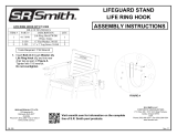
FIGURE 1
20.02
5.00
Ø1.90
(TYP)
51.81
70.50
23.20
57.08
42.00
30.00
50.00
76.54
86.25
11.74
9.66
(TYP)
VISTA 6’
US48500

Ø1.90
5.00
20.02
30.00
42.00
52.44
50.00
10.43
(TYP)
11.74
111.75
3
100.54 95.98 77.31
23.20
63.91
VISTA 8’
US48550
FIGURE 2

VISTA PARTS LIST
ITEM NO. QTY. PART NO. DESCRIPTION
1 1 8-609 LIFEGUARD SEAT
2 1 2407030 SWIVEL, LIFEGUARD CHAIR
3 1 8-612 FOOTBOARD, 30" X 42"
4 2 8-510 GASKET, 7-1/2" X 7-1/2"
5 1 13-117 SWIVEL STAND, W/O UMBRELLA HOLDER
6 1 20-202 SWIVEL STAND MOUNTING PLATE
7 2 FC-100C 10" FULCRUM COVER W/ SLOT
8 1 20-116 UMBRELLA HOLDER ASSEMBLY
9 18 05-14-114 FLAT WASHER, 1/2", SS
10 2 5-117 1/2" X 5-1/2" BOLT, S/S
11 4 5-124 BOLT, 1/2" UNC X 3.0 LG
12 6 05-14-115 LOCK WASHER, 1/2", SS
13 6 05-14-116 1/2" HEX NUT S/S
14 4 05-618 NUT CAP, 1/2", WHITE PLASTIC
15 4 2300300 CARRIAGE BOLT, 3/8" UNC X 4" LONG, SS
16 14 2020049 CARRIAGE BOLT, 3/8" UNC X 2-1/2" LONG, SS
17 6 5-151 LOCK WASHER, 3/8", SPLIT, SS
18 26 5-139 3/8" UNC, HEX NUT, SS, 6FT VISTA
18 30 5-139 3/8" UNC, HEX NUT, SS, 8FT VISTA
19 2 5-149 LOCK WASHER, 1/4", SPLIT, SS
20 2 5-137 HEX NUT, 1/4" UNC, SS
21 1 2024189 SCREW, 1/4" X 3/4" LG, PAN HD, SLOTTED, SS
22 1 20-121 REAR FRAME ASSEMBLY, 6FT VISTA
22 1 20-135 REAR FRAME ASSEMBLY, 8FT VISTA
23 2 20-124 FRONT CROSS TUBE, VISTA
24 2 20-125 BOTTOM RAIL, 6FT VISTA
24 2 20-138 BOTTOM RAIL, 8FT VISTA
25 1 20-122 LEFT FRONT RAIL ASSEMBLY, 6FT VISTA
25 1 20-136 LEFT FRONT RAIL ASSEMBLY, 8FT VISTA
26 1 20-123 RIGHT FRONT RAIL ASSEMBLY, 6FT VISTA
26 1 20-137 RIGHT FRONT RAIL ASSEMBLY, 8FT VISTA
27 4 2350105 TREAD, WHITE, 15 DEGREE, 6FT VISTA
27 6 2350105 TREAD, WHITE, 15 DEGREE, 8FT VISTA
28 8 5-145 FLAT WASHER, 3/8", SS, 6FT VISTA
28 12 5-145 FLAT WASHER, 3/8", SS, 8FT VISTA
29 8 5-167 CRADLE HEAD BOLT, 3/8" X 3-1/4" LG, SS, 6FT VISTA
29 12 5-167 CRADLE HEAD BOLT, 3/8" X 3-1/4" LG, SS, 8FT VISTA
30 2 8-862 PLS 6" WHEEL
31 2 8-104 PLASTIC RAIL END PLUG
32 12 2019060 SPLIT TEE HALF, SS
4

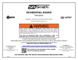
ASSEMBLY INSTRUCTIONS
1. Begin by locating the rear frame, front cross
tubes (2), and the split tees as shown in
FIGURE 3. Attach front cross tubes to the rear
frame by sliding over the inserts as shown in
FIGURE 3. (Do not bolt cross tubes in at this
time) Attach (4) split tee halves at the top of the
rear frame using (4) 3/8”x2-1/2” carriage bolts
and (4) 3/8” hex nuts. NOTE: Do not tighten any
hardware until final step.
Stand rear frame up and attach both front rails
by inserting the top into the split tees already on the
rear frame and the stainless inserts into the front
cross tubes. See FIGURE 4
2. Attach the four 15° white steps using the
supplied pre-packaged hardware. Each
step is fastened using (2) 3/8” Cradle
head bolts, 3/8” flat washers, and 3/8”
hex nuts. See FIGURE 4.
3. Attach footboard to both cross tubes using
(4) 3/8”x4” carriage bolts, ½” flat washers,
3/8” lock washers, and 3/8” hex nuts.
Attach the two bottom rails with (8) split
tee halves, 3/8” x 2-1/2” carriage bolts and
3/8” hex nuts. See FIGURE 5.
5FIGURE 5
323218
22
16
FIGURE 3
23
29
27
18
28
26
25
23
FIGURE 4
15
9
17
18
16
32
32
18
24
3

4. Place Swivel onto Swivel Stand W/O
Umbrella Holder orienting as shown in
FIGURE 6. Place Screw through Swivel
and Swivel Stand (4 places) as shown in
FIGURE 6. Place ¼” Lock Washer and ¼”
Hex Nut onto Screw and tighten (4 places).
5. Attach the seat assembly to the footboard using (4) 1/2"x3” hex head bolts, (8)1/2"
flat washers, (4) 1/2" hex nuts, (4) 1/2" lock washers, (4) 1/2" plastic nut caps and
(1) mounting plate as shown in FIGURE 7. A rubber gasket is placed both above
and below the footboard, in-between the stainless steel plates.
6. Attach the umbrella holder
using (2) 3/8”x2-1/2” carriage
bolts, 1/2" flat washers, 3/8”
lock washers and 3/8” hex
nuts. See FIGURE 8.
Handrail Removed For Clarity
6
1
2
21
19
20
5
20
19
FIGURE 6
14
13
12
9
5
4
11
9
6
4
FIGURE 7
FIGURE 8

7. Install the 6” wheels using (1) 1/2"x5-1/2” hex head bolt, (2) 1/2" flat washers, and
(1) 1/2" lock washer and (1) ½” hex nut as shown in FIGURE 9.
8. Attach the front rubber protective pads and fully tighten all hardware.
See FIGURE 9.
7
SAFETY & MAINTENANCE INSTRUCTIONS
• Do not dive or jump from any part of this guard chair.
• Periodically inspect the VISTA to assure there are no worn
parts and that all hardware is properly tightened.
• All stainless steel parts require periodic maintenance.
Polishing with a cotton cloth and a Windex-type product
maintains the finish and restores luster.
• Use non-abrasive soap and water. Avoid harsh chemicals and
disinfectants. Always read the label instructions on any
cleaner carefully before applying it to a surface.
22
3126 7
10 13129309
FIGURE 9
/