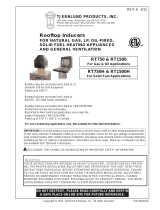
Tjernlund HSJ System Reference Manual

Type
System Reference Manual
Any non-condensing gas or oil fired heater that
can be vented by natural draft can be Side Wall
Vented with a Tjernlund Power Venter. Power
Venters are available in a variety of capacities and
also packaged for specific applications. All models
feature built-in interlock controls and most have
post-purge operation. Selection is based on type
of fuel, burner type and the BTU/hr. input rating
of the heater(s).
Safety proven Side Wall Venting Systems save time
and money and are an excellent choice for electric-
to-gas conversions, renovations, new construction
and for replacing deteriorated chimneys. Side Wall
Venting saves costly materials and labor on two,
three or more story runs. Install heaters where it
was previously impossible...in most cases up to 100
equivalent feet from an outside wall.
Venting for heating appliances
doesn’t have to go through
the roof. Neither does the cost.
www.tjernlund.com
800.255.4208
Tjernlund Side Wall
Venting Products
®
Accessories
A full range of
models from small
residential to large
commercial capaci-
ties. All models
feature the UC1
interlock control,
factory set Fan
Proving Switch and
adjustable damper
to fine tune vent
system draft. Can be used on natural gas, LP and oil-fired
furnaces, boilers and water heaters. We recommend using
the SideShot vent systems for oil fired applications and do
not recommend using the models HS3, 4, 5 for oil due to the
potential volume of soot if the burner goes out of adjust-
ment. Select the appropriately sized VH1-Series Vent Hood
to complete your side wall vent system.
The most technologically
advanced side wall vent
systems available. Now
includes the UC1 Universal
Control. Designed for oil
fired heating equipment
or a deluxe gas vent sys-
tem. Patented terminus
prevents staining by pro-
pelling flue gases away
from the building exterior.
Features: zero clearance installation, pre-wired opera-
tion and safety controls and stainless steel construction
in all critical components. The second generation SS2
features a self-cleaning blower wheel, ultra fine draft
adjustment and slide out venter assembly.
For side wall venting
millivolt gas water
heaters. The ideal solu-
tion for electric-to-gas
conversions, renovations,
new construction or for
replacing old chimneys.
Package includes post-
purge relay/timer, 24V
solenoid valve, gas
pressure switch, spill switch and vent hood. Factory
pre-wired electrical box and 24V control cables
eliminate need for an electrician.
Specially designed to
terminate Tjernlund
Side Wall Vent Systems.
They are also an
approved method of
terminating many hori-
zontally vented appli-
ances. Vent hoods fea-
ture heavy duty, corro-
sive-resistant aluminum
construction. Models VH1-3, 4 and 6 also have built in
clearances from combustibles. Building exteriors are kept
clean while the structure’s exterior aesthetics remain undis-
turbed. All mounting hardware is included.
Solid state control interlocks
with any burner control circuit.
Features include: adjustable pre
and post purge, LED status/
diagnostic indicators, prover
switch delay to avoid burner
start up and wind induced
short cycling. Interlocks with
any 24-120 VAC burner control
circuit and also includes “dry”
contact actuation option.
Selectable voltage eliminates
false activation by burner con-
trol check circuits.
Power Venters
Models HSJ, HS1, HS2, HS3, HS4, HS5
Universal Control
Model UC1
SideShot®Oil and Deluxe Gas
Side Wall Vent Systems
Models SS1, SS1C, SS2
Gas Power Venters and Vent Packages
Models GPAK-JT*, GPAK-1T*, GPAK-1TR*
Primarily used for 80+
gas furnaces and boilers.
Complete kit includes
the Power Venter, VH1-4
4" Vent Hood and DC4
4" Draft Control
packaged together.
Millivolt Gas Water Heater
Venting Packages
Models VP-2, VP-3
Side Wall Power Vent Systems
Vent Hoods
Models VH1-3, VH1-4, VH1-6, VH1-8, VH1-10
1 www.tjernlund.com
800.255.4208
For additional information request brochure #8500004
For additional information request brochure #8500000
Side Wall Venting
Termination
Requirements
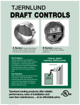
Quality engineered and
manufactured to maintain a
consistent draft on a wide
range of oil and gas fired
heating equipment. May be
used with chimney vented or
power vented heating equip-
ment. For fan assisted gas, oil
or solid fuel applications with
vent diameters from 4"10",
choose the DC4 thru DC10.
For LP and natural gas applica-
tions with vent diameters from 4"10",
choose the DC4G thru DC10G.
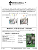
Used with any UC1 con-
trolled venter to inter-
lock additional 24/115
VAC heaters. Powered
by and communicates
with the UC1 through a
factory wired whip. For
one additional 24/115
VAC heater add the
MAC1E. To interlock up
to four more additional 24/115 VAC heaters, add the
MAC4E. MAC4Es can be daisy chained together for
greater than 5 heaters. Important: Total combined
BTU/hr. input of all heaters and total equivalent pipe
lengths must be within venters capacity.
For use with UC1
Universal Control,
MAC1E or MAC4E
auxiliary controls.
The WHKE gas pressure
switch actuates the ven-
ter through the A - B
Dry contacts. The
Linear Limit switch
disables the heater in
the event of a venting
malfunction. Includes JA1 thermocouple junction
adapter. To interlock millivolt water heater(s) only
with a UC1 controlled venter add a WHKE for each
millivolt heater. To interlock a millivolt water
heater and one 24/115 VAC furnace or boiler with a
UC1 controlled venter, add a WHKE and a MAC1E.
Millivolt Interlock Kit
Model WHKE
Barometric Draft Controls
Models DC4, DC5, DC6, DC7, DC8, DC9, DC10
DC4G, DC6G, DC7G, DC8G, DC9G, DC10G
Multiple Appliance Controls
Models MAC1E, MAC4E
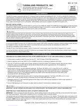
Vent Hood Termination Code Requirements for
U.S. Installations
If possible, locate the Vent Hood on a wall that does not
face the direction of prevailing winds. This will diminish the
possibility of appliance interruption during periods of extreme
winds and prevent oil odors caused by backdrafts.
If possible, locate the Vent Hood no closer than 3
feet from an inside corner of an L-shaped structure.
Terminate the vent system so that proper
minimum clearances are maintained as cited
in the latest edition of the National Fuel Gas Code
(NFPA #54) and the latest edition of NFPA #211,
or as follows:
Not less than 7 feet above grade when located
adjacent to public walkways...
At least 3 feet above any forced air inlet located
within 10 feet...
At least 4 feet below, 4 feet horizontally from or
1 foot above any door, window or gravity air inlet
into any building...
At least 12 inches above grade...
So that the flue gases are not directed so as to
jeopardize people, overheat combustible
structures or enter buildings, and...
Not less than 2 feet from an adjacent building.
NOTE: Termination of a Side Wall Vent System with a device
other than the Tjernlund VH1 Series Hood could affect
system performance and result in a possible safety hazard.
Consult Vent Hood Instructions for complete installation
details.
Accessories
www.tjernlund.com
800.255.4208 2
For additional information request brochure #8500490
Model
Numbers
HSJ
HS1
HS2
Vent
Pipe
Dia.
4"
4"
6"
6"
8"
BTU/hr
Input
50,000
75,000
100,000
125,000
150,000
200,000
250,000
300,000
150,000
200,000
250,000
300,000
350,000
400,000
450,000
500,000
550,000
600,000
350,000
400,000
450,000
500,000
550,000
600,000
100'
100'
100'
35'
100'
87'
40'
4'
100'
100'
100'
30'
100'
100'
100'
100'
94'
15'
100'
100'
100'
100'
100'
67'
100'
100'
100'
23'
60'
57'
12'
100'
100'
92'
100'
100'
100'
72'
100'
100'
100'
100'
100'
100'
35'
27'
100'
100'
100'
100'
67'
100'
100'
100'
0"
SP
110
158
286
.50"
SP
85
115
235
.75"
SP
67
95
215
1.0"
SP
10
12
196
1.4"
SP
158
Maximum Pipe
Length (Ft.)
At Stack Temp.
CFM at 700 F
HS Series (Residential/Light Commercial)
Model
Numbers
HS3
HS4
HS5
Vent
Pipe
Dia.
8"
10"
8"
10"
12"
10"
12"
14"
450,000
500,000
600,000
700,000
450,000
500,000
600,000
700,000
700,000
800,000
900,000
1,000,000
1,100,000
1,200,000
700,000
800,000
900,000
1,000,000
1,100,000
1,200,000
700,000
800,000
900,000
1,000,000
1,100,000
1,200,000
1,200,000
1,400,000
1,600,000
1,825,000
1,200,000
1,400,000
1,600,000
1,825,000
1,200,000
1,400,000
1,600,000
1,825,000
100'
100'
100'
7'
100'
100'
100'
21'
100'
100'
100'
70'
32'
5'
100'
100'
100'
100'
97'
14'
100'
100'
100'
100'
100'
34'
100'
100'
100'
29'
100'
100'
100'
72'
100'
100'
100'
100'
100'
100'
100'
100'
100'
100'
100'
100'
100'
100'
100'
100'
100'
100'
100'
100'
100'
100'
100'
100'
100'
100'
100'
100'
100'
100'
100'
100'
100'
100'
100'
100'
100'
100'
100'
100'
100'
100'
0"
SP
500
925
1425
.50"
SP
425
800
1250
.75"
SP
380
730
1200
1.0"
SP
325
620
1130
1.4"
SP
110
425
1000
CFM at 700F
HS3, 4, 5 Series (Commercial)
Selecting the Proper SideShot®
Vent System
Verify that the total BTU/hr. input of the heating
appliance(s) falls within the proper category listed.
All BTU/hr. capacity ranges are based on a maximum
of 50 equivalent feet. To determine equivalent feet,
add the total length of straight vent pipe plus 10
feet for each 90 degree elbow and 5 feet for each
45 degree elbow. Vent runs of over 15 linear feet
should use an approved insulated vent connector to
prevent problems related to condensation.
Model
SS2
Flame Retention
Oil Burner
70,000
-
168,000*
Max. Equivalent
Feet
50
NOTE: BTU inputs less than 105,000 may require use of
insulated vent pipe for linear runs exceeding 10 feet.
Fan Assisted
Natural & LP Gas Atmospheric
Natural & LP Gas
40,000
-
150,000 BTU/hr 40,000
-
125,000 BTU/hr
*Maximum capacity based on 13% CO2and Max. 5000F inlet temperature. Consult factory for details.
MODEL
SS1
Natural &
LP Gas
50,000 - 160,000
BTU/hr.
Max. Equivalent
Feet
50
Flame Retention
Oil Burner Conventional
Oil Burner
50,000 - 220,000
BTU/hr. 50,000 - 180,000
BTU/hr
MODEL
SS1C
Max. Equivalent
Feet
50
Flame Retention
Oil Burner Conventional
Oil Burner
50,000 - 315,000
BTU/hr. 50,000 - 223,000
BTU/hr
Model Selection Tables
100% Dilution
3000F 25%Dilution
4000F
Maximum Pipe
Length (Ft.)
at Stack Temp.
www.tjernlund.com
800.255.4208 3
1.55 gal/hr. max 1.25 gal/hr. max
2.25 gal/hr. max. 1.59 gal/hr. max. 15.2 meters
1.2 gal/hr. max.
Gas Fired
Selecting the Proper Power Venter
NOTE: The vent pipe diameter in a Power Vent system
is usually smaller than that of a chimney vented
appliance. Select the Power Venter based on the
BTU/hr input of the appliance(s) rather than the
diameter of the appliance vent outlet. Use a tapered
reducing collar or transition fitting to reduce vent
pipe to diameter listed in selection table. To deter-
mine equivalent feet, add the total length of straight
vent pipe plus 10 feet for each 90 degree elbow and
5 feet for each 45 degree elbow.
GAS FIRED
Atmospheric
with Draft
Hood or Draft
Diverter
GAS FIRED
Power
Burner with
Barometric
Oil
Fired
5000F
BTU/hr
Input
3000 F 4000F
NOTE: For capacities over 1,825,000 BTU/hr., consult factory.
Model
VH1–3
VH1–4
VH1–6
A Dia.
3"
4"
6"
B
6 1/4" Sq.
7 1/2" Sq.
8 1/2" Dia.
C
8 1/2"
7 1/8"
7 7/8"
D
10"
13"
12"
E
10"
8 5/8"
9 1/2"
F
5 1/4"
7 3/8"
10 1/2"
G
7 3/4"
11"
10"
Rough-In
Dimensions
6 3/4" Sq.
8" Sq.
9" Dia.
Dimensions
Model
VH18
VH110
A Dia.
8"
10"
B
16"
16"
C
7 3/4"
7 3/4"
D
18 3/8"
18 3/8"
E
20"
20"
Rough-In
Dimensions
8 1/2" Dia.
10 1/2" Dia.
Dimensions
NOTES:
1. If the appliance flue outlet is greater than 4'', install a tapered reducer after the draft
hood, draft diverter or barometric draft control, reducing vent pipe diameter to 4''. All
vent pipe from the appliance to the Power Venter may be 4''.
2.Table is based on straight vent pipe.90 degree elbows are equivalent to 6 feet of
straight vent pipe.
3.Determine maximum pipe length from type of equipment being vented and GPAK Model.
Column A pipe runs over 30 linear feet should use Type “B” vent. Column
B & C pipe runs over 15 linear feet should use Type “B” vent.
4. Column C allows for up to a 40,000 BTU/hr. input atmospheric water heater
common vented with a fan assisted appliance from column B.
5. All reducers and vent pipe are to be supplied by the installer and are available from your
local heating wholesaler.
6. GPAK* Series include a DC-4 Draft Control and VH1-4 Vent Hood and are authorized for
use on furnaces eligible for the HTPV Corrective Action Program. Installations for the
HTPV Program must use Type Bvent.
7. Also available, GPAK-1TR* for use with Rheem, Ruud,Weatherking and Heat Controller brands.
100'
100'
100'
45'
100'
100'
100'
87'
40'
60'
60'
60'
60'
60'
60'
60'
N/A
N/A
60'
60'
N/A
N/A
60'
60'
60'
N/A
N/A
Maximum Total Vent Pipe Length
Models
GPAK-JT*
GPAK-1T*
Vent Pipe
Diameter
4''
4''
45,000
75,000
100,000
120,000
100,000
120,000
150,000
200,000
250,000
*40,000 ATM
Atmospheric Fan Assisted +Column B
A B C
GPAK* Series Selection Table
Unit Dimensions (In.)
Model
VP-2
VP-3
(H)
Height
10 1/2"
7 7/8"
(W)
Width
7 1/2"
10 1/4"
(D)
Depth
10"
7"
Inlet/
Outlet
3"
4"
VP Series Dimensions
Unit Dimensions (In.)
Model
HSJ
GPAKJT*
HS1
GPAK1T*
HS2
(H) Height
7 7/8"
7 7/8"
9 1/4"
(W) Width
10 1/4"
11"
11 1/2"
(D) Depth
7"
7"
8 1/2"
Inlet/Outlet
4"
4"
6"
Unit Dimensions (In.)
Model
HS3
HS4
HS5
(H) Height
12 1/2"
14 3/4"
18"
(W) Width
13 1/4"
15 1/4"
16 1/2"
(D) Depth
11"
13"
16 1/2"
Inlet/Outlet
8"
8"
10"
HS/GPAK Series Dimensions
Model Selection Tables
Model Dimensions
4 www.tjernlund.com •
800.255.4208
VP-2 includes VH1-3 Vent Hood.
VP-3 includes VH1-4 Vent Hood.
VH1 Series Vent Hood Dimensions
VP Series Millivolt Water
Heater Vent Packages Models
VP-2
VP-3
Burner Capacity
Up to 60,000 BTU/hr
60,000 to 120,000 BTU/hr
Maximum Venting Length
75 equivalent feet
75 equivalent feet
BTU/hr
Input
UC1 Universal Control is 8" x 5" x 2 3/4" and includes a 2' wire whip.
SIDE VIEW FRONT VIEW
Vent Pipe Diameter
3"
4"
NOTE: The SS1 features a bottom or rear vent connection. The
inlet collar accepts any brand or type of 6" diameter vent pipe.
The SS1 requires an 8"H x 8 3/8"W opening through the wall.
A B C DE
27-3/8'' 16-1/2'' 12-1/4'' 8'' 13-3/4'' 15-1/8'' 7-3/4'' 14-3/4'' 23-1/4''
F G H I
FRONT VIEW SIDE VIEW
A B C DE
32-1/2'' 28-1/2'' 5-1/2'' 22-3/8'' 7-3/4'' 8'' 12-1/2'' 13-1/4'' 10-1/2'' 8-1/2
F G H I
NOTE: SS2 has a 4" vent connector. Install full size vent pipe and
reduce at SS2 connector. The SS2 requires an 8 1/2"H x 10 1/2"W
opening through the wall.
J
FRONT VIEW SIDE VIEW BACK VIEW
SideShot®Model SS2 Dimensions
TJERNLUND PRODUCTS, INC.
1601 Ninth Street White Bear Lake, MN 55110-6794
Phone: 651.426.2993 800.255.4208 Fax: 651.426.9547
Visit our web site: www.tjernlund.com
Copyright © 2005 Tjernlund Products, Inc. P/N 8500594 Rev C 8/05
Model Dimensions
Voltage
115/1/60
115/1/60
115/1/60
115/1/60
115/1/60
115/1/60
115/1/60
115/1/60
115/1/60
208/1/60
230/1/60
1.76
1.26
1.76
1.26
1.26
2.0
3.2
6.3
13.1
6.2
6.3
Model
HSJ
GPAK-JT*
HS1
GPAK-1T*
GPAK-1TR*
HS2
HS3
HS4
HS5
Model Electrical Specifications
SideShot®Models SS1 & SS1C Dimensions
Tjernlund Products also offers:
Auto-Draft variable & fixed speed inducers. For roof top or side
wall venting. Reduce vent diameters by up to 50% and overcome
convoluted vent layouts. Fan speed is automatically regulated
based on a user set manifold/vent pressure, resulting in perfect
draft and true energy savings. Virtually unlimited capacities.
Combustion Air In-Forcers provide dedicated combustion air
for safer, more efficient equipment operation. Eliminates burner
control lockouts & oil odors associated with backdrafting. Ideal
for "confined space" and electric to oil or gas conversions.
Residential and commercial fixed & variable speed capacities up
to 6000 CFM available.
Auto-Draft®
Inducer
Combustion Air
In-Forcer
5
15*
3
15*
3
3
15*
15*
15*
15*
15****
15****
Voltage
115/1/60
115/1/60
115/1/60
115/1/60
115/1/60
115/1/60
115/1/60
115/1/60
5VDC
2.8
2.8
2.3
1.35
1.76
0.50
0.05***
0.15***
N/A
Model
SS1
SS1C
SS2
VP-2
VP-3
UC1
MAC1E
MAC4E
WHKE
15*
15*
15*
N/A**
N/A**
15*
15*
15*
N/A
Power
Requirements
in Amps
Safety Circuit
Max. Load
in Amps
Power
Requirements
in Amps
Safety Circuit
Max. Load
in Amps
* UC1, MAC1E,MAC4E appliance interlock relay contacts rated for 15 amps or 1 HP.
** Self-contained safety circuit does not interlock directly with gas valve.
*** Power for MAC1E and MAC4E comes from UC1.Add amps listed to that of UC1.
**** UC1 must be wired with 115 VAC. Add UC1 amp draw of .5 to total amps listed.
If wiring the HS5 motor for 208-230 VAC in conjunction with the UC1 Universal
Control, a 115 VAC coil, DPST motor contactor rated for 1 HP is required.
All products are Listed to various
National and International
Codes.
Consult the factory or visit our
web site at: www.tjernlund.com
under the instructions download
button to view instruction manu-
als. Listings are on the cover of
each manual.
  • Page 1 1
  • Page 2 2
  • Page 3 3
  • Page 4 4
  • Page 5 5
  • Page 6 6

Tjernlund HSJ System Reference Manual

Type
System Reference Manual

Ask a question and I''ll find the answer in the document

Finding information in a document is now easier with AI