Page is loading ...

MAC1E OPERATION
The MAC1E is used in conjunction with the UC1 Universal Control to interlock one additional 24 VAC, 115 VAC or millivolt (Dry Contact) con-
trolled appliance. It activates the Venter through its connections to the UC1, and in turn relies on the UC1 Fan Prover safety circuit (P1 & P2) to
allow its interlocked appliance to operate. Any pre/post-purge settings on the UC1 will be defaulted to the MAC1E. Three LEDs are provided on
the MAC1E. LED #1 (Amber) shows an appliance call for heat. LED #2 (Blue) shows that the burner is approved to fire after the Venter Fan
Prover safety circuit through the UC1 is completed. LED #6 (RED) means power is supplied to the MAC1E through the UC1.
MILLIVOLT INSTALLATIONS
Each millivolt appliance interlocked with the MAC1E must have its own WHKE kit installed. The WHKE Gas Pressure Switch actuates the Venter
through the A - B Dry contacts. The Linear Limit switch disables the heater in the event of a venting malfunction. IMPORTANT: Each millivolt
appliance interlocked with the MAC1E must have its own Linear Limit spill switch.
MAC1E MOUNTING
Do not mount the MAC1E junction box on a heat source that exceeds 104oF (40oC). Examples of improper mounting surfaces include vent pipe,
top of appliance casing or any place where radiant or convective heat would cause the junction box temperature to exceed 104oF.
The MAC1E is intended for indoor installation only.
The MAC1E has a 2 foot whip that contains 1 ground, 2 power and 3 communication leads. Mount MAC1E adjacent to UC1 control.
Use the key hole slots on the back of the MAC1E junction box as a template. Mark 4 holes on the mounting surface, drill pilot holes if necessary,
and secure junction box using provided screws.
MAC1E SAFETY INTERLOCK TEST
PERFORM THE FOLLOWING INTERLOCK TEST AFTER CONNECTING MAC1E TO UC1 AND INTERLOCKING ALL BURNERS
1. Confirm power is supplied to MAC1E control from the UC1. MAC1E Power LED #6 (RED) should be on.
2. Initiate an appliance call for heat. MAC1E LED #1 (AMBER) should be on indicating an appliance call for heat.
3. If the UC1, P1 & P2 Prover safety circuit is closed, indicating an approved condition, the appliance interlock relay will close making
terminal #3 closed to terminal #4. MAC1E LED #2 (BLUE) shows that the burner is approved to fire. Fire all appliances
to make sure each burner fires properly.
4. Remove power to the UC1 and any interlocked appliances. The Power LED (RED) on UC1 or any LED’s on UC1 or MAC1E
should not be on. Test the safety circuit by removing either lead from Fan Prover switch connected to UC1 P1 and P2 Fan Prover
safety circuit. Do not let the opened LEAD touch a ground or damage may occur to the control when power is reestablished.
Reestablish power to the UC1 and interlocked appliances and initiate a call for heat. After 60 seconds a Prover Start Up fault
should arise with UC1 LED #4 flashing 3 times.
5. Remove appliance call for heat and power to the UC1 and any interlocked appliances. The Power LED (RED) on UC1 or any
LED’s on UC1 or MAC1E should not be on. Reconnect Fan Prover switch lead removed in step 4.
6. Reestablish power to UC1 and interlocked appliances and initiate a call for heat from each appliance to confirm proper operation of
UC1, MAC1E and appliances.
7. Perform Draft Adjustment and Combustion air safety check as outlined in Venter/Inducer installation manual.
IMPORTANT: DO NOT OPERATE AN APPLIANCE THAT OPERATES WITH THE PROVER SAFETY CIRCUIT DISCONNECTED!
RESETTING FAULT CODE CREATED BY STEP 4 OF SAFETY INTERLOCK TEST
IMPORTANT: Prior to accessing the fault code memory, note the settings of the UC1 dip switches so that they can be returned to their original
Pre / Post-Purge positions. When power is supplied to the UC1 use caution when moving dip switches.
The last fault code can be retrieved at any time by setting all dip switches 1-8 to the up, or “on” position. The last fault code, or lack there of, will
be indicated by counting the number of times LED 4 flashes. By moving any of the dip switches back to their original position, the fault code will
be cleared. NOTE: The UC1 board must have its 115 VAC power supply present when any of the (1-8) dip switches are moved back to their
original position for the fault code to clear.NS WIT
TJERNLUND PRODUCTS, INC.
1601 Ninth Street • White Bear Lake, MN 55110-6794
PHONE (800) 255-4208 • (651) 426-2993 • FAX (651) 426-9547
Visit our web site • www.tjernlund.com
Copyright © 2006, Tjernlund Products, Inc. All rights reserved. P/N 8504110
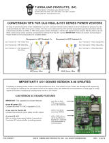
Multiple heaters firing at the same time will result in varying volumes of flue gas and varying vent system draft pressures. Make sure all
heaters interlocked with the MAC1E operate within the normal draft range specified by the heater manufacturer. All heaters utilizing a fixed
speed Venter/Inducer must be equipped with a draft hood, draft diverter, or barometric draft control. Tjernlund ABD-Series Balancing Baffles
may be utilized for balancing draft on each heater.
MAC1E
BOARD
VERSION F
REV. B 11/05

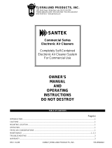
MAC1E WIRING CONNECTIONS WITH UC1 UNIVERSAL CONTROL
Remove power to UC1 and heating equipment when making connections from the MAC1E to the UC1 or installing, servicing or changing dip switch settings in the UC1. Failure to do so may result in
personal injury and/or equipment damage. The Power LED (RED) on UC1 or any LED’s on UC1 or MAC1E should not be on.
See UC1 Universal Control wiring section of Venter or UC1 instructions for 24 VAC, 115 VAC or Millivolt (Dry Contact) appliance interlock diagrams. The MAC1E and UC1 Universal
Control appliance interlock steps and diagrams are identical.MAC1E SAFETY INTERLOCK TEST
L
O
G
R
AE
T
I
V
PROVER
LED1
LED
POWER
RED
24 OR 115 VAC
APPROVED CALL BACK TO HEATER
INTERCEPTED CALL COMMON OR NEUTRAL
24 OR 115 VAC INTERCEPTED CALL FOR HEAT
5 VDC BOARD-GENERATED POWER
DO NOT SUPPLY POWER!
115 VAC
LEGEND:
TERMINAL 2:
TERMINAL 1:
TERMINAL 4:
LED6
VENTER / INDUCER
1 H.P. MAX @ 115 VAC
MOTOR
50/60 Hz
115 VAC
SUPPLY
CEPTED
CALL FOR
HEAT
INTER-
NEUTRAL
LINE / HOT
COMMON /
OR
"DRY"
CALL SWITCH
USER-PROVIDED
APPROVED APPROVED
USER-PROVIDED
CALL SWITCH
"DRY"
OR
COMMON /
LINE / HOT
NEUTRAL
INTER-
HEAT
CALL FOR
CEPTED
MN
LH
TC
EK
IA
B
K2
R
DO NOT SUPPLY VOLTAGE
TO "A" OR "B".
GREEN
RED
RED
CALL
JUMPER
INTERLOCK
XN
XL
NO
J1
J2
COM
K1
RELAY
DRY
IMPORTANT:
115V
24V
LED5 LED3LED4
Y
R
P/N 1303962A
D
E
AMBER
P2
(9)
(3 - 8)
F
89
67
GND
(1 - 2)
14532
C
ON
P1
Burner circuit is energized with contact closure from terminal 3 to terminal 4.
24" FLEX
CONDUIT
MAC1E
Safety circuit through Universal Control P1 & P2 Fan Prover is verified "Open" upon start up.
Appliance call for heat.
LED STATUS INDICATOR LIGHTS
LED #2 (Blue)
installing or servicing the MAC1E. Failure to do so may result in personal
injury and/or equipment damage.
TJERNLUND
PRODUCTS,
INC.
H
T
E
I
W
R
XN
XL
J1
J2
TO "A" OR "B".
DO NOT SUPPLY VOLTAGE
115V
RY
MAC1E CONTROL
L
C
K
A
BD
E
N
G
E
E
R
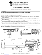
RED JUMPER POSITION MUST BE THE SAME
AMBER
BLUE
CALL
INTERLOCK
RELAY
NO
K1
JUMPER
COM
APPLIANCE "GO"
APPLIANCE CALL
AS APPLIANCE INTERLOCK VOLTAGE.
24V
DRY
IMPORTANT:
LED1LED2
FGND
G
R
A
C
L
O
E
T
I
V
post-purge settings + safety circuit connections are in the Universal Control.
This device must be connected to a Tjernlund Universal Control. All pre and
Remove power to Universal Control and all connected appliances when
NOTE:
WARNING:
LED #1 (Amber)
BLUE
LED2
UNIVERSAL CONTROL
PRE-PURGE SETTINGS
OPEN PROVER OPTION
POST-PURGE SETTINGS
AS APPLIANCE INTERLOCK VOLTAGE.
RED JUMPER POSITION MUST BE THE SAME
N
G
E
E
R
TJERNLUND
INC.
PRODUCTS,
MTR
W
LED
POWER
RED
LED6
Connect Black from MAC1E whip to XL on UC1.
Connect White from MAC1E whip to XN on UC1.
Connect Violet from MAC1E whip to C on UC1
Connect Gray from MAC1E whip to GND on UC1.
Connect Red from MAC1E whip to F on UC1.
Connect Green from MAC1E whip to ground in UC1.
IMPORTANT: Venter Fan Prover must be wired to
P1 and P2 safety circuit in UC1.
RED appliance interlock voltage jumper in MAC1E
and UC1 must be positioned based on the control
voltage of the appliance interlocked with each control
115V, 24V or DRY.
/