
Copyright © 2002, Tjernlund Products, Inc. All rights reserved. P/N 8504111
REV. 9/02
OWNER INSTRUCTIONS, DO NOT DESTROY
Recognize this symbol as an indication of important Safety Information!
NOTE: FLUE GAS TEMPERATURES MUST NOT EXCEED
600oFAT VENT SYSTEM INLET.
THESE INSTRUCTIONS ARE INTENDED AS AN AID TO QUALIFIED, LICENSED
SERVICE PERSONNEL FOR PROPER INSTALLATION, ADJUSTMENT AND
OPERATION OF THIS UNIT. READ THESE INSTRUCTIONS THOROUGHLY
BEFORE ATTEMPTING INSTALLATION OR OPERATION. FAILURE TO FOLLOW
THESE INSTRUCTIONS MAY RESULT IN IMPROPER INSTALLATION, ADJUST-
MENT, SERVICE OR MAINTENANCE POSSIBLY RESULTING IN FIRE, ELECTRI-
CAL SHOCK, CARBON MONOXIDE POISONING, EXPLOSION, PERSONAL
INJURY OR PROPERTY DAMAGE.
!
DO NOT DESTROY. PLEASE READ CAREFULLY AND KEEP
IN A SAFE PLACE ON JOB SITE FOR FUTURE REFERENCE.
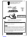
MODELS
HS3
HS4
HS5
FOR NATURAL GAS OR LP
FAN PROVER VENTER
UC1
TJERNLUND PRODUCTS, INC.
1601 Ninth Street • White Bear Lake, MN 55110-6794
PHONE (800) 255-4208 • (651) 426-2993 • FAX (651) 426-9547
Visit our web site • www.tjernlund.com
INCLUDES NEW UC1
UNIVERSAL CONTROL

1
Address all correspondence to:
Customer Service • Tjernlund Products, Inc. • 1601 Ninth Street • White Bear Lake, MN 55110-6794
Call us toll free at 800-255-4208, visit our web site @ www.tjernlund.com or email us at [email protected].
TABLE OF CONTENTS
PAGE(S)
HS3,4,5 DESCRIPTION ............................................................................................................................................... 1
HS3,4,5 SIZING, MODEL SELECTION & SPECIFICATIONS .................................................................................. 1-2
INSTALLATION RESTRICTIONS................................................................................................................................... 3
INSTALLER CAUTIONS ............................................................................................................................................... 3
UC1 UNIVERSAL CONTROL BOARD FEATURES ......................................................................................................4
LED STATUS & FAULT INDICATORS ............................................................................................................................4
PRE / POST-PURGE & PROVER STATUS CHECK SETTINGS...................................................................................5
VENT HOOD LOCATION ............................................................................................................................................. 6
POWER VENTER MOUNTING .................................................................................................................................... 6
VENT PIPE INSTALLATION ..........................................................................................................................................7
UC1 AND FAN PROVING SWITCH INSTALLATION ................................................................................................ 7-8
WIRING ..........................................................................................................................................................................8
WARNINGS, SEQUENCE OF OPERATION & INTERNAL SCHEMATIC ...................................................8-9
WIRING CONNECTIONS FROM UC1 TO FAN PROVER AND MOTOR .......................................................9
MULTIPLE OR MILLIVOLT APPLIANCE INTERLOCKS .................................................................................9
WIRING DIAGRAMS WITH A SINGLE GAS APPLIANCE .......................................................................10-12
UC1 OPERATION CHECK, DRAFT ADJUSTMENT AND COMBUSTION AIR......................................................12-13
MAINTENANCE .......................................................................................................................................................... 14
TROUBLESHOOTING .............................................................................................................................................14-15
WARRANTY & REPLACEMENT PARTS......................................................................................................................15
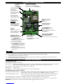
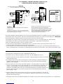
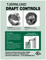
DESCRIPTION
The Tjernlund Power Venter models HS3, HS4 and HS5 are designed to Side Wall or Vertically vent Natural and LP Gas appliances.
After each burner cycle the Venter will continue to operate in post-purge mode to purge the heater and vent of residual flue gases. A
factory post-purge time is set at 2 minutes and is adjustable up 16 minutes, see “Pre / Post-purge Settings” on page 5. The Venter
features a safety system consisting of the integral UC1 Universal Control and a Fan Proving Switch. These devices monitor the
Venter’s performance and will interrupt the main burner if a venting malfunction is detected.
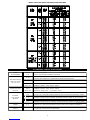
VENTER SPECIFICATIONS
VENTER SIZING
The installer must verify that the Power Venter is sized properly using the selection table on page 2. The installer may reduce the
vent pipe diameter to the size shown in the selection table immediately after the draft hood, draft diverter or barometric draft control.
The vent pipe length shown includes all vent pipe before and after the Power Venter. To calculate the equivalent vent pipe length,
add the straight vent pipe plus 10 feet for every 90 degree elbow and 5 feet for every 45 degree elbow.
If venting multiple appliances with one Power Venter, the total combined BTU/hr. input of all appliances must be added together to
size the Power Venter.
IMPORTANT: Elbows placed directly after discharge on Power Venter may cause erratic operation of Fan Prover. If elbows are
necessary on discharge, allow for a straight section of pipe 3 times the vent diameter being used before installing an elbow.
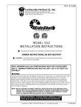
INLET/OUTLET
UNIT DIMENSIONS (IN)
MODEL (H) HEIGHT (W) WIDTH
10"18"HS5 16 1/2"
HS3
HS4 12 1/2"
14 3/4" 8"
8"
13 1/4"
15 1/4"
(D) DEPTH
11"
13"
16 1/2"

2
MODEL
SELECTION
TABLE AND MOTOR SPECIFICATIONS
UC1 UNIVERSAL CONTROL SPECIFICATIONS
POWER
REQUIREMENTS
EXTERNAL
POWER SWITCHING
CAPACITY
J1 / J2
JUMPER
SAFETY
CIRCUIT
ADD VENTER MOTOR
LOAD PLUS 1/2 AMP
FOR UC1 LOAD
EXTERNAL
CALL TRIGGER
METHODS
J1 / J2
P1 / P2
L / N
3 TO 4
T-BLOCK
T-BLOCK
(RELAY K1)
XL / XN
UC1 CONTROL
M & MTR
(RELAY K2)
T-BLOCK
A / B
24V
1 / 2
115V
1 / 2
OR
OR
USED TO JUMP CALL HOT (24 VAC) OR CALL LINE (115 VAC) FROM TERMINAL 1 TO TERMINAL 3.
CONNECTED TO FAN PROVER.
1 mA @ 5 VDC. DO NOT SUPPLY POWER HERE.
REMOVE J1-J2 JUMPER IF A DIFFERENT VOLTAGE SOURCE IS PROVIDED TO TERMINAL 3.
120 VAC ±10 %, 50/60 Hz
MOTOR - 1 H.P. MAX. @ 120 VAC, 50/60 Hz
USER-PROVIDED 24 VAC AT TERMINALS 1 & 2. 1 = CALL HOT, 2 = COMMON. CONTROL
REQUIRES 5 mA @ 24 VAC TO TRIGGER. MOVE RED VOLTAGE JUMPER TO "24V" LOCATION.
3 mA @ 5 VDC. MOVE RED VOLTAGE JUMPER TO "DRY" LOCATION. DO NOT SUPPLY POWER.
USER-PROVIDED CONTACT CLOSURE FROM A TO B. SIZE CONTACT CLOSURE TO HANDLE
GENERAL PURPOSE - 15A @ 120 VAC, 50/60 Hz
DURING OPERATION THE CONTROL USES 50 mA MAX @ 120 VAC
MOTOR - 1 H.P. MAX. @ 120 VAC, 50/60 Hz
150 mA MAX @ 120 VAC, 50/60 Hz
CAN ONLY BE CONNECTED TO TJERNLUND-SPECIFIED AUXILIARY DEVICE
CIRCUIT PROTECTION PROVIDED BY INSTALLER
GENERAL PURPOSE - 15A @ 120 VAC, 50/60 Hz
RESISTIVE - 10A @ 28 VDC PILOT DUTY - 470 VA
USER-PROVIDED 115 VAC AT TERMINALS 1 & 2. 1 = CALL LINE, 2 = NEUTRAL. CONTROL
REQUIRES 1 mA @ 115 VAC TO TRIGGER. MOVE RED VOLTAGE JUMPER TO "115V" LOCATION.
D/N 9183006H

3
INSTALLATION RESTRICTIONS
1. The Power Venter may only be installed on Natural Gas or LP Gas appliances.
2. The Power Venter may not be installed on incinerators, incinerating toilets, condensing-type appliances or solid-fuel burning
appliances.
3. The Power Venter shall not be installed on an appliance with an automatic valve having a manual opener unless the manual
opener has been rendered inoperative or the automatic valve has been replaced with a valve not equipped with a manual opener.
4. The Power Venter may only be installed on an appliance equipped with a draft hood, draft diverter or barometric draft control.
5. The Power Venter shall not be installed where the flue gas temperature exceeds 600oF. at the Power Venter inlet. Flue gas
temperature verification:
A) Consult appliance manufacturer for flue gas temperature after dilution by the draft hood, draft diverter or barometric draft control.
B) Measure flue gas temperature at the Power Venter inlet after installation. Temperature should be measured after appliance and
Power Venter have operated for at least 15 minutes, allowing the flue gas temperature to stabilize.
6. The Power Venter must be mounted so that the shaft of the motor remains horizontal to prevent motor bearing wear.
7. Fan Proving Switch must be mounted with diaphragm in a vertical position. Do not mount the Fan Proving Switch on a heat source
that exceeds 140oF. Examples of improper mounting surfaces include vent pipe, venter, top of heater casing or any place where
radiant or convective heat would exceed 140oF.
8. Ambient temperature surrounding Power Venter must not exceed 104o F.
9. The UC1 is intended for indoor installation only. Do not mount the UC1 junction box on a heat source that exceeds 140oF.
Examples of improper mounting surfaces include vent pipe, top of heater casing or any place where radiant or convective heat
would cause the junction box temperature to exceed 140oF.
4F444444444444444444444 CAUTIONS INSTALLER CAUTIONS
The Power Venter must be installed by a qualified installer in accordance with these instructions and all local codes or in their
absence in accordance with the latest edition of The National Fuel Gas Code (NFPA #54), The latest edition of the National Electrical
Code (NFPA#70) and the Occupational Safety and Health Act (OSHA) when applicable. Improper installation can create a hazardous
condition such as an explosion, fire, electrical shock or carbon monoxide poisoning resulting in property damage, personal injury or
death.
Failure to install, maintain and/or operate the Power Venter in accordance with manufacturer's instructions may result in conditions
which can produce bodily injury and property damage.
Disconnect the power supply from UC1 and heating equipment when making wiring connections or when working around the fan
wheel and motor. Failure to do so can result in electrical shock, personal injury, death or property damage.
1. The Fan Prover must be wired with the appliance so as to prevent the main burner(s) from firing if the Power Venter malfunctions
or the flue is blocked. It is not safe to use the Power Venter as is on millivolt appliances, such as water heaters which employ a
combination gas valve/temperature controller, since the Fan Prover can not be wired as described in this manual. Millivolt appli-
ances require additional interlock controls such as our WHKE kit. See millivolt wiring diagram in this manual for more details.
2. Plan the vent system so that the code required clearances are maintained from plumbing and wiring.
3. To prevent personal injury and equipment damage, disconnect power supply when working on Power Venter.
4. Make certain the power supply is adequate for Power Venter motor requirements. Do not add the Power Venter to a circuit where
the total load is unknown.
5. The installer must verify that the appliance on which the Power Venter will be installed is in a safe operating condition. Consult
appliance manufacturer’s Instructions for details.
6. Plan the vent system layout so that the Power Venter is as close to the point of termination as possible. Vent pipe between the
Power Venter and Vent Hood is acceptable. However, all vent pipe connections after the Power Venter discharge will be under pos-
itive pressure during operation and must be sealed with high-temperature caulk or aluminum vent pipe tape to prevent flue gas leak-
age into the structure.

UC1 UNIVERSAL CONTROL BOARD FEATURES
# 1. Power supplied by board. Do not supply power to this area or control damage may result.
# 2. Do not supply power to the appliance interlock block with the call selector in the “DRY” position.
Control damage may result if power is supplied.
# 3. Circuit protection must be provided by the installer. 16 Amps is the maximum current allowed for this device at terminal L.
A 15 Amp circuit breaker is recommended.VETI
ILED STATUS & FAULT INDICATORS
LED INDICATOR LIGHTS
LED #1 (Amber) Appliance call for heat.
LED #2 (Green) Safety circuit through P1 & P2 (Venter Fan Prover) is verified “Open” upon start-up. Burner circuit is energized
with contact closure from terminal 3 to 4. Also verifies Venter prover is closed during run cycle.
LED #3 (Green) Power switched to Venter motor from L to MTR & M.
LED #4 (Red) Status indicator.
LED #5 (Red) 115 VAC power supplied to board. Also used as status indicator.
LED INDICATOR LIGHT STATUS & FAULTS
LED #4 & #5 Flashing Alternately = Prover start up fault. Venter Prover contacts “Closed” across P1 & P2 upon appliance call
before Venter is turned on. Prover status check must be activated, see page 5.
LED #4 & #5 Flashing in Unison = Fan Prover circuit is “Open” longer than 60 seconds on start-up or 10 seconds during run
cycle. Venter Prover contacts are not staying “Closed” across P1 & P2 safety circuit.
LED #4 Flashing & #5 on Continuous = System in Pre-Purge. (Pre-Purge options 0, 15, 30, 60 seconds)
LED #5 Flashing & #4 on Continuous = System in Post-Purge. (Post-Purge options 0, 30 seconds or 1, 2, 4, 8, 16 minutes)
IMPORTANT: To reset faults, verify fault by checking the LEDs and then remove call for heat.
4
LED STATUS LIGHTS
See “LED Status & Fault
Indicator Section” for details. LED 1 (AMBER)
LED 2 (GREEN)
LED 3 (GREEN)
LED 4 (RED)
LED 5 (RED)
DRY
24 V
115 V
J1- J2 CALL
JUMPER
Used when the call signal is
used as the “proven” return
signal to the appliance. See
wiring section for details.
APPLIANCE INTERLOCK
TERMINAL BLOCK (A-B, 1-4)
A - B - Dry Contact call. 3 mA @ 5VDC.
SEE WARNING # 1.
1- 24 or 115 VAC intercepted call.
IMPORTANT: REDvoltage jumper must
match intercepted call voltage.
2- 24V common or 115V Neutral.
3- Common terminal to appliance relay con-
tacts. IMPORTANT: J1-J2 jumper routes
call voltage at terminal 1 to 3. Remove
J1-J2 jumper if a different voltage source is
provided to terminal 3.
4- Normally open terminal of appliance relay.
Will be energized from terminal 3 if safety
circuit is “proven”.
L / N - 115 VAC POWER
SUPPLY BLOCK
115 VAC / 50-60 Hz
Circuit protection provided by installer.
SEE WARNING # 3.
MTR & M / N LOAD TERMINALS
FROM VENTER MOTOR RELAY
Used to drive Venter Motor.
1 HP MAX LOAD across terminals MTR & M / N.
XL / XN AUXILIARY DEVICE
POWER TERMINALS
115 VAC - Maximum of 0.15 Amps.
Only connect to Tjernlund auxiliary devices.
SEE WARNING #1.
APPLIANCE INTERLOCK
RELAY
1 HP MAX LOAD across
terminals 3 & 4.
VENTER MOTOR RELAY
1 HP MAX LOAD from
terminals L to MTR & M.
APPLIANCE
INTERLOCK
RELAY
VENTER
MOTOR
RELAY
AB 1 2 3 4 L N
J1 J2 XL XN
P1 P2 C GND F
(1 9)
N M MTR
P1 - P2 SAFETY CIRCUIT
TERMINALS
1 mA @ 5VDC.
SEE WARNING # 1.
C, GND, F AUXILIARY DEVICE
COMMUNICATION TERMINALS
2 mA @ 5VDC. For Tjernlund MAC1E or
MAC4E auxiliary devices. SEE WARNING # 1.
APPLIANCE CALL
VOLTAGE SELECTION
Place RED voltage jumper in
proper location based on
appliance call interlock volt-
age. SEE WARNING # 2.
IMPORTANT
DIP SWITCH SETTINGS
Pre-Purge (1-2)
Post-Purge (3-8)
Prover status check (9)
See “Pre / Post Purge &
Prover Status Check Dip
Switch Settings”.

5
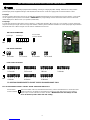
PRE / POST PURGE AND PROVER STATUS CHECK DIP SWITCH SETTINGS
Remove power to UC1 and heating equipment when installing, servicing or changing dip switch settings. Failure to do so may result in
personal injury and/or equipment damage. LED #5 (RED) should not be on if 115 VAC supply power is removed from the control.
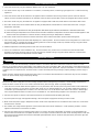
Pre-purge
Used for a Venter with longer vent runs to get draft fully established throughout the vent system prior to burner ignition. Also benefi-
cial for negative pressure prone environments. IMPORTANT: Pre-purge settings must be shorter than flame sensor lockout time
unless wired prior to flame sensor (i.e. aquastat / thermostat).
Post-purge
A Venter post-purge has been factory set at 2 minutes. Confirm that dip switch #5 is in the up or "on" position. A longer post-purge
may be necessary for longer vent runs or high heat retention, refractory lined combustion chambers. A shorter post-purge may be desired
for shorter vent runs or when using the UC1 to control a combustion air In-Forcer.
Pre-Purge Post-Purge Prover Status
Check Activated
DIP SWITCH NUMBERING
1
ON
ON
ON
PRE-PURGE SETTINGS
ON
POST-PURGE SETTINGS
ON
P1 & P2 FAN PROVER SAFETY CIRCUIT “OPEN” UPON APPLIANCE CALL
The Prover Status Check is activated from the factory. When activated the UC1 Universal Control
checks across P1 & P2 safety circuit (Venter Fan Prover) to verify that the Fan Prover switch is
“Open” upon a call for heat and not stuck “Closed”. IMPORTANT: This must always be in the
down “Activated” position when side wall venting.
Prover Status
Check Activated
2 3 4 5 6 7 8 9
9
1 2 1 2 1 2 1 2
0 Seconds 15 Seconds 30 Seconds 60 Seconds
PRE-PURGE SETTINGS
43 4865 7 3 5 6 7 8 3 4 5 6 7 8 3 754 6 8
43 4865 7 3 5 6 7 8 3 4 5 6 7 8
4 Minutes 8 Minutes 16 Minutes
1 Minute0 Seconds 30 Seconds 2 Minutes
P1 & P2 FAN PROVER SAFETY CIRCUIT "OPEN" UPON APPLIANCE CALL

6
VENT HOOD LOCATION
This section only applies if using a Power Venter to Sidewall vent. If using Power Venter to exhaust the flue gases vertically, skip to
the section titled “POWER VENTER MOUNTING” below.
If possible, locate the Vent Hood on a wall that does not face the direction of prevailing winds. This will diminish the possibility of
appliance interruption during periods of extreme winds.
If possible, locate the Vent Hood no closer than 3 feet from an inside corner of an L-shaped structure.
CODE REQUIREMENTS
Terminate the vent system so that proper minimum clearances are maintained as cited in the latest edition of the National Fuel Gas
Code (NFPA # 54) and the latest edition of Chimneys, Fireplaces, Vents, and Solid Fuel Burning Appliances, (NFPA #211), or as follows:
• Not be less than 7 feet above grade when located adjacent to public walk ways.
•At least 3 feet above any forced air inlet located within 10 feet.
•At least 4 feet below, 4 feet horizontally from or 1 foot above any door, window or gravity air inlet into any building.
• At least 1 foot above grade.
• So that the flue gases are not directed so as to jeopardize people, overheat combustible structures or enter buildings, and
• Not less than 2 feet from an adjacent building.
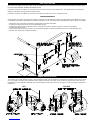
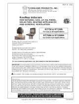
POWER VENTER MOUNTING
The installer must supply plumber’s strap or 1/4” threaded rod with nuts and washers for mounting. The Power Venter may be mount-
ed in any position as long as the shaft of the motor remains horizontal. The Power Venter housing is single wall, 6 inches must be
maintained from all combustible materials. It is recommended that the Power Venter be mounted as close as possible to the point of
termination. HS3 HS4, HS5

7
VENT PIPE INSTALLATION
If Installing the Power Venter on an appliance not equipped with a draft hood or draft diverter (e.g. Power Burners, Induced Draft), a
barometric draft control must be added. The barometric draft control must be the same size as the flue outlet and installed as close
as possible to the appliance. After the draft hood, draft diverter or barometric draft control, a tapered reducer should be installed to
reduce the flue to the size shown in the selection table on page 2 of these instructions. After the tapered reducer, install the appropri
-
ate type of vent pipe to the inlet of the Power Venter. The vent pipe chosen must be in compliance with local codes. The Power
Venter inlet and outlet are designed to accept single wall vent pipe. If using vent pipe other than single wall, the installer must supply
adapters to connect to the Power Venter. While it is recommended that the Power Venter be mounted at the point of termination, it is
acceptable to install vent pipe between the outlet of the Power Venter and the point of termination. The Installer must seal all vent
pipe connections after the Power Venter with high-temperature caulk or aluminum vent pipe tape to prevent flue gas leakage during
operation. The size of the vent pipe between the Power Venter and point of termination should be the same size shown on the selec
-
tion table. Support the vent pipe as recommended by it’s manufacturer. Examples of proper vent pipe installation are shown below.
IMPORTANT:
Elbows placed directly after discharge on Power Venter may cause erratic operation of Fan Prover. If elbows are
necessary on discharge, allow for a straight section of pipe 3 times the vent diameter being used before installing an elbow.
UC1 AND FAN PROVER SWITCH INSTALLATION
Do not mount the UC1 junction box on a heat source that exceeds 140
oF. Examples of improper mounting surfaces include vent
pipe, top of heater casing or any place where radiant or convective heat would cause the junction box temperature to exceed 140
oF.
The UC1 is intended for indoor installation only.
Using the key hole slots on the back of the UC1 junction box as a template, mark 4 holes on the mounting surface, drill pilot holes if
necessary, and secure junction box using provided screws.
The UC1 has a 2 foot whip that contains a ground lead and the leads to power the Venter motor and connect to the Fan Prover. If it
is desirable to mount the UC1 more than 2 feet from the Fan Proving Switch an additional electrical junction box and appropriate
length of conduit will be necessary. Any added wire should be 14 gage and a pig tail should be added to each ground wire connec
-
tion so that each electrical junction box is grounded. See diagram on page 8 for a typical UC1, Fan Prover and Venter installation.

8
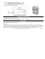
IMPORTANT:
The Fan Proving Switch must be mounted so the diaphragm is in a vertical postion.
1. Mount Fan Prover in a vertical position within 4 feet of the Power Venter so 5 foot sensing tube can be trimmed if necessary. Do
not mount the Fan Proving Switch on a heat source that exceeds 140oF. Examples of improper mounting surfaces include vent
pipe, venter, top of heater casing or any place where radiant or convective heat would exceed 140oF.
2. Connect the 1/4” aluminum tubing from the Fan Proving Switch to the Power Venter housing using supplied fittings. The factory
calibrated sensing tube length and compression fittings are critical for proper operation of the Fan Proving Switch. If it is necessary
to alter the sensing tube length, ONLY trim sensing tube portion that is on the exterior of the housing. IMPORTANT:DO NOT trim
the sensing tube portion that will be mounted in the interior of the housing because Fan Prover will not sense the proper pressure.
Sensing tube assembly with factory calibrated length must be used for Fan Prover to work properly!
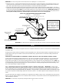
TYPICAL UC1, FAN PROVER AND VENTER INSTALLATION
WIRING
All wiring from the Power Venter to the appliance must be in compliance with the local codes or in their absence, the National Electric
Code (NFPA #70).
All wiring from the Power Venter to the appliance must be appropriate class 1 wiring as follows: Installed in rigid metal conduit, inter-
mediate metal conduit, rigid non-metallic conduit, electrical metallic tubing, Type MI Cable or be otherwise suitably protected from
physical damage.
SEQUENCE OF OPERATION WITH UC1 UNIVERSAL CONTROL AND 24 VAC OR 115 VAC HEATER CONTROL CIRCUIT:
Control signal from thermostat, aquastat, power burner or gas valve is intercepted and routed to terminal “1” on UC1 terminal strip.
When terminal “1” is energized with either 24 VAC or 115 VAC, the Venter motor is energized. After draft is established, the Fan
Proving Switch closes within 5 to 10 seconds energizing terminal “4”, which completes the circuit allowing burner to fire. NOTE: If a
Venter pre-purge is selected, the burner will not fire until the pre-purge time is finished. The Venter will continue to run after the burn-
er has finished firing for the set post-purge time cycle. The UC1 is set for a 2 minute post-purge time period from the factory. See
“Pre / Post-Purge Settings” on page 5 for details.
The "1" input terminal on the UC1 can accept either a 24 VAC or 115 VAC control signal. IMPORTANT: The RED voltage
jumper must be positioned based on appliance interlock voltage. For most furnace applications it may be easier to interlock with the
24 VAC thermostat circuit. For most boiler applications it may be easiest to interlock with the 115 VAC aquastat or burner motor cir-
cuit. Choose the interlock method that best fits your application. If using the “DRY” contact activation method, use terminals A & B on
UC1 control and position the RED voltage jumper tab in the “DRY” position. See millivolt appliance interlock diagram for further infor-
mation.
The steps listed under each diagram are intended as a supplement to the diagram. Wiring colors or designations may vary by manu-
facturer. If you are unable to wire the UC1 as outlined in these instructions, call Tjernlund’s Customer Service Department toll free at
1-800-255-4208 for assistance.
IMPORTANT: To reset faults, verify fault by checking the LEDs and then remove call for heat.
FAN PROVER VENTER
UC1
5 FT. LENGTH PROVIDED
UNLESS ADDITIONAL CONDUIT,
(MINIMUM 14 GAGE)
2 FT. MAXIMUM LENGTH UNLESS ADDITIONAL CONDUIT,
J-BOX AND WIRE ARE ADDED (MINIMUM 14 GAGE)
INSTALLER-SUPPLIED
115 VAC CONNECTION
BURNER INTERLOCK
CONNECTION
INSTALLER-SUPPLIED
2 FT. MAXIMUM LENGTH
ALUMINUM SENSING TUBE
SIDE OF SENSING TUBE
DO NOT ALTER THIS
HOUSING WALL
SENSING TUBE
ASSEMBLY
SENSING TUBE
COMPRESSION RING
BRASS ELBOW FITTING
COMPRESSION RING
J-BOX AND WIRE ARE ADDED
IMPORTANT: As viewed from the opposite end of the shaft (rear of motor), the motor should rotate clockwise.
IMPORTANT:
Do not connect 5 foot section
of aluminum tubing directly to
Venter housing. Sensing
tube assembly provided with
factory calibrated length
must be used or Fan Prover
will not work properly.

9
WIRING CONNECTIONS FROM UC1 UNIVERSAL CONTROL AND MOTOR MADE IN FAN PROVER JUNCTION BOX
The UC1 has a 2 foot whip that contains a ground lead and the leads to power the Venter motor and connect to the Fan Prover. If it
is desirable to mount the UC1 more than 2 feet from the Fan Proving Switch an additional electrical junction box and appropriate
length of conduit will be necessary. Any added wire should be 14 gage and a pig tail should be added to each ground wire connec-
tion so that each electrical junction box is grounded. See diagram on page 8 for a typical UC1, Fan Prover and Venter installation.
WIIRING CONNECTIONS FROM UC1 TO FAN PROVER AND VENTER MOTOR
MODELS HS4 & HS5 (ONLY)
Connect Black and White motor ring terminal leads to ring terminal studs on motor. Connect Ground Lead to ground screw on motor.
IMPORTANT: Motor should be factory wired for proper rotation. As viewed from the opposite end of the shaft (rear of motor), the
motor should rotate clockwise. See motor nameplate for proper rotation.
ALL MODELS (See diagram on page 8 for typical installation)
1. Connect ground wire from UC1 whip and Venter motor ground wire to ground screw in Fan Prover junction box.
2. Connect Black and White motor leads from UC1 whip to Venter motor leads in Fan Prover junction box.
3. Connect Blue and Yellow leads from UC1 whip to Fan Prover switch terminals. Leads are not polarity sensitive.
MULTIPLE APPLIANCE INTERLOCKS
To interlock with one additional 24/115 VAC heater add the MAC1E. It is a stripped down auxiliary board version of the UC1 and is
powered by and communicates with the UC1 through a factory wired whip.
To interlock more than two 24/115 VAC heaters, add the MAC4E for a total of up to 5 heaters. It is powered by and communicates
with the UC1 through a factory wired whip.
To interlock a millivolt water heater and a 24/115 VAC furnace or boiler, add the WHKE and MAC1E.
MILLIVOLT INSTALLATIONS
Each millivolt appliance interlocked with the UC1 must have its own WHKE kit installed. The WHKE Gas Pressure Switch actuates the
Venter through the A - B Dry contacts. The Linear Limit switch disables the heater in the event of a venting malfunction. IMPORTANT:
Each millivolt appliance interlocked with the UC1 must have its own Linear Limit spill switch.
IMPORTANT:
RED JUMPER POSITION MUST BE THE SAME
AS APPLIANCE INTERLOCK VOLTAGE.
CALL
RELAY
INTERLOCK
COMMONNEUTRAL
PRODUCTS,
INC.
MOTOR
1 H.P. MAX @ 115 VAC
SUPPLY
115 VAC
50/60 Hz
R
TJERNLUND
9183006
NO
MTRM
MOTOR
RELAY
N
COM
NO
115 VAC
24 VAC
D/N 1303958-1
DO NOT SUPPLY VOLTAGE
TO "A" OR "B".
DO NOT SUPPLY POWER!
5 VDC BOARD-GENERATED POWER
HOT
24 VAC
USER-PROVIDED
CALL SWITCH
LINE OR
"DRY" OR
115V
J2
COM
24V
DRY
LEGEND:
115 VAC
5
POST-PURGE SETTINGS
FOR TJERNLUND
TO P1, P2, C, GND
AUXILIARY
OR F. DOING SO
WILL DAMAGE THE
CONNECT POWER
OPEN PROVER OPTION
(9)
(3 - 8)
97 86
CONTROL.
DEVICES. DO NOT
FGND
ON
LED1
PRE-PURGE SETTINGS
LED5 LED4 LED2LED3
(1 - 2)
2 431
CP1P2
PROVER
J1
XL
XN
115 OR 24 VAC FROM CALL JUMPER
OR USER-PROVIDED VOLTAGE
FROM TERMINAL 3 TO 4 WITH CALL
JUMPER REMOVED
K2
K1
APPROVED MAC1E OR MAC4E
JUMPER
RED
RED
GREEN
GREEN
AMBER
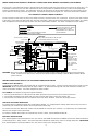
WARNING: Disconnect power supply from the UC1 and heating equipment when making wiring connections and servicing the
Venter. Failure to do so may result in personal injury and/or equipment damage. LED #5 (RED) should be off with
power removed.
UC1 UNIVERSAL CONTROL WIRING SCHEMATIC
The Ground lead, Venter motor and Fan Prover leads are factory connected to the UC1 circuit board. Venter Ground, motor and Fan
Prover wiring connections are made at the free end of the 2 foot whip. Motor should be factory wired for proper rotation. As viewed
from the opposite end of the shaft (rear of motor), the motor should rotate clockwise. See motor nameplate for proper rotation.

10
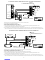
UC1 UNIVERSAL CONTROL CONNECTED WITH A 24 VAC ELECTRONIC IGNITION MODULE
XN
R
UNIVERSAL CONTROLLER
D/N 9183046-8
115 VAC
24 VAC
LEGEND:
HONEYWELL IGNITION
CONTROL
MV
MV
PV
CALL
AS APPLIANCE INTERLOCK VOLTAGE.
RED JUMPER POSITION MUST BE THE SAME
XL
J1J2
DRY
115V
24V
IMPORTANT:
PV
MV / PV (2)
MV (1)
PV (3)
BNR GND (4)
24V GND (5)
24V (6)
(7)
(8)
SPARK (9) OR
PI
YE
GR
YE
WH
OR
YE
WH
OR
GR
GAS VALVE
JUMPER
50/60 Hz
SUPPLY
115 VAC
SPADE TERMINAL IN ELECTRICAL BOX.
GROUND
CRIMP GROUND WIRE TO GROUNDING
IMPORTANT:
1. Remove the wire on MV at gas valve and connect it on #1 on UC1 terminal block.
2. Connect #2 on UC1 terminal block to MV/PV.
3. Connect #4 on UC1 terminal block to MV on gas valve.
4. Make sure RED voltage jumper on UC1 is on 24V.
5. Connect 115 VAC supply voltage to L & N terminals on UC1. Crimp Ground wire to grounding spade terminal in UC1.
Important: Installer must supply overload and disconnect protection.
6. If not completed, connect ground from UC1 whip to Venter ground in Fan Prover j-box. Connect Black & White leads from UC1
whip to Venter motor leads. Connect Blue and Yellow leads from UC1 whip to Fan Prover switch. Prover Leads are not polarity sensitive.
UC1 UNIVERSAL CONTROL CONNECTED WITH A 24 OR 115 VAC STANDING PILOT
115V
24V
DRY
OF FURNACE/BOILER
INTERNAL CONTROLS
24V OR 115V GAS VALVE
HOT
COM
B2
COM
TR
Aquastat
T-stat
TH
HOT
B1
XL
UNIVERSAL CONTROLLER
XN
J1J2
D/N 9183046-1
24 OR 115 VAC
LEGEND:
CALL
JUMPER
115 VAC
50/60 Hz
SUPPLY
115 VAC
SPADE TERMINAL IN ELECTRICAL BOX.
GROUND
CRIMP GROUND WIRE TO GROUNDING
IMPORTANT:
RED JUMPER POSITION MUST BE THE SAME
AS APPLIANCE INTERLOCK VOLTAGE.
IMPORTANT:
1. Remove the wire on TH or HOT of gas valve and connect it on #1 on UC1 terminal block.
2. Connect #2 on UC1 terminal block to TR or Common.
3. Connect #4 on UC1 terminal block to TH or HOT on gas valve.
4. Make sure RED voltage jumper on UC1 is on 24V or 115V depending on control voltage.
5. Connect 115 VAC supply voltage to L & N terminals on UC1. Crimp Ground wire to grounding spade terminal in UC1.
Important: Installer must supply overload and disconnect protection.
6. If not completed, connect ground from UC1 whip to Venter ground in Fan Prover j-box. Connect Black & White leads from UC1
whip to Venter motor leads. Connect Blue and Yellow leads from UC1 whip to Fan Prover switch. Prover Leads are not polarity sensitive.

11
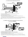
UC1 UNIVERSAL CONTROL CONNECTED WITH AN AQUASTAT
XN
R
UNIVERSAL CONTROLLER
LINE VOLTAGE OIL BURNER
PRIMARY CONTROL, BURNER
L1
N
XL
J1J2
115V
DRY
24V
AQUASTAT
B2
B1
C1
C2
L1
L2
D/N 9183046-7
115 VAC
LEGEND:
CALL
JUMPER
RELAY OR GAS VALVE 50/60 Hz
SUPPLY
115 VAC
RED JUMPER POSITION MUST BE THE SAME
IMPORTANT:
AS APPLIANCE INTERLOCK VOLTAGE.
SPADE TERMINAL IN ELECTRICAL BOX.
GROUND
CRIMP GROUND WIRE TO GROUNDING
IMPORTANT:
CAUTION:
1. Disconnect B1 from L1 of burner relay or hot of gas valve and reconnect to #1 on UC1 terminal block.
2. Connect #2 on UC1 terminal block to B2 or N.
3. Connect #4 on UC1 terminal block to the L1 on line voltage burner relay or gas valve.
4. Make sure RED voltage jumper on UC1 is on 115V.
5. Connect 115 VAC supply voltage to L & N terminals on UC1. Crimp Ground wire to grounding spade terminal in UC1.
Important: Installer must supply overload and disconnect protection.
6. If not completed, connect ground from UC1 whip to Venter ground in Fan Prover j-box. Connect Black & White leads from UC1
whip to Venter motor leads. Connect Blue and Yellow leads from UC1 whip to Fan Prover switch. Prover Leads are not polarity sensitive.
NOTE: If burner control goes out on lockout, the Venter will continue to run as long as a call for heat is present.
UC1 UNIVERSAL CONTROL CONNECTED WITH A SINGLE ZONE 24 VAC THERMOSTAT
XN
R
UNIVERSAL CONTROLLER
THERMOSTAT
GG
INTERNAL CONTROL
OF FURNACE
W
C
Y
R
RY
AS APPLIANCE INTERLOCK VOLTAGE.
RED JUMPER POSITION MUST BE THE SAME
XL
J1J2
W
DRY
115V
24V
IMPORTANT:
D/N 9183046-5
115 VAC
24 VAC
LEGEND:
CALL
JUMPER
50/60 Hz
SUPPLY
115 VAC
SPADE TERMINAL IN ELECTRICAL BOX.
GROUND
CRIMP GROUND WIRE TO GROUNDING
IMPORTANT:
1. Connect W from t-stat to #1 on terminal block of UC1.
2. Connect #2 on UC1 terminal block to C on internal control terminal strip of furnace/boiler.
3. Connect #4 on UC1 terminal block to W on internal control terminal strip of furnace/boiler.
4. Make sure RED voltage jumper on UC1 is on 24V.
5. Connect 115 VAC supply voltage to L & N terminals on UC1. Crimp Ground wire to grounding spade terminal in UC1.
Important: Installer must supply overload and disconnect protection.
6. If not completed, connect ground from UC1 whip to Venter ground in Fan Prover j-box. Connect Black & White leads from UC1
whip to Venter motor leads. Connect Blue and Yellow leads from UC1 whip to Fan Prover switch. Prover Leads are not polarity sensitive.
LINE VOLTAGE BURNER
RELAY OR GAS VALVE

12
UC1 UNIVERSAL CONTROL OPERATIONAL CHECK
1. Confirm power is supplied to the Control. LED #5 (RED) should be on.
2. Activate the UC1 by initiating an appliance call for heat. LED #1 (AMBER) should be on.
3. The motor relay will close and activate the Venter motor. LED #3 (GREEN) should be on and Venter
motor should be running.
4. If the safety circuit across P1 & P2 (Venter Prover) is closed, indicating an approved condition, the
appliance interlock relay will close making terminal #3 closed to terminal #4 & LED #2 (GREEN).
Appliance burner should fire.
5. Remove power to the UC1 and any interlocked appliances. The LED #5 (RED) or any LED’s should
not be on. Test the safety circuit by removing the Blue or Yellow lead from Fan Proving switch. Do
not let the opened LEAD touch a ground or damage may occur to the control when power is Re-
established. Reestablish power to the UC1 and interlocked appliances and initiate an appliance call
for heat. After 60 seconds a Prover Start Up fault should arise with LED #4 (RED) and LED #5
(RED) flashing in unison.
6. Remove appliance call for heat and power to the UC1 and any interlocked appliances. The LED #5
(RED) or any LED’s should not be on. Reconnect Blue or Yellow Fan Prover lead to Fan Prover Switch
terminal removed from in step 5.
7. Reestablish power to UC1 and interlocked appliances and initiate a call for heat to confirm proper operation of UC1 and appliance.
ADSAAAAJUSTMENT
UC1 UNIVERSAL CONTROL AND WHKE INTERLOCK KIT
CONNECTED WITH A MILLIVOLT APPLIANCE
XN
R
UNIVERSAL CONTROLLER
D/N 9183046-9
and WHKE Millivolt Interlock Kit
CALL
AS APPLIANCE INTERLOCK VOLTAGE.
RED JUMPER POSITION MUST BE THE SAME
XL
J1J2
DRY
115V
24V
IMPORTANT:
JUMPER
GENERATED
5 VDC
LEGEND:
115 VAC
WHKE GAS
SAFETY CIRCUIT ACROSS P1 & P2 OF UC1 IS NOT UTILIZED
WITH HEATING EQUIPMENT AS SHOWN.
IN THIS APPLICATION. SPILL SWITCH MUST BE INTERLOCKED
MILLIVOLT
PRESSURE
SWITCH
JUNCTION ADAPTER
THERMOCOUPLE
950-0470 (JA1)
LINEAR LIMIT
SPILL SWITCH
GAS
VALVE
30 MILLIVOLT WATER HEATERS REQUIRE USE OF THE
(ECO) OF WATER HEATER. LINEAR LIMIT SPILL SWITCH,
ON 750 MILLIVOLT (POWER PILE) WATER HEATERS WIRE
LINEAR LIMIT SPILL SWITCH IN SERIES WITH HIGH LIMIT
950-0470 THERMOCOUPLE JUNCTION ADAPTER.
950-0470 JUNCTION ADAPTER AND GAS PRESSURE
SWITCH ARE INCLUDED WITH WHKE KIT.
DO NOT
SUPPLY
POWER.
POWER!
BOARD-
50/60 Hz
SUPPLY
115 VAC
ELECTRICAL BOX.
GROUND
CRIMP GROUND WIRE TO GROUNDING SPADE TERMINAL IN
IMPORTANT:
Each millivolt appliance interlocked with the UC1 must have its own WHKE kit installed. The WHKE Gas Pressure Switch actuates the
Venter through the A - B Dry contacts. The Linear Limit switch disables the heater in the event of a venting malfunction. IMPORTANT:
Each millivolt appliance interlocked with the UC1 must have its own Linear Limit spill switch.
1. Wire WHKE Gas Pressure Switch in series with A and B terminal on UC1. Do not supply voltage to A and B terminals.
2. Wire WHKE Linear Limit in series with thermocouple junction adapter or high limit ECO of water heater.
3. Make sure RED voltage jumper on UC1 is in the DRY position.
4. Connect 115 VAC supply voltage to L & N terminals on UC1. Crimp Ground wire to grounding spade terminal in UC1.
Important: Installer must supply overload and disconnect protection.
5. If not completed, connect ground from UC1 whip to Venter ground in Fan Prover j-box. Connect Black & White leads from UC1
whip to Venter motor leads. Connect Blue and Yellow leads from UC1 whip to Fan Prover switch. Prover Leads are not polarity sensitive.
ON

13
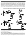
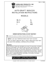
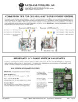
DRAFT ADJUSTMENT AND COMBUSTION AIR
The Power Venter Fan Proving Switch is designed to disable the appliance gas valve or burner motor upon Power Venter failure only!
It is not designed and cannot replace, regular vent system inspection, appliance servicing and combustion testing.
1. Close all doors and windows of the building. If the appliance is installed in a
utility room or closet, close the entrance door to this room.
2. Turn on all exhaust and ventilation fans to maximum speeds. Do not operate a
fan used strictly for Summer exhausting.
3. Following the appliance manufacturer’s instructions, place the appliance in
operation, set thermostat for continuous operation.
4. Verify that Power Venter operates first, prior to burner ignition. Watch to make
sure burner lights off properly.
GAS
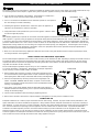
After allowing appliance(s) to operate for 15 minutes, follow the appliance manufacturers instructions to verify that the recommended
draft is present. In general, most gas appliances will operate safely with flue outlet draft levels from -0.02 to -0.05" W.C.. If the draft
is excessive, make necessary adjustments to the barometric control and/or follow the, “Power Venter Air Flow Damper Adjustment”
procedure outlined below. As a cross check, a candle or match can be held adjacent to the draft hood or barometric control to verify
flame/smoke is being drawn into, and not rolling out of edge of the relief opening, (See Diagram A). If exhaust gases are escaping
from the relief opening of the draft hood or barometric control, the equipment should not be operated until proper adjustments or
repairs are made to provide adequate draft levels.
5. Next, turn on all other fuel-burning appliances within the same room so they will operate at their full input. Repeat Step 3 above,
checking the draft on each appliance.
POWER VENTER AIR FLOW DAMPER ADJUSTMENT
The Air Flow Damper Adjustment on the Power Venter is factory set for maximum air flow. Operating a properly sized Power Venter at
its maximum setting will assure that combustion gases are safely removed to the outside. If the Power Venter has excess venting
capacity than what is required for this application, operating the Power Venter with the air-flow adjustment at the maximum setting
may draw more dilution air than necessary.
The Air Flow Damper Adjustment may be set by use of a combustion analyz-
er, inclined manometer or draft gauge. Alternatively, the damper adjustment
can be set using a smoke candle or taper, as follows:
1. With all exhaust fans operating, air inlets closed and all appliances firing
(as instructed above), hold a lighted match or taper around the edge of the
relief opening of the draft hood(s) or barometric draft control, (See Diagram A).
2. Set Air Flow Adjustment by loosening locknut and turning damper rod
handle. CAUTION: HANDLE MAY BE HOT, use pliers to move handle.
Position of rod handle indicates the position of Air Flow Adjustment inside
housing, ( See Diagram B).
3. Using pliers, move handle towards minimum draft setting until spillage is
detected at draft hood relief opening, then re-open Air Flow Adjustment just
enough to eliminate spillage.
4. Lock Air Flow Adjustment at desired setting by tightening locknut.
5. Return doors, windows, exhaust fans, fireplace dampers and appliances to their previous conditions of use.
COMBUSTION AIR
Adequate combustion air is vital for proper combustion and for safe venting. Likewise, for proper Power Venter performance, ade-
quate combustion air must be available to the appliance. Many installers assume adequate combustion air is present, especially in
older buildings. In some cases this is a false assumption, because many older buildings have been made "tight" due to weatheriza-
tion. Size the combustion air opening(s) into the appliance room as outlined local or national codes. Tjernlund’s IN-FORCERTM
Combustion Air Intake Systems provide a convenient interlocked way to provide combustion air to the equipment room. When
installing a Power Venter it is not necessary to supply any more combustion air than normally required when conventional venting.
Common symptoms of inadequate combustion air include: Fan Proving Switch short cycling, odor present at end of burner cycle, out-
side air enters the structure through the Power Venter during appliance off cycle.
PROPER
DRAFT
ESTABLISHED PROPER
DRAFT
ESTABLISHED
DIAGRAM A
DIAGRAM B

MAINTENANCE
1. Oil every six months with 2 drops of S.A.E #20. The oil ports are located at both ends of the motor.
2. The end-user must semiannually inspect the Vent Hood and vent pipe for blockage, corrosion and leaks.
3. A vent system inspection must be performed annually by a qualified service agency. The inspection should include the operation
circuit check, safety interlock test, combustion air test and a visual inspection of the complete vent system for corrosion, blockage
or leaks. Any corrosion, blockage or leaks detected must be repaired or replaced immediately.
TROUBLESHOOTING
The following guide is intended to be used if a problem occurs during the use of the Venter and UC1. It may be necessary to mea-
sure voltage during troubleshooting. Extreme caution must be exercised to prevent injury. If you are unable to determine the
defective part with the use of this guide, call your Tjernlund distributor or Tjernlund Products direct at 1-800-255-4208 for further assistance.
IMPORTANT: To reset faults, verify fault by checking the LEDs and then remove call for heat.
LED STATUS & FAULT INDICATORS
LED INDICATOR LIGHTS
LED #1 (Amber) Appliance call for heat.
LED #2 (Green) Safety circuit through P1 & P2 (Venter Fan Prover) is verified “Open” upon start-up. Burner circuit is energized
with contact closure from terminal 3 to 4. Also verifies Venter prover is closed during run cycle.
LED #3 (Green) Power switched to Venter motor from L to MTR & M.
LED #4 (Red) Status indicator.
LED #5 (Red) 115 VAC power supplied to board. Also used as status indicator.
LED INDICATOR LIGHT STATUS & FAULTS
LED #4 & #5 Flashing Alternately = Prover start up fault. Venter Prover contacts “Closed” across P1 & P2 upon appliance call
before Venter is turned on. Prover status check must be activated, see page 5.
LED #4 & #5 Flashing in Unison = Fan Prover circuit is “Open” longer than 60 seconds on start-up or 10 seconds during run
cycle. Venter Prover contacts are not staying “Closed” across P1 & P2 safety circuit.
LED #4 Flashing & #5 on Continuous = System in Pre-Purge. (Pre-Purge options 0, 15, 30, 60 seconds)
LED #5 Flashing & #4 on Continuous = System in Post-Purge. (Post-Purge options 0, 30 seconds or 1, 2, 4, 8, 16 minutes)
SYMPTOM 1: VENTER OPERATES CONTINUOUSLY
Verify that Venter is not in post-purge mode which could last up to 16 minutes. A factory post-purge has been set for 2 minutes.
LED #4 (Red) will be on continuously and LED #5 will be flashing during post-purge. A Venter pre-purge could also be set for up to 1
minute. LED #4 (Red) will be flashing and LED #5 will be on continuously during a Venter pre-purge. See “Pre / Post-Purge Settings”
on page 5.
Verify that LED #1 (Amber) is not lit.
Yes,LED #1 (Amber) is lit: Check interlock wiring. UC1 control is receiving constant call for heat signal.
LED #1 (Amber) is not lit: Replace UC1 circuit board part number (HS3 & HS4 950-8801) (HS5 950-8804).
SYMPTOM 2: VENTER MOTOR DOES NOT OPERATE
Verify that UC1 control has power, LED #5 (Red) should be lit. Verify that LED# 4 (Red) or LED# 5 (Red) are not flashing. See “LED
Status & Fault Indicators”, above. Make sure RED voltage selection jumper is positioned according to appliance interlock voltage.
No: Check circuit breaker, disconnect switches and wiring. Confirm that motor leads are connected to N & MTR terminals.
Yes, LED #5 (Red) is lit: Verify that the interlocked burner is calling for heat, LED #1 (Amber) should be lit.
No, LED #1 (Amber) is not lit: Verify interlock wiring and that thermostat/aquastat is adjusted to call for heat. Verify that the RED
voltage selection jumper is installed so that it matches the voltage of the interlocked burner.
Yes, LED #1 (Amber) is lit: Verify Prover safety circuit fault does not exist. See, “LED Status & Fault Indicators”, above.
If faults exist check Prover P1 & P2 safety circuit.
If no faults exist, check for 115 VAC across terminals N and MTR.
Voltage present: Confirm Black and White leads from UC1 whip are securely fastened to motor leads in Fan Prover electrical box. If
so, replace Venter motor.
No voltage present: Replace UC1 circuit board part number (HS3 & HS4 950-8801) (HS5 950-8804).
SYMPTOM 3: VENTER OPERATES, BUT BURNER DOES NOT
NOTE: Prover status check must be activated when side wall venting, see page 5. Venter may be in Pre-purge mode for up to 1
minute before burner fires, See “Pre / Post-purge settings”. IMPORTANT: Venter pre-purge time, if selected, must be shorter than
flame sensor lockout time. For any newly established call for heat the UC1 will run for 60 seconds to try to close the fan prover circuit
(P1 to P2). If circuit can not be made after 60 seconds LED's 4 & 5 (Red) will flash in unison, indicating a prover check circuit fault on
UC1 start up. The UC1 will shut down and LED's 4 & 5 (Red) will flash in unison, indicating a prover check circuit fault on UC1 start
up. NOTE: If flame sensor of burner locks out during the 1 minute period the UC1 safety circuit and LED’s 4 & 5 will be reset. If the
fan prover makes on start up, but breaks for more than 10 seconds during the burner cycle, LED's 4 & 5 (Red) will flash in unison
indicating a prover circuit fault. The UC1 will continue to run for 10 minutes to try to make the prover circuit as long as a call for heat
exists. After 10 minutes the UC1 will shut down and LED's 4 & 5 (Red) will flash in unison indicating a prover circuit fault. Remove
the call for heat and then reestablish to reset the UC1 prover safety circuit (P1 to P2) & LED’s.
14

Verify that LED #2 (Green)
is lit.
Yes, LED #2 (Green) is lit: Verify that "call jumper" is connected from J1 to J2 on UC1 circuit board. With call for heat established,
verify that wiring is correct by measuring voltage between terminals 1 & 2 and 2 & 4 of UC1 terminal strip. Voltage should be the
same in both cases, if not rewire per appropriate diagram. NOTE: If using the “Dry Contact” interlock method, make sure that the
RED voltage selection jumper is installed on the dry contact tabs and High Limit has not tripped.
No, LED #2 (Green) is not lit: Remove call for heat and reestablish a call for heat to reset control. Within 1 minute of call for heat,
carefully jump a wire between P1 & P2 on UC1 control. LED #2 (Green) should light.
No, LED #2 (Green) does not light: Replace UC1 circuit board, part number 950-8801.
Yes, LED #2 (Green) lights up: Remove supply power to UC1. Remove Jumper from P1 & P2. The fan proving switch is not closing
or wiring connections are incorrect/broken. Disrupt call for heat. Remove leads from Fan Prover and initiate a call for heat. With
Venter running, verify that Venter performance is sufficient to close Fan Prover contacts by checking for continuity across switch.
No, continuity is not present: Visually inspect system for blockages. Confirm that maximum Venter BTU/hr. input and vent pipe
lengths are not exceeded or elbows are not installed directly on Venter discharge. IMPORTANT: Do not connect 5 foot section of
aluminum tubing directly to Venter housing. Sensing tube assembly provided with factory calibrated length must be used or Fan
Prover will not work properly. If everything checks out okay, replace fan prover.
Yes, continuity present: Recheck wiring.
HOW TO OBTAIN SERVICE ASSISTANCE
1. If the Venter requires adjustment or repair, we suggest that you contact your installer, contractor or service agency.
2. If you require technical information contact Tjernlund Products, Inc. at 1-800-255-4208.
When contacting Tjernlund Products, Inc., please have the following information available:
1. Model of the Venter the UC1 is interlocked with as shown on the label attached to Venter.
2Name and address of installer and any service agency who performed work on Venter.
3. Date of original installation and dates any service work was performed.
4. Details of the problem as you can best describe them.
LIMITED PARTS WARRANTY AND CLAIM PROCEDURE
Tjernlund Products, Inc. warrants the components of the Venter and UC1 for 1 year from date of installation. This warranty covers
defects in material and workmanship. This warranty does not cover normal maintenance, transportation or installation charges for
replacement parts or any other service calls or repairs. This warranty DOES NOT cover the complete Venter if it is operative, except
for the defective part.
1.) Follow troubleshooting guide to determine defective component. If unable to determine faulty component, contact your
Tjernlund distributor or Tjernlund Products Technical Customer Service Department at 1-800-255-4208 for troubleshooting assistance.
2.) After the faulty component is determined, return it to your Tjernlund distributor for replacement. Please include Venter date
code component was taken from. The date code is located on the Electrical Box coverplate. If the date code is older than 1
year, you will need to provide a copy of the original installation receipt to your distributor. Credit or replacement will only be
issued to a Tjernlund distributor after the defective part has been returned prepaid to Tjernlund.
WHAT IS NOT COVERED
Product installed contrary to our installation instructions
Product that has been altered, neglected or misused
Product that has been wired incorrectly
Product that has been damaged by a malfunctioning or mistuned burner
Any freight charges related to the return of the defective part
Any labor charges related to evaluating and replacing the defective part
REPLACEMENT PARTS
15
TJERNLUND LIMITED ONE YEAR WARRANTY
Tjernlund Products, Inc. warrants to the original purchaser of this product that the product will be free from defects due to faulty material or workmanship for a period of (1) year from the date of origi-
nal purchase or delivery to the original purchaser, whichever is earlier. Remedies under this warranty are limited to repairing or replacing, at our option, any product which shall, within the above stat-
ed warranty period, be returned to Tjernlund Products, Inc. at the address listed below, postage prepaid. THERE ARE NO WARRANTIES WHICH EXTEND BEYOND THE DESCRIPTION ON THE
FACE HEREOF, AND TJERNLUND PRODUCTS, INC. EXPRESSLY DISCLAIMS LIABILITY FOR INCIDENTAL OR CONSEQUENTIAL DAMAGES ARISING FROM THE USE OF THIS PRODUCT.
THIS WARRANTY IS IN LIEU OF ALL OTHER EXPRESS WARRANTIES AND NO AGENT IS AUTHORIZED TO ASSUME FOR US ANY LIABILITY ADDITIONAL TO THOSE SET FORTH IN THIS
LIMITED WARRANTY. IMPLIED WARRANTIES ARE LIMITED TO THE STATED DURATION OF THIS LIMITED WARRANTY. Some states do not allow limitation on how long an implied warranty
lasts, so that limitation may not apply to you. In addition, some states do not allow the exclusion or limitation of incidental or consequential damages, so that above limitation or exclusion may not apply
to you. This warranty gives you specific legal rights and you may also have other rights which may vary from State to State. Send all inquiries regarding warranty work to Tjernlund Products, Inc. 1601
9th Street, White Bear Lake, MN 55110-6794. Phone (651) 426-2993 • (800) 255-4208 • Fax (651) 426-9547 • Email: [email protected]
MODEL HS3
MOTOR KIT 950-1022
WHEEL KIT 950-1013
FAN PROVER KIT 950-1032
HOUSING 950-1014
UNIVERSAL CONTROL 950-8801
CIRCUIT BOARD
MODEL HS4
MOTOR KIT* 950-0131
SHAFT EXTENSION 950-0010
WHEEL KIT 950-1013
FAN PROVER KIT 950-1007
HOUSING 950-1008
UNIVERSAL CONTROL 950-8801
CIRCUIT BOARD
*May need shaft extension kit if old
shaft extension can not be removed.
MODEL HS5
MOTOR KIT 950-1017
WHEEL KIT 950-1015
FAN PROVER KIT 950-1007
HOUSING 950-1018
UNIVERSAL CONTROL 950-8804
CIRCUIT BOARD (HS5)
-
 1
1
-
 2
2
-
 3
3
-
 4
4
-
 5
5
-
 6
6
-
 7
7
-
 8
8
-
 9
9
-
 10
10
-
 11
11
-
 12
12
-
 13
13
-
 14
14
-
 15
15
-
 16
16


Tjernlund HS-3 User manual
- Type
- User manual
- This manual is also suitable for
Ask a question and I''ll find the answer in the document
Finding information in a document is now easier with AI
Related papers
-
 Tjernlund MAC1E CONTROL VERSION F (COMPATIBLE WITH UC1 CONTROL) 8504112 REV B 1105 User manual
-
Tjernlund UC1 User manual
-
 Tjernlund DC8 User manual
-
 Tjernlund SS2 SIDESHOT (DISCONTINUED VERSION-PRE UC1 UNIVERSAL CONTROL) 8504063 REV B 1199 Installation Instructions Manual
-
 Tjernlund I Installation guide
-
 Tjernlund SIDESHOT SS2 User manual
-
 Tjernlund RT750H Owner's manual
-
 Tjernlund SS1R SIDESHOT (DISCONTINUED VERSION-PRE UC1 UNIVERSAL CONTROL) 8504046 REV 0595 Installation Instructions Manual
-
 Tjernlund SANTEK AIR CLEANERS 8504022 REV 1 0195 Owner's Manual & Operating Instructions
-
 Tjernlund DH2P Owner's manual


Other documents
-
 Tjernlund Products HSJ User manual
-
 CFM Corporation PVS-1 User manual
-
Yamaha HS4 Owner's manual
-
-
FIELD CONTROLS PVO-300 User manual
-
-
-
-
-

