Side Wall Venting
Termination
Requirements
Quality engineered and
manufactured to maintain a
consistent draft on a wide
range of oil and gas fired
heating equipment. May be
used with chimney vented or
power vented heating equip-
ment. For fan assisted gas, oil
or solid fuel applications with
vent diameters from 4"–10",
choose the DC4 thru DC10.
For LP and natural gas applica-
tions with vent diameters from 4"–10",
choose the DC4G thru DC10G.
Used with any UC1 con-
trolled venter to inter-
lock additional 24/115
VAC heaters. Powered
by and communicates
with the UC1 through a
factory wired whip. For
one additional 24/115
VAC heater add the
MAC1E. To interlock up
to four more additional 24/115 VAC heaters, add the
MAC4E. MAC4E’s can be daisy chained together for
greater than 5 heaters. Important: Total combined
BTU/hr. input of all heaters and total equivalent pipe
lengths must be within venter’s capacity.
For use with UC1
Universal Control,
MAC1E or MAC4E
auxiliary controls.
The WHKE gas pressure
switch actuates the ven-
ter through the A - B
Dry contacts. The
Linear Limit switch
disables the heater in
the event of a venting
malfunction. Includes JA1 thermocouple junction
adapter. To interlock millivolt water heater(s) only
with a UC1 controlled venter add a WHKE for each
millivolt heater. To interlock a millivolt water
heater and one 24/115 VAC furnace or boiler with a
UC1 controlled venter, add a WHKE and a MAC1E.
Millivolt Interlock Kit
Model WHKE
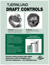
Barometric Draft Controls
Models DC4, DC5, DC6, DC7, DC8, DC9, DC10
DC4G, DC6G, DC7G, DC8G, DC9G, DC10G
Multiple Appliance Controls
Models MAC1E, MAC4E
Vent Hood Termination Code Requirements for
U.S. Installations
If possible, locate the Vent Hood on a wall that does not
face the direction of prevailing winds. This will diminish the
possibility of appliance interruption during periods of extreme
winds and prevent oil odors caused by backdrafts.
If possible, locate the Vent Hood no closer than 3
feet from an inside corner of an L-shaped structure.
Terminate the vent system so that proper
minimum clearances are maintained as cited
in the latest edition of the National Fuel Gas Code
(NFPA #54) and the latest edition of NFPA #211,
or as follows:
•Not less than 7 feet above grade when located
adjacent to public walkways...
•At least 3 feet above any forced air inlet located
within 10 feet...
•At least 4 feet below, 4 feet horizontally from or
1 foot above any door, window or gravity air inlet
into any building...
•At least 12 inches above grade...
•So that the flue gases are not directed so as to
jeopardize people, overheat combustible
structures or enter buildings, and...
•Not less than 2 feet from an adjacent building.
NOTE: Termination of a Side Wall Vent System with a device
other than the Tjernlund VH1 Series Hood could affect
system performance and result in a possible safety hazard.
Consult Vent Hood Instructions for complete installation
details.
Accessories
www.tjernlund.com •
800.255.4208 2
For additional information request brochure #8500490


