Page is loading ...

USER MANUAL ZHS03
WIRELESS DUAL PADDLE
WALL SWITCH
ZHS03
MANUFACTURER INFORMATION
Dear Customer,
should you require technical advice and your
retailer could not help please contact our
technical support.
Schwaiger GmbH
Würzburger Straße 17 90579 Langenzenn
Hotline: +49 (0) 9101 702-199
www.schwaiger.de info@schwaiger.de
BDA_ZHS03_b
Business hours:
Monday to Thursday: 08:00 - 17:00
Friday: 08:00 - 14:30
HOME AUTOMATION
Congratulations and thank you for purchasing the Schwaiger ZHS03 pro-
duct. Below you will find useful operating guidelines.
Product description
Not only can both Z-Wave devices be controlled directly with the Z-Wave.Me wireless wall switch, but
in an IP gateway different scenes can be activated. Although the wireless wall switch controls devices
directly, it cannot as Z-Wave controller manage their networks but always requires an additional con
-
troller for inclusion and exclusion. The device can operate in different modes, which are determined
by configuration parameters:
1. Control groups of other Z-Wave devices with „ON“, „OFF“ and dimming commands.
2. Control of devices in the vicinity of the fob with „ALL ON“ or „ALL OFF“ - commands.
3. Activation of pre-defined scenes in gateways or other Z-Wave devices.
Installation guidelines
The device is delivered in working condition with a built-in battery. In this default condition simply
pressing on one of the buttons - since the device is not included in a network and therefore unable
to send a message - will result in an error code (flashing red LED). In this manner the operational
readiness of the device can be tested.
The device distinguishes between two operating modes: standard and
management mode
Standard mode:
In this mode, the wireless wall switch can control other devices or activate scenes.
Management mode:
The device is switched to management mode when all four buttons are held down together for at least
5 seconds. A slow flashing green LED confirms the management mode. In management mode the
buttons have other functions. Without further button operation, the unit will return to standard mode
in 10 seconds. Each operation also ends the management mode.
In management mode the following actions can be performed:
Button 1
Network-wide inclusion: the device can be added to a Z-Wave network from anywhere in the network.
This requires a primary controller that supports explorer frames. This mode lasts 20 seconds and stops
automatically. Touching any key also stops the mode.
Button 2
Sends node information frame and wake-up messages (as outlined in the following chapters).
Button 3
Standard inclusion/exclusion mode: the device is directed by a controller of direct wireless range.
Touching any button stops the mode. An exclusion of the device from a network resets the device to
its factory defaults.
Button 4
Set associations: to assign target devices to one of the 4 association groups
Batteries
This device is battery-operated. Use only batteries of the specified type.
Used batteries contain hazardous substances and must not be disposed of with household waste!
Battery type: 1 x CR2032
Performance of the device in the Z-Wave network
When delivered the device is not connected to a Z-Wave network. It must be integrated into a Z-Wave
network so that it can communicate with other Z-Wave devices. This process is called Z-Wave inclu
-
sion. Devices can also be removed from networks again. This process is called Z-Wave exclusion.
Both processes are started from a controller that must be connected to an inclusion and/or exclusion
mode. The manual of the controller contains information on how it is to be connected in these modes.
Devices can only be added when the controller of the Z-Wave network is in inclusion mode. Leaving
the network through exclusion will reset this device to its factory defaults.
Bring your Z-Wave controller in the inclusion mode. Bring your wireless wall switch in management
mode and press button 3. The device is included and/or excluded locally by pressing key 3 in man
-
agement mode. In order to include and/or exclude the device network-wide button 1 in management
mode must be pressed.
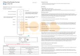
Confirm
network-
wide
inclusion
Confirm
normal inclu-
sion
Node information
frame
Wake-up
Information
Start
association
mode
1 2
3 4
LED
Batterie
Group 1/2
ON
Group 1/2
OFF
Group 3/4
ON
Group 3/4
OFF
1 2
3 4
LED
Batterie
Operation of the device
Depending on the mode and further configuration the device can be set differently.
Standard mode:
Controlling a group with 2 buttons (This is the default setting). One group (no. 1) of the equipment
is controlled with buttons 1 and 3; the other group (no. 2) is controlled with buttons 2 and 4. Buttons 1
and 2 switch the actuators „ON,“ buttons 3 and 4 switch the actuators „OFF.“ If double-click the setting
parameters #1 or #2 is activated, groups 3 and 4 can be controlled by means of short double clicking.
Dimming of devices is enabled through pressing the buttons for a long time (high-dimming with
buttons 1 and 2, low-dimming with buttons 3 and 4) and/or a short click and pressing for groups
with a double click.
A single click controls groups 1 and 3
A double click controls groups 2 and 4
The device can be mounted on every level and dry sur-
face, either with screws or double-sided tape. First the
base plate is secured to the wall. In the next step, the
switching element is secured to the frame. The electron
-
ics module is used to fix the frame to the base plate,
as shown in the figure. Finally, the rocker switches are
mounted on the electronics module.
For a battery change the rocker switches must be re
-
moved. The CR battery can be replaced by pressing the
small locking tab above the battery.
Logging in (inclusion) or logging out
(exclusion) of the sensor.
The device operates in normal control mode or in man-
agement mode. Pushing all four buttons for 5 sec. will
turn the device into management mode (indicated by
blinking green LED). The management mode will time
out after 10 seconds if no further button is pushed.
Button 1 confirms standard inclusion or exclusion
started by a primary controller, button 2 issues a Node
Information Frame or wakeup notification, button 4 is
used to add devices into association groups and button
1 confirms inclusion or exclusion in NWI (network wide
inclusion) mode.

Controls
group 1
Controls
group 3
Controls
group 2
Controls
group 4
1 2
3 4
LED
Batterie
Switches
group 1
Switches
group 3
Switches
group 2
Switches
group 4
1 2
3 4
LED
Batterie
Switches
group 1
Switches
group 3
Switches
group 2
Switches
group 4
1 2
3 4
LED
Batterie
Control commands:
The configuration parameters # 11 to # 14 regulate which commands are sent when the buttons are
pressed.
Direct control of devices occurs through „ON,“ „OFF,“ „HIGH-DIMMING“
and „DOWN-DIMMING.“
The special commands „ALL ON“ and „ALL OFF“ send a group call to all devices in direct wireless range.
The devices react according to their settings to the command „switch everything.“ This mode includes
the communication setting 7.
Simple scene control with configurable scene commands.
Devices in association groups are individually configured with the Z-Wave command class „scene
controller configuration.“ A scene can be configured via an association group. As can be seen in the
figure, the number of the scene is by default equal to the number of association group. This mode is
always used by default to activate scenes in IP gateways, but can also be used to activate predefined
scenes in other devices.
Control commands:
The configuration parameters # 11 to # 14 regulate which commands are sent when the buttons are
pressed.
Direct control of devices occurs through „ON,“ „OFF,“ „HIGH-DIMMING“
and „DOWN-DIMMING.“
The special commands „ALL ON“ and „ALL OFF“ send a group call to all devices in direct wireless range.
The devices react according to their settings to the command „Switch everything.“ This mode includes
the communication setting 7.
Simple scene control with configurable scene commands.
Devices in association groups are individually configured with the Z-Wave command class „Scene
controller configuration.“ A scene can be configured via an association group. As can be seen in the
figure, the number of the scene is by default equal to the number of association group. This mode is
always used by default to activate scenes in IP gateways, but can also be used to activate predefined
scenes in other devices.
Technical specifications
Protection class IP 20
Battery type 1 x CR2032
Z-Wave frequency 868.42 MHz (SRD Band)
Wireless range Up to 100 m outdoors,
Up to 20 m in buildings on average
Explorer Frames Yes
SDK 4.54 pl1
Type of equipment Slave with routing capabilities
General Z-Wave device type Remote switch
Special Z-Wave device type Multi-level remote switch
Router No
FLiRS No
Firmware Version
1.2
Disposal information
This device contains batteries. Please refer to the applicable disposal regulations for batteries. It is an
electrical device. It can be disposed of free of charge at specified disposal sites.
EC Declaration of Conformity
„Hereby Schwaiger GmbH declares that the product ZHS03 is in compliance with the essential require-
ments and other relevant provisions of Directive 1999/5//EC.“ The Declaration of Conformity can be
found at the following address:
http://www.schwaiger.de/downloads
Advanced scene control:
In this mode, pressing any key will trigger a scene command with a set number. The scene number
is a combination of the group number and the defined button press action. It always consists of two
digits. The group number determines the first digit; the action determines the second digit. The fol
-
lowing actions are possible:
1 = on
2 = off
3 = high-dimming start
4 = low-dimming start
5 = high-dimming stop
6 = low-dimming stop
Example: clicking/double-clicking button 1 sends an activation signal for scene 11 (single-clicking)
process and scene 12 (double off, controlling a group with a button is selected). This mode includes
the communication setting 6.
Child protection
The device has a child protection mechanism. Local operation by using buttons is blocked and only
wireless operation is possible. The device can be set to child lock mode. In this mode no local control
is possible. The child lock mode can only be activated wirelessly. Only in protection mode with input
mode it is possible to disable protection by pressing any button for 5 seconds. Only in protection mode
with input mode it is possible to disable protection by pressing any button for 5 seconds. The protec
-
tion is activated again after 5 seconds.
Communication with a battery-powered device
The device is battery-powered and to save power it is thus usually in deep-sleep mode. In deep sleep
mode the device cannot received any wireless signals. Therefore, a static (controller) is required,
which is mains-powered and therefore always available for wireless data transmission. This controller
- for example, an IP gateway - manages a message mailbox for this battery-powered device, in which
messages to the unit can be temporary stored. Without such a static controller using this battery-pow
-
ered device will quickly discharge the battery or render use completely impossible.
This device regularly „wakes up,“ reports this by sending a so-called wake up notification and then
empties its mailbox in the static controller. The node ID of the controller and a wake up interval must
be defined with the inclusion. If the inclusion is carried out by means of a static controller such as an IP
gateway, this controller will automatically perform this configuration and usually offer a user interface,
to adapt the wake up interval to user needs. The wake up interval is a compromise between maximum
battery life and minimum response time of the battery-powered device.
Immediately after the inclusion the device remains awake about 2.5 seconds so that a controller can
perform configuration tasks. The device can then always be woken manually. For this, the manage
-
ment mode is activated (keep all four buttons pressed for 5 seconds) and then press button 2. The
minimum wake up interval is 240 seconds. However, it is highly recommended that you choose a
longer wake up interval to save battery life. If the device ID 0 is selected as the target device for the
wakeup notification, the periodic wake-up is suppressed. It is possible to specify the device number
255 as the destination device for the wake up notification. In this case, the message is sent as a
broadcast to all devices with direct wireless connection. The advantage of immediate notification is
offset by the disadvantage that, where appropriate, the device consumes more time in active mode
and thus more battery capacity.
Meaning of LED signals
1. Confirmation - green 2 seconds
2. Error - red 2 seconds
3. Confirmation of each keystroke - green 1/4 second
4. Waiting for selecting the network mode - green flash
5. Waiting for selection of group in association mode - green flashes quickly
6. Waiting for node information frame in association mode - green-red - without blinking
Controlling a group with a button:
in this mode the groups are controlled by a respective button. Pressing a button switches „ON,“ double
clicking a button switches „OFF.“ High-dimming of devices is achieved by holding the button down
for a long time and low-dimming is achieved by clicking and holding the button. The group number
corresponds to the button number
/