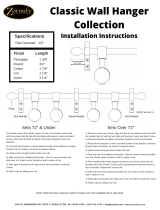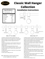
MOUNTING HARDWARE KIT TOOLS REQUIRED
a. Finials
b. Brackets
c. Center Supports
d. Cord Tension Device
e. 1¼ Screws
f. Wall Anchors
INSTALLATION INSTRUCTIONS FOR
DECORATIVE TRAVERSE
INSTALLATION OF BRACKETS AND CENTER SUPPORTS.
Measure carefully, using a steel tape measure. Height: Determine location
where bottom of drapery will be then add 1 ½ inch to drapery length to allow
for the height of the rod and add an additional 1inch (minimum) for oor
clearance for full length drapes. Width: Ready made draperies generally
require 4 inch for return to the wall on each side and 4 inch for center overlap-
thus a total of 12 inch must be subtracted from the actual width of the
drapery panels. The instructions that come with your draperies should inform
you of the actual amount allocated for the return and overlap. For a one way
draw installation there is only one return and no overlap.
Mark bracket location with a pencil, and make sure brackets and center
supports are level. Center supports should be evenly spaced between the
outer brackets. Attach each bracket using the 1 ¼ screws. Use wall anchors
when attaching to hollow drywall. Use a 3/32 inch drill bit for screws and a ¼
inch drill bit for wall anchors.
REMOVE EXTRA RINGS.
Count the number of ring slides needed for your draperies and then remove
the extra ones. One ring is required for each pleat and one for each master
carrier ( 2 masters for Center Draw, 1 master for one way draw). Remove ring
by pressing down on ring stop and slide extra rings out.
ATTACH ROD TO BRACKETS.
Extend the rod as necessary to set it onto the end brackets through the slots
on both ends of the rod making sure there is one ring between the nial and
the bracket on each side or one side for the one way draw. Attach the center
support(s) to the rod as illustrated. The top of the center support bracket rests
on top of the rod. Then loosen the metal clamp so that it engages the ridge on
the back of the rod and then tighten it against the ridge to hold the rod rmly in
place. To adjust bracket if needed, loosen the screw on the bracket slightly, then
ATTACH THE CORD TENSION DEVICE
Cord Tension Device can be attached to a wall, window sill or oor as desired
using 1-1/4” screws (note that the base can be temporarily removed from the
tension device to make attachment easier) Open the head of the device to
expose the pulley wheel- do this by depressing the release lever and pushing
inward on it. (see illustration).
1
2
4 6
CENTER THE MASTER CARRIERS.
After extending the rod it is necessary to re-center the master carriers and
cording system. Slide the master carriers to the opposite ends of the rod as far
as they will go. Make sure there is no slack in the cord, then slip the cord under
the tab on the underlap master carrier as illustrated.
5
HANG THE DRAPERIES
Start at the master carrier on each side. Reverse the rst pin on the
overlap master(attach the hook of the pin from behind the carrier arm- see
illustration)then attach each pleat to a ring arm. The ends of the drapery (not
the pleat) can be pinned to the end bracket on each side of the rod to create
a “return” to the wall. See illustration.
7
Pull the tension device out of the body of the device until the small set wings
come out through the slot – turn the rod so that it is held out of the body. Put
the end loop of the cord onto the pulley wheel and then close the housing.
Grasp the cord behind the overlap master carrier and pull it out to eliminate
the slack between the rod and the tension device-cut off the knot- retie the
cord as close to the master carrier as possible- cut off excess cord. Rotate
the pulley head until the cords are in proper alignment and let the rod retract
into the body to put tension on the cord.
To convert to a one way draw, remove all of the rings behind the underlap
master carrier. Gently tug on the cord until it comes completely out of the
underlap master then slide the master off of the rod. Unscrew and remove the
arm from the underlap master- use it to replace the arm on the overlap master.
The rod can draw either right to left or left to right- turn the arm to face the
correct direction. Arrange all of the rings needed behind the master carrier.
NOTE: The amount of overlap can be adjusted by unscrewing the master carrier
arms and repositioning them. To reverse cord position from the right side to the
left side, simply pull the cord out from the pulley on the left side of the rod. The
master carriers will need to be re-centered as described above.
123
Center support
Center support
Attach finial adapter to finial as shown below. Next, insert one slider and finial
adapter to the end of the rod while pressing (directions shown in arrow) on the
rod. Then tighten the screw on the adapter. Do the same for the other side.”
3


