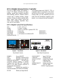
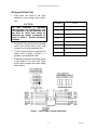
Hygain DCU-3PX is a digital antenna rotator controller with programmable memory, designed for use with HAM-IV and T-2X rotators. It features a large LCD display, manual and computer-controlled beam heading selection, manual rotation controls, and 6 heading memory storage positions. The DCU-3PX also has adjustable brake delay, rotator coast control, North and South center headings, adjustable sleep time, and call sign display. It can be controlled via RS-232 or USB, and comes with a protective fuse and chassis ground for safety.
Hygain DCU-3PX is a digital antenna rotator controller with programmable memory, designed for use with HAM-IV and T-2X rotators. It features a large LCD display, manual and computer-controlled beam heading selection, manual rotation controls, and 6 heading memory storage positions. The DCU-3PX also has adjustable brake delay, rotator coast control, North and South center headings, adjustable sleep time, and call sign display. It can be controlled via RS-232 or USB, and comes with a protective fuse and chassis ground for safety.


-
 1
1
-
 2
2
-
 3
3
-
 4
4
-
 5
5
-
 6
6
-
 7
7
-
 8
8
-
 9
9
-
 10
10
-
 11
11
-
 12
12
-
 13
13
-
 14
14
-
 15
15
-
 16
16
-
 17
17
-
 18
18
-
 19
19
-
 20
20
-
 21
21
-
 22
22
-
 23
23
-
 24
24


Hygain DCU-3PX User manual
- Type
- User manual
- This manual is also suitable for
Hygain DCU-3PX is a digital antenna rotator controller with programmable memory, designed for use with HAM-IV and T-2X rotators. It features a large LCD display, manual and computer-controlled beam heading selection, manual rotation controls, and 6 heading memory storage positions. The DCU-3PX also has adjustable brake delay, rotator coast control, North and South center headings, adjustable sleep time, and call sign display. It can be controlled via RS-232 or USB, and comes with a protective fuse and chassis ground for safety.
Ask a question and I''ll find the answer in the document
Finding information in a document is now easier with AI
Related papers
Other documents
-
 StarTech.com C9PCF Datasheet
-
StarTech.com C25PCF Datasheet
-
Sanyo ECJ-D100S - 10 Cup MICOM Rice Cooker User manual
-
 CUSHCRAFT AR-303X Owner's manual
-
CSI 7798 I/SITE LAN Installation guide
-
Sony Water Dispenser 2 User manual
-
Wacker Neuson G70 User manual
-
-
-

