Page is loading ...

®
Installation Guide
7798 I/SITE™ LAN
I/SITE LAN
for I/NET® Building Automation Systems
TCON138.—.01/99
vi

We at Control Systems International (CSI) have tried to make the information contained in this manual as accurate and reliable
as possible. Nevertheless, CSI disclaims any warranty of any kind, whether express or implied, as to any matter whatsoever
relating to this manual, including without limitation the merchantability or fitness for any particular purpose.
CSI will, from time to time, revise the product(s) described in this manual and reserves the right to make such changes without
obligation to notify the purchaser. In no event shall CSI be liable for any indirect, special, incidental, or consequential damages
arising out of purchase or use of this manual or the information contained herein.
1994–1996, 1999 by Control Systems International. All rights reserved.
Printed in the United States of America.
Document Number: TCON138–01/99
I/NET, Control Systems International, and the Control Systems International logo are registered trademarks of Control Systems
International.
FrameMaker, Minion, and Adobe Illustrator are trademarks of Adobe Systems Incorporated. Canvas is a trademark of Deneba
Software. All other trademarks mentioned belong to their respective owners.
About this manual:
This book was written and produced using FrameMaker workstation publishing software and the Minion font from Adobe.
Illustrations were created or modified using Canvas and Adobe Illustrator.

7798 I/SITE LAN iii
Contents
FCC Warning ...........................................vi
Overview
............................................ 1
Communication .......................................... 1
Physical Description
.................................... 3
Printed Circuit Board ....................................... 3
Communication .................................................4
Communication Expansion Port ........................................5
Reset .......................................................5
Memory .....................................................5
NOVRAM ..................................................5
Static RAM ..................................................6
EPROM ...................................................6
Battery Backup ..................................................6
Power Supply ...................................................6
ViewCon .............................................. 6
Plastic Enclosure .......................................... 7
Installation Procedures
.................................. 8
Installing the I/SITE LAN ..................................... 8
Initial Installation Procedure ...........................................8
Connecting a Controller LAN Expansion Board ................................9
Connecting an External PC ...........................................9
Connecting an External Modem .........................................9
Integrated Dial ................................................9
Auto-dial/Auto-answer (AD/AA) ......................................10
Direct Connect ................................................10
Modem Installation .............................................11
Connecting an External Serial Printer ......................................11
Connecting to the Sub-controller LAN .....................................12
Connecting to the Optional Controller LAN ..................................12
Connecting the Power Supply ..........................................13
Grounding Requirements ............................................14
Earth Ground ................................................14
LAN Ground .................................................14

Contents Installation Guide
iv 7798 I/SITE LAN
Setup and Operation
...................................15
I/SITE LAN Setup .........................................15
Setting the Controller LAN Address ......................................15
Setting the Tap Emulation ...........................................15
Setting the Tap Baud Rate ............................................16
Setting the Controller LAN Baud Rate .....................................16
Modem Switch Settings .............................................16
Integrated Dial (7801 Tap Emulation) ...................................16
Auto-dial/Auto-answer (78061 Tap Emulation) ..............................17
78061 Tap Emulation and Beeper Operation ...............................18
78061 Tap Emulation and Pager Operation ................................18
I/SITE LAN Operation ......................................19
Communication Ports .............................................19
Communication LEDs ...........................................19
RS232 Port .................................................20
Synchronous/Asynchronous Modem Port .................................20
RS485 Sub-controller LAN Port ......................................21
Controller LAN Expansion (CLX) Port ..................................22
Tap Emulation ..................................................22
Expansion Module ........................................23
Protocol ...................................................24
LAN Node Address .............................................24
Data Rate ..................................................24
ViewCon .............................................24
ViewCon Connectors ..............................................25
LCD Display ...................................................26
Keypad .....................................................26
Screens and Functions .............................................26
Standard Editing Screen ..........................................26
Banner Screen ................................................27
Station Selection ..............................................28
Password Menu ...............................................28
Function Selection .............................................29
Point Summary ...............................................31
Point control ................................................31
ATS Override ................................................33
ATS edit menu ...............................................34
Slave ATS edit menu ............................................35
Resident I/O – edit menu ..........................................36
DCU Setup edit menu ...........................................36

Installation Guide Contents
7798 I/SITE LAN v
DCU Status .................................................38
Special Days .................................................38
I/SITE LAN Troubleshooting and Point Addresses
..............40
Troubleshooting ..........................................40
Sub-controller Chart .......................................41
TB2 ........................................................41
Internal RS232 (P3) ...............................................42
P2 Characteristics ................................................42
RS485 Expansion Module ............................................42
Specifications
.........................................43
Index
...............................................45

FCC Warning Installation Guide
vi 7798 I/SITE LAN
FCC Warning FCC Warning
The Federal Communications Commission (FCC) requirements prescribe certification of personal computers and any intercon-
nected peripherals in the FCC rules and regulations.
This device complies with Part 15 of the FCC rules. Operation is subject to the following two conditions: this device may not
cause harmful interference, and this device must accept any interference received, including interference that may cause undes-
ired operation.
This equipment generates and uses radio frequency (rf) energy for its operation and, if not installed and used in accordance with
the installation and operation manual, may cause interference to radio and television reception. It has been found to comply
with the limits for a Class A computing device pursuant to the aforementioned regulations. These are designed to provide
reasonable protection against such interference when operated in a residential area. Only peripherals (computer input/output
devices) certified to comply with the Class A limits may be connected to this device. Operation with noncertified computer
peripherals is likely to result in interference with radio and television reception. If this equipment does cause interference to
radio or television reception, the user is encouraged to correct the situation by one or more of the following measures.
✦
Relocate the receiver with respect to the computer.
✦
Move the computer away from the receiver.
✦
Plug the equipment into a different outlet, so that the computing device and receiver are on different branch circuits.
✦
Disconnect and remove any unused cables that may be acting as a transmission source.
✦
Make certain that the computing device is plugged into a grounded outlet receptacle.
If necessary, contact CSI for additional suggestions.

Installation Guide Overview
7798 I/SITE LAN 1
Overview
CSI has several families of distributed intelligent controllers that function within the
I/NET integrated network system, providing an extremely flexible array of user-
programmable control functions. These include the Unitary Controller (UC) family, the
Micro Regulator (MR) family, and Door Processor (DP) family. Additionally, CSI offers
Application Specific Controllers (ASCs) that use hardware and software desinged for
specific applications.
The MR and DP families, and ASCs, use the 7798 I/SITE LAN as a stand-alone unit to
provide building management services targeted at the requirements of managing smaller
buildings or buildings in remote locations. The 7798 I/SITE LAN allows the operator or
building manager to control the building through a ViewCon (a built-in operator inter-
face), through a local host PC connection, a modem to a remote PC, or an optional CSI
Controller LAN. When connected to an I/NET host PC via modem, direct connection,
or optional controller LAN, the I/SITE LAN becomes an interface between the MR and
DP sub-controllers, ASCs, and the rest of the I/NET system.
The 7798 I/SITE LAN features the ViewCon, a unique operator interface. The ViewCon
consists of a keypad and a Liquid Crystal Display (LCD). With the ViewCon, an operator
or building manager has direct access to a number of functions of the unit, thus reducing
or eliminating the need for a dedicated host in some cases.
The I/SITE LAN is responsible for up to 32 Micro Regulators, DP sub-controllers, ASCs,
or a combination of each on a subLAN. The subLAN connects through shielded, twisted-
pair cable to a sub-controller LAN port on the I/SITE LAN controller. The sub-controller
LAN port provides both a primary and alternate connection. Communication to the
subLAN is supported in an open- or closed-loop subLAN installation. When the
subLAN is installed in a closed loop, the I/SITE LAN communicates through both
primary and alternate paths, ensuring communication in case of a break in the subLAN
cable
The I/SITE LAN also supports the definition of internal points with all of the extension
capabilities typical of the 7793 MCI. The internal points are defined only for point
addresses not currently used by sub-controllers. The I/SITE LAN provides 256 KB of
battery-backed RAM for processor use.
Note:
This product contains a Nickel-Cadmium (NiCad) rechargeable battery. This battery
should not be crushed or incinerated when disposing of this product.
Communication
The 7798 I/SITE LAN provides for a number of communication interface options
including:
✦
ViewCon – The 7798 I/SITE LAN ViewCon consist of a keypad and a Liquid
Crystal Display (LCD). The keypad is a push-button pad with eight functional
keys. The LCD has contrast control through function keys F7 and F8 when the
Banner screen is displayed (refer to “Banner Screen” on page 27).
44

Overview Installation Guide
2 7798 I/SITE LAN
✦
Asynchronous serial port – The RS232 port provides for a typical asynchronous
serial COM connection to a PC, modem, or serial printer.
✦
Synchronous/asynchronous serial port – Connection to an external modem is
provided through either a 10-conductor ribbon connector or through a 10-
conductor terminal block.
✦
Expansion port – An expansion port provides serial communication with an
optional controller LAN expansion board. If the expansion board is installed, it
enables the 7798 I/SITE LAN to be used as a peripheral controller for an I/NET
system. (Refer to “Expansion Module” on page 23.)

Installation Guide Physical Description
7798 I/SITE LAN 3
Physical Description
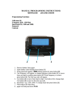
The 7798 I/SITE LAN (see Figure 1) consist of three major components:
✦
A single printed circuit board (PCB).
✦
A ViewCon and keypad for operator interaction and control.
✦
A plastic enclosure. The plastic enclosure provides for wall mounting or mounting
in a CSI environmental enclosure, a custom enclosure, or an equipment cabinet.
Printed Circuit Board
The I/SITE LAN uses a single printed circuit board. This board measures
6.50" L
×
8.00" W
×
1.75" D (16.51
×
20.32
×
4.44 cm) (see Figure 2). The I/SITE LAN
circuit board is mounted in a plastic enclosure measuring approximately
7.50" L
×
9.00" W
×
2.06" D (19.05
×
22.86
×
5.23 cm). Access to the component side of
the circuit board is accomplished via removal of the I/SITE LAN cover. To remove the
cover, first remove the two screws attaching the cover to the base, then disengage the
snap-on latch along the bottom of the cover. The cover can then be rotated out and lifted
off the mounting base at the top.
Figure 1. 7798 I/SITE LAN

Physical Description Installation Guide
4 7798 I/SITE LAN
Communication
The I/SITE LAN provides up to four ports as follows:
✦
A standard asynchronous RS485 subLAN port (TB2).
✦
A synchronous/asynchronous serial port (P4) or terminal block (TB4). Serial port
P4 provides access to an external modem through a 10-conductor ribbon cable.
Terminal block TB4 provides a direct wiring connection to an external modem.
Both P4 and TB4 are the same serial port; therefore, only one of these two connec-
tors should be attached to a modem.
P4 is used to provide simple and quick connection of an external modem via the
standard Dial/Dedicated modem cable CSI Model Number CBL048 (P/N 606105–
0017; 6 ft). When it is necessary to locate the modem more than 6 feet (1.82 m)
away from the I/SITE LAN, TB4 may be used for discrete wire connection of a
modem cable extending up to 50 feet (15 m) to the external modem. Low capaci-
tance shielded cable of 24 AWG (0.206 mm
2
) or larger is recommended for this
interface.
Figure 2. I/SITE LAN Controller Board
123 123 1234567891012345
TB1 TB2 TB3
P5
P3
P2
P1
U1 U2
U3
12 1
139
240
U6
Battery
+
6.5"
(16.51 cm)
8.0"
(20.32 cm)
7.5"
(19.05 cm)
6.0"
(15.24 cm)
U22
P4
TB4
1
10

Installation Guide Physical Description
7798 I/SITE LAN 5
✦
An asynchronous serial port (P3). This port provides access to an external PC,
external serial printer, or external asynchronous modem. When connecting a
modem to port P3, use CSI cable CBL074 (P/N 606105–0038). Use CSI cable
CBL072 (P/N 606105–0036) for DE-9, and CBL073 (P/N 606105–0037) for DB-25
connections to PC COM ports. CSI cable CBL081 (P/N 606105–0051) is used for
connection of serial printers.
✦
An expansion port (P2) provides serial communication with an optional controller
LAN expansion board. If the expansion board is installed, the I/SITE LAN can be
used as a peripheral controller for an I/NET system. (Refer to “Expansion Module”
on page 23.)
The I/SITE LAN can emulate one of four CSI Taps: 7801, 7810, 78061, and 78035. Tap
emulation is controlled by the settings manually entered through the ViewCon and by
the type of devices connected to the unit. Refer to “Tap Emulation” on page 22.
Communication Expansion Port
The communication expansion port (P2) provides connections to a CSI controller LAN
serial expansion board (RS485). The RS485 expansion board enables the I/SITE LAN to
be a peripheral controller for an I/NET system and still operate as a stand-alone unit. The
connector is in the upper-right corner of the controller (see Figure 2).
Reset
Upon power loss/restoration, the I/SITE LAN executes an automatic reset memory test
of RAM and EPROM. The test uses an array of RAM test bytes and a Checksum check
on the EPROM. If the check is successful, control and execution is passed to
programmed memory.
Memory
The I/SITE LAN provides support for several types of memory with variable amounts of
each. The current memory organization is listed in Table 1.
NOVRAM
The 7798 I/SITE LAN provides 512 bytes of non-volatile RAM (NOVRAM) storage. This
memory holds all parameters necessary to establish basic communication with the
controllers after a long-term power outage in which battery-backed static RAM content
is lost (refer to “Battery Backup” on page 6).
When the I/SITE LAN is emulating a 78061 Tap, it can store telephone numbers as a stan-
dard 78061 Tap would. Up to eight telephone numbers of at least 25 digits can be stored
in NOVRAM. (Refer to “Specifications” on page 43.)
Table 1. I/SITE LAN Memory
Socket Amount Memory type
U1 and U2 256KB Static RAM (Stores download software and database.)
U3 32KB EPROM (Stores boot firmware.)

Physical Description Installation Guide
6 7798 I/SITE LAN
Static RAM
The software design and memory organization supports the complete download of all
software, including revised LAN drivers that are invoked after completion of the down-
load. The downloaded software is held in static RAM. The software can be downloaded
while the I/SITE LAN is on-line with I/NET.
The content of static RAM is retained in the event of a power outage, as long as the
backup battery has power (i.e., up to 300 hours). When the battery power has depleted,
the content of static RAM is cleared (refer to “Battery Backup”, below).
EPROM
Erasable/programmable ROM (EPROM) stores the controller firmware, as well as a
firmware download handler and boot record firmware.
Battery Backup
The 7798 I/SITE LAN provides battery-backup of static RAM contents and of the
clock/calendar. The onboard NiCad rechargeable battery provides backup for up to 300
hours during a power failure.
Note:
The backup battery must be fully charged in order to provide the full span of backup power.
Due to normal discharge during product storage and shipment, the battery may not be fully
charged immediately following installation and power-up. You must allow the controller to
operate continuously for a minimum of seven days (168 hours) before depending on battery
backup.
Power Supply
Electrical power for the I/SITE LAN enters at the bottom-left edge of the board (TB1). A
single 24 VAC 50/60 Hz, 40 VA Class II external transformer provides input power for
the I/SITE LAN.
ViewCon
The ViewCon consists of an LCD and keypad (see Figure 3). The LCD is a 64
×
240 pixel
graphic display mounted behind the plastic cover. For the 7798 I/SITE LAN, the LCD
displays four text lines with up to 40 characters per line. The keypad is comprised of a
polyester membrane key panel that is mounted to the front panel of the plastic enclosure.
The keypad provides eight function keys identified as F1 through F8. The actual opera-
tion of the function keys varies dynamically based on the key function indication shown
on the LCD next to each respective key.
Refer to “ViewCon” on page 24 for more information about ViewCon operation.

Installation Guide Physical Description
7798 I/SITE LAN 7
Plastic Enclosure
The 7798 I/SITE LAN plastic enclosure provides a mounting base for the PCB and the
ViewCon (see Figure 4). The enclosure covers the entire PCB with a cutout on the
bottom side to expose the P3 connector. The enclosure base has a cutout for mounting
and entry/exit of wiring.
Figure 3. 7798 I/SITE LAN ViewCon
Figure 4. 7798 I/SITE Plastic Enclosure
F4
F2
F3
F1
F8
F6
F7
F5
9.00" (22.86 cm)
2.06"
(5.23 cm)
1.00"
(2.54 cm)
9.05" (22.99 cm)
6.00" (15.24 cm)
7.55"
(19.18 cm)
7.50"
(19.05 cm)
3.00"
(7.62 cm)
2.00" (5.08 cm)
(square)

Installation Procedures Installation Guide
8 7798 I/SITE LAN
Installation Procedures
Installing the I/SITE LAN
This section provides installation instructions for the 7798 I/SITE LAN. These instruc-
tions allow you to connect an external PC, modem, and printer to the 7798. LAN
connections for the sub-controller LAN and, optionally, the controller LAN are also
described. Use the following steps to install the 7798 I/SITE LAN.
Note:
Operational errors may occur if equipment is inadequately grounded. Symptoms may
include, but are not limited to: intermittent LAN or subLAN communication, improper
control actions, or loss of NOVRAM contents. Refer to “Grounding Requirements” on page
14 during equipment installation.
Initial Installation Procedure
1.
Ensure power is disconnected from the I/SITE LAN.
2.
Disconnect power to all devices that will be connected to the I/SITE LAN.
Warning:
Failure to disconnect power from all interconnected equipment when performing electrical
installation may result in electrical shock or burns.
3.
Attach the baseplate to the mounting location (keyhole mount). See Figure 4.
4.
If the controller LAN option is to be used, insert the expansion board into the
communication option port (P2) on the I/SITE LAN board. (Details on page 9.)
5.
Connect the external PC or modem. (Details on page 9 and 9.)
6.
Connect all sub-controller LAN cables at the PCB. (Details on page 12.)
7.
Connect the power supply to the I/SITE LAN. (Details on page 13.)
8.
Attach the I/SITE LAN plastic cover (and its attached motherboard PCB) to the
baseplate.
9.
Reconnect power to devices that are connected to the I/SITE LAN.
10.
If the controller LAN option is used, set the I/SITE LAN station address and the
data communication rates. (Details on page 15.)
11.
If the controller LAN option is to be used, connect the controller LAN cable to TB1
on the expansion board. (Details on page 12.)
Note:
Procedures for setting the controller LAN address, Tap emulation, Tap baud rate, and
controller LAN baud rate, begin from the DCU setup screen. If the I/SITE LAN is at boot
control, the DCU setup screen is accessed by selecting “DCU setup” from the banner screen.
If software has already been downloaded to the I/SITE LAN, then the DCU setup screen is
accessed by selecting “Sign-on” from the banner screen; “Parameter edit” from the function
select screen; and then “DCU setup/status” from the parameter edit screen.

Installation Guide Installation Procedures
7798 I/SITE LAN 9
Connecting a Controller LAN Expansion Board
Warning:
Ensure that no power is connected to the I/SITE LAN when performing these procedures.
Failure to disconnect power from all interconnected equipment when performing electrical
installation may result in damage to the components, electrical shock, or burns.
1.
Connect port P1 on the expansion board to port P2 on the face of the I/SITE LAN
PCB.
2.
Secure the expansion board with the provided two standoffs and attaching screws.
Connecting an External PC
Port P3 provides asynchronous communication through a nine-conductor D-Subminia-
ture connector. This port allows the direct connection of a PC to the I/SITE LAN. The
circuit connections at this port are typical of the serial COM port on the PC. A 6-foot
(1.82 m) serial communication cable with low-profile right-angle D-Sub connections
can be obtained from CSI.
When connected directly to a PC, the I/SITE LAN performs the functions of a 7801 Tap
without consuming an additional LAN address. Use CSI cable number CBL072 (P/N
606105–0036) for a 9-pin PC connection, and CSI cable number CBL073 (P/N 606105–
0037) for a 25-pin PC connection.
1.
Connect the cable from the PC COM port to port P3 on the I/SITE LAN (accessible
through cutout at bottom of plastic cover).
2.
Configure the I/SITE LAN for 7801 Tap emulation (“Station type” function). Refer
to “Setting the Tap Emulation” on page 15.
3.
Set the baud rate on the I/SITE LAN (“Tap speed” function) to the appropriate
baud rate using the ViewCon. Refer to “Setting the Tap Baud Rate” on page 16.
Connecting an External Modem
Integrated Dial
When the I/SITE LAN is set to emulate a 7801 Tap, the “Integrated Dial” function (i.e.
one-way dial from the host PC to the I/SITE LAN) is supported. Connect an external
Hayes-compatible modem to port P3 for this type of communication. Port P3 provides
a 9-conductor D-Subminiature connector (see Figure 5). CSI cable number CBL074
(P/N 606105–0038) is available from CSI for an asynchronous modem connection to P3.
Figure 5. RS232 Connection
P3 PIN Function
1 Not Used
2 RXD Receive Data
3 TXD Transmit Data
4 DTR Data Terminal Ready
5 GND Signal Common
6 Not Used
7 RTS Request to Send
8 CTS Clear to Send
9 Not Used
1 5
6 9

Installation Procedures Installation Guide
10 7798 I/SITE LAN
Auto-dial/Auto-answer (AD/AA)
When the I/SITE LAN is set to emulate the 78061 Tap, the AD/AA function (i.e. two-way
dial between the host PC and the I/SITE LAN) is supported. Use the following types of
modems for AD/AA communication:
✦
Synchronous — Use a synchronous modem when the controller is loaded with an
I/NET version 4.x or earlier binary file. The controller must also have I/NET
version 4.x boot firmware (EPROM).
✦
Asynchronous — Use an asynchronous modem when the controller is loaded with
an I/NET 2000 binary file. The controller must also have I/NET 2000 boot firm-
ware (EPROM).
Note:
Ensure that all AD/AA Taps within your I/NET system are configured to use the same
communication protocol — either synchronous, or asynchronous. Mixing AD/AA protocols
will cause communication errors.
I/NET 2000 is compatible with I/NET version 4.x Tap and controller binary loads. There-
fore, when synchronous AD/AA communication is required on an I/NET 2000 system (for
example, when using a 78040, 78050, or 78060 Tap), you must continue to use I/NET
version 4.x Tap and controller binary loads.
Connectors P4 and TB4 allow you to connect an external Hayes-compatible modem to
the 7798. Both P4 and TB4 are the same serial port and only one connector should be
attached to a modem. Port P4 provides a 10-conductor ribbon connector. Terminal
block TB4 provides a direct wiring connection. Figure 6 shows each connector.
CSI cable number CBL048 (P/N 606105–0017) is available from CSI for a modem
connection to P4. Use discrete wiring to connect a modem to TB4.
The Model 7798-C I/SITE LAN (CE marked version) includes a ferrite clamp (CSI P/N
602711–0004). If using the AD/AA port (P4/TB4), the ribbon cable from the port should
be passed through the clamp with the clamp positioned just outside the rear of the 7798
enclosure.
Direct Connect
When the I/SITE LAN is set to emulate a 78035 Tap, the “Direct Connect” function (i.e.,
communication over continuously active data lines) is supported. Connect an external
Hayes-compatible modem to port P4 or TB4 for this type of communication. Port P4
Figure 6. Port P4 and Terminal Block TB4 Connections
12345678910
P4
TB4
Pin Description
1 TXD - Transmit Data
2 RXD - Receive Data
3 RTS - Request To Send
4 CTS - Clear To Send
5 DTR - Data Terminal Ready
6 DCD - Data Carrier Detect
7 RXC - Receive Clock
8 GND - Signal Common
9 TXC - Transmit Clock
10 +12V (strapable - not used)
10
1

Installation Guide Installation Procedures
7798 I/SITE LAN 11
provides a 10-conductor ribbon connector. Terminal block TB4 provides a direct wiring
connection. Figure 6 shows each connector. CSI cable number CBL048 (P/N 606105–
0017) is available from CSI for connection to P4.
Modem Installation
The following installation procedures are used for all three types of modem connections:
1.
Connect the modem to the appropriate serial port connector.
2.
If you are connecting a modem to the AD/AA port (P4/TB4) on the Model 7798-C
I/SITE LAN (CE marked version), pass the ribbon cable from the port through the
included ferrite clamp. Position the clamp just outside the rear of the 7798 enclo-
sure.
3. Configure the I/SITE LAN Tap emulation (“Station type” function). Refer to
“Setting the Tap Emulation” on page 15.
4. Set the baud rate on the I/SITE LAN (“Tap speed” function) to the appropriate
baud rate using the ViewCon. Refer to “Setting the Tap Baud Rate” on page 16.
5. Refer to “Tap Emulation” on page 22 for modem setup information.
Connecting an External Serial Printer
Port P3 provides asynchronous communication through a nine-conductor D-Subminia-
ture connector. This port allows the direct connection of a serial printer to the I/SITE
LAN. A 6-foot (1.82 m) serial printer cable with D-Sub connections can be obtained
from CSI.
When connected directly to a serial printer, the I/SITE LAN performs the functions of a
7810 Printer Tap. The I/SITE LAN must be configured as either a 779801, 779803, or
779806 to enable the 7810 Printer Tap emulation (refer to “Setting the Tap Emulation”
on page 15). Use CSI cable number CBL081 (P/N 606105–0051) for a serial printer
connection.
The 7798 uses the following default settings when connected to a printer:
✦ 1 stop bit
✦ no parity
✦ all eight group 1 masks enabled (I/NET)
Connect a serial printer to the 7798 I/SITE LAN using the following procedure:
1. Ensure the I/SITE LAN is set to emulate either the 7801, 78061, or 78035 Tap. Refer
to “Setting the Tap Emulation” on page 15.
2. Set the Tap baud rate to match the baud rate of the serial printer. Refer to “Setting
the Tap Baud Rate” on page 16.
3. Connect the cable from the serial printer to port P3 on the I/SITE LAN (accessible
through cutout at bottom of plastic cover).

Installation Procedures Installation Guide
12 7798 I/SITE LAN
Connecting to the Sub-controller LAN
Note: Operational errors may occur if equipment is inadequately grounded. Refer to “Grounding
Requirements” on page 14 during equipment installation.
The I/SITE LAN sub-controller LAN can accommodate up to 32 MRs, DP sub-control-
lers, ASCs, or a combination of each residing on the sub-controller LAN (see Figure 7).
A 5-pin terminal block provides the RS485, shielded twisted-pair cable connections on
port TB2.
1. Connect the Com + line to terminal 1.
2. Connect the Com – line to terminal 2.
3. Connect the return Com + line to terminal 4 (closed loop only).
4. Connect the return Com – line to terminal 5 (closed loop only).
Connecting to the Optional Controller LAN
Note: Operational errors may occur if equipment is inadequately grounded. Refer to “Grounding
Requirements” on page 14 during equipment installation.
The controller LAN address and baud rate should be set after first powering up the unit and
prior to connecting the unit to the controller LAN. Refer to “Setting the Controller LAN
Address” on page 15 and “Setting the Controller LAN Baud Rate” on page 16 for more
information.
Figure 7. Sub-controller LAN Connection
12345
TB2
12345
Sub-controller LAN
(Open Loop)
LAN +
LAN –
SHLD
ALT +
ALT –
MR
DPU
ASC
LAN +
LAN –
SHLD
ALT +
ALT –
TB2
Sub-controller LAN
(Closed Loop)
Earth ground at only
one location, typically
at the I/SITE.
MR
DPU
DPU
MR
ASC
Earth ground at only
one location, typically
at the I/SITE.

Installation Guide Installation Procedures
7798 I/SITE LAN 13
The controller LAN port is located along the lower left side of the optional expansion
board. It provides synchronous data link control (SDLC) communication and supports
the primary RS485 controller LAN connection.
A five-pin terminal block (TB1) provides connection of the RS485 shielded twisted pair
cable (see Figure 8).
1. Connect the Com + line to terminal 1.
2. Connect the Com – line to terminal 2.
3. Terminals 3, 4, and 5 are not used.
Caution: Ensure that you connect terminal 1 to 1, and terminal 2 to 2 on all controllers. The LAN
cable shield must be grounded at only one location along the controller LAN (typically at
the I/SITE LAN).
Connecting the Power Supply
Note: Operational errors may occur if equipment is inadequately grounded. Refer to “Grounding
Requirements” on page 14 during equipment installation.
Electrical power connections for the 24 VAC input power are located along the lower-left
corner of the controller at TB1 (see Figure 9).
Figure 8. Controller LAN Connections
P1
12345
TXD
RXD
DCD
RS485 Port
TB1
COM +
COM –
Earth ground shield at only one
location on the controller LAN
(typically at one end).
Controller LAN
Controller LAN
Expansion Board
Splice shield drains at each
controller location.
Note:

Installation Procedures Installation Guide
14 7798 I/SITE LAN
Caution: Before you apply power to the I/SITE LAN, ensure that the 24 VAC secondary leads are
connected only to TB1. Connection to any other terminal block will damage the I/SITE
LAN. The transformer secondary leads (24 VAC) should not be connected to ground.
1. Connect the 24 VAC input leads from a separate, isolated 24 VAC/40VA trans-
former, to terminals 1 and 2 of terminal block TB1.
2. Connect terminal 3 of TB1 to a good earth ground using 14 AWG wire (2.081 mm
2
wire).
Grounding Requirements
Earth Ground
To ensure proper operation of the controller, it is imperative that the unit be correctly
grounded. The controller chassis will not provide ground for the input power circuit and
interconnected sensors/devices. Terminal block TB3 must be connected to an Earth
ground.
LAN Ground
Note: This procedure applies to all LAN and subLAN connections.
✦ Ensure that the subLAN cable shield drain wire is not connected to the controller
subLAN terminal block.
✦ Shield drain wire continuity must be maintained as the subLAN cable passes
through each controller. Shield drain wires from each controller subLAN cable
must be spliced together, insulated, and tied back such that wires do not come in
contact with ground or any conductive surface within a controller.
✦ Connect the shield drain wire directly to Electrical Service Earth Ground at only
one end of the cable (e.g., typically at the I/SITE LAN).
Figure 9. I/SITE LAN Power Connection
24VAC
GND
123 123 1234567891012345
TB1 TB2 TB3
P5
P3
12 1
24 VAC
Transformer
24VAC
P4
TB4
Earth
Ground
1
10
/