Amerec AI Boiler, "AI12 Through AI48" Operating instructions
- Type
- Operating instructions

4211-1951 04/19/19
INSTALLATION INSTRUCTIONS
FOR THE AI SERIES STEAM BOILER
WITH T100-B TOUCH CONTROL
MODELS AI12, AI18 & AI24 and
MODELS AI30, AI36, AI42 & AI48

4211-1951 04/19/18 Page 2
AI SERIES STEAM BOILER WITH T100 CONTROL
INSTALLATION INSTRUCTIONS

AI SERIES STEAM BOILER WITH T100 CONTROL
INSTALLATION INSTRUCTIONS
4211-195 1 04/19/18 Page 3
IMPORTANT SAFETY INSTRUCTIONS
READ AND FOLLOW ALL INSTRUCTIONS.
WARNING - To reduce the risk of injury, do not permit children to use this product unless they are closely
supervised at all times.
WARNING - To reduce the risk of injury:
a. The wet surfaces of steam enclosures may be slippery. Use care when entering or leaving.
b. The steam head is hot. Do not touch the steam head and avoid the steam near the steam head.
c. Prolonged use of the steam system can excessively raise the internal human body temperature and
impair the body’s ability to regulate its internal temperature (hyperthermia). Limit your use of steam to
10 - 15 minutes until you are certain of your body’s reaction.
d. Excessive temperatures have a high potential for causing fetal damage during the early months of
pregnancy. Pregnant or possibly pregnant women should consult a physician regarding correct
exposure.
e. Obese persons and persons with a history of heart disease, low or high blood pressure, circulatory
system problems, or diabetes should consult a physician before using a steam bath.
f. Persons using medication should consult a physician before using a steam bath since some medication
may induce drowsiness while other medications may aff ect heart rate, blood pressure and circulation.
WARNING - Hyperthermia occurs when the internal temperature of the body reaches a level several
degrees above the normal body temperature of 98.6°F (37°C). The symptoms of hyperthermia include an
increase in the internal temperature of the body, dizziness, lethargy, drowsiness and fainting. The eff ects of
hyperthermia include:
a. Failure to perceive heat
b. Failure to recognize the need to exit the steam bath
c. Unawareness of impending risk
d. Fetal damage in pregnant women
e. Physical inability to exit the steam bath
f. Unconsciousness
WARNING - The use of alcohol, drugs or medication can greatly increase the risk of hyperthermia.
SAVE THESE INSTRUCTIONS

4211-1951 04/19/18 Page 4
AI SERIES STEAM BOILER WITH T100 CONTROL
INSTALLATION INSTRUCTIONS
SAVE THIS MANUAL
Thank you for purchasing your new Amerec steam boiler.
If we can be of any assistance do not hesitate to call our Technical Support department at 1-800-363-0251.
FOR THE SAFETY OF YOU AND YOUR FAMILY OR CUSTOMERS, PLEASE READ FOLLOWING WARNINGS AND ALL INSTRUCTIONS BEFORE
USING YOUR STEAMBATH. POST "STEAMBATH INSTRUCTIONS" LABEL OUTSIDE STEAMBATH FOR SAFETY WARNINGS.
WARNING
Electric Shock Hazard - High voltage exists within this equipment. Disconnect all electrical power before servicing the boiler. All installation and service
to this equipment should be performed by qualifi ed license personnel in accordance with local and national codes. There are no user serviceable parts
in this equipment.
Electrical grounding is required on all Amerec steam bath boilers.
The boiler is designed for hookup with copper wire only, 75°C or better.
Wire the controls exactly as described. Do not connect any additional wiring or power supplies to the controls or their terminals in the boiler.
All plumbing must be installed by a licensed plumber in accordance with all applicable local and national codes.
Install indoors only. Protect from freezing. Boiler must be level side to side and end to end.
The pressure relief valve and generator drain must be installed in such a fashion that the risk of scalding is reduced to a minimum. Draining these
outlets into the steam room may present a scald hazard and may damage materials used to construct the room.
Be certain that steambath enclosures are properly sealed to avoid water damage from escaping steam. It is recommended that 100% silicone caulk be
used to seal all pipes and fi ttings. Steam must be prevented from escaping into the wall cavity.
Avoid traps and valleys in the steam line where water could collect and cause a steam blockage. The hot steam line must be insulated against acciden-
tal user contact.
Centering the steam pipe is critical in rooms made of plastic, acrylic, resin, fi berglass or similar materials. Allowing the steam pipe to touch materials not
rated 240°F (115°C) or higher will result in damage to these materials.
Do not install the steam head near bench(es) or where steam may spray or where condensation will drip on the user as this will present a scald hazard.
Be careful when entering a steam bath. Escaping steam from an overheated steam room may cause injury.
Scald Hazard: Do Not Touch the steam head or trim during operation as they are HOT. Stay at least 12 inches (305 mm) away from the hot steam
escaping from the steam head.
Children should only use the steam bath under close adult supervision.
Do not exceed 30 minutes in a steam bath. Excessive exposure can be harmful to your health. Excessive exposure can produce a rapid pulse, light-
headedness, weakness or fainting. If you become uncomfortable or experience any of the above conditions exit the steam bath immediately.
Steam baths can put undue stress on the body. Therefore a steam bath should be used only under a doctor's direction if you:
Are in generally poor health Are pregnant
Are under the care of a physician Have a heart condition
Have circulatory problems Have high blood pressure
Have diabetes Are using medication
DO NOT use the steam bath if you:
Are under the infl uence of drugs Are under the infl uence of alcohol

AI SERIES STEAM BOILER WITH T100 CONTROL
INSTALLATION INSTRUCTIONS
4211-195 1 04/19/18 Page 5
CAUTION
BEFORE INSTALLING YOUR AI BOILER AND T100 CONTROL
VERIFY YOUR BOILER AND CONTROL ARE DESIGNED FOR YOUR VOLTAGE
Boilers designed for North American power are available in 208 and 240VAC for single phase and in
208, 240 and 480VAC for three phase line voltage. Any boiler may be used on a lower voltage (which also
results in a lower wattage) but use on a voltage higher than about 10VAC above the rating may result in
damage to the heating elements.
All controls for North American boilers (including the T100’s daptor box) will operate on 120VAC 60Hz.
Boilers designed typical international voltages of 220/380V~, 230/400V~ or 240/415V~ operate at
240V~ N for single phase mains and 415V~ for three phase mains. These boilers may be used safely at the
common lower voltages. All controls for these boilers operate on 230V~ N 50Hz.
The T100 boiler interface unit is powered by a plug-in wall adaptor for 120VAC. For use with international
voltage boilers, a wall adaptor suitable for 230V~N will be required. Contact Support for assistance.
These instructions include information for all models with both North American and (metric/international) values.
Be careful to use the correct values for you installation.
These instructions cover using the T100 with the AI boilers. You should fi rst install the boiler per Amerec’s
4211-1631 boiler installation instructions and you should have Amerec’s 4209-53 T100 owner’s manual &
operating instructions available when installing the T100.
For further assistance, contact Technical Support:
Technical Support
17683 128th Place NE, Bldg C
Woodinville, WA 98072
USA
email: [email protected]
phone 425.951.1120
fax: 425.951.1130

4211-1951 04/19/18 Page 6
AI SERIES STEAM BOILER WITH T100 CONTROL
INSTALLATION INSTRUCTIONS
GENERAL INFORMATION: The AI Commercial Steam Boiler is a low pressure boiler, UL/CUL Listed, built to NEC requirements and using a
National Board Registered and ASME certifi ed H stamped pressure vessel.
The boiler has all steel construction with powder coated fi nish on visible surfaces and stainless steel mounting feet to minimize the risk of cor-
rosion. The mounting feet hold the boiler one inch (25 mm)above the fl oor to allow cleaning the fl oor below it and to further prevent corrosion.
This also allows the boiler to sit directly on a combustible surface without additional protection. The feet extend beyond the sides of the boiler
chassis and have clearance holes to allow securing the boiler in place using ¼” (6.4 mm) bolts.
AI Steam Generators must be installed by a licensed plumber and electrician to local and national codes.
Exposed plumbing may be over 200°F (93°C) during normal operation and can present a severe burn hazard.
Be sure to protect people from accidental contact!
AI Steam Boilers are intended for indoor use only.
Install upright and level side to side and front to back.
Not for space heating purposes.
Protect from freezing.
The steam generator is designed to sit directly on a hard level surface. The mounting location must be suitable to safely support over 125 lb.s
(57 kg) for models AI12-AI24 and over 150lb.s (68 kg) for AI30-AI48. The boiler must be mounted upright and level and prevented from mov-
ing. Ensure that the boiler is mounted high enough above the drain receptacle to allow proper drain fl ow. The weight of the boiler is generally
suffi cient to prevent movement. Use ¼” bolts through the holes provided in the boiler’s feet to secure it in place fl oor if necessary.
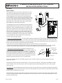
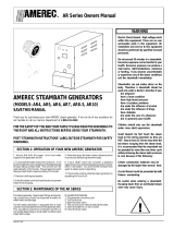
AI Commercial Steam Boilers are factory assembled and tested and ready to install. The boiler’s
control circuit is protected by a 250VAC 3A non-time-delay fuse installed in the front panel of the
boiler’s electrical box. No other fusing is installed in the steam boiler.
All electrical access is from the left side and front end (as viewed at right). Up to 480VAC may be
exposed during servicing. Leave space for service access: at least 18” (460 mm) to front and left
side, 6” (150 mm) above the pressure switches and valves.
Standard boiler equipment:
• Manual operation (boiler mounted RUN switch and manual ball valve drain) and single steam room
(one steam valve, one temperature sensor, one T100, two steam heads). Switches allowing manual
heat and water control during routine service, lights indicating heat and valve operating status and
self-check fault codes.
Optional equipment:
• Second steam room (second steam valve, T100 and temperature sensor, two steam heads) factory installed only!
• RUN CLOCK (7-day or 24 hour clock for boiler ON/OFF scheduling, does not affect the T100).
• AUTODRAIN (24 hour clock plus electronic drain valve).
The T100 control’s interface box is connected to the boiler’s low voltage Class 2 control circuit during installation using a factory supplied cable.
An access hole and knockouts, ½” trade size, are provided for room control wiring.
The T100 may be mounted inside or outside the steam room and its temperature sensor must be mounted inside the steam room. Their
temperature sensors require factory supplied 25 foot (4.6 m) long cables for connection to the T100’s adapter box and a 25 foot (4.6 m) long
shielded cable is supplied for connecting the T100 to it’s adapter box..
Left Front

AI SERIES STEAM BOILER WITH T100 CONTROL
INSTALLATION INSTRUCTIONS
4211-195 1 04/19/18 Page 7
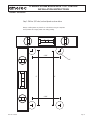
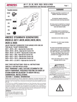
ELECTRICAL
ROOM CONTROLS
Each steam valve outlet is to be used for a single steam room. Each
room requires one temperature sensor mounted in the room and one
T100 room control mounted inside or outside the steam room. The
T100 and temperature sensor connect to a wall mounted interface
box. The interface connects to the circuit board in the boiler’s electrical
enclosure. To reduce the risk of electrical interference between circuits,
do not run the low voltage control cables inside the same conduit as
high voltage circuits. Avoid running control cables closely alongside
high voltage wiring in cable troughs and raceways.
Two independent control circuits are available for two steam outlets to
supply two separate steam rooms. If only one valve is installed on the
steam boiler, it will be controlled by the ROOM 1 circuit with the T100’s
interface box connected to the T’STAT terminal block at the upper left
edge of the printed circuit board (PCA) located in the boiler’s electrical
enclosure. When the (optional) second steam outlet is provided, the
second room’s control interface connects to the T’STAT terminal block
near the center left edge of the PCA in the same manner as the ROOM
1 circuit described here. Follow all wiring and PCA jumper setting
instructions closely for proper operation.
1. INSTALL THE T100 INTERFACE BOX The T100’s interface box will be connected to the T100 control, the room temperature sensor, and
the steam boiler using the supplied 25 foot (7.6 m) cables. It also requires a 9VDC power adapter (provided) which connects to a nearby
120VAC or 230V~ outlet. Select a location which is convenient to the boiler, power, control and temperature sensor then mount the box on
the wall. This location should be dry and keep the box safe from damage.
• Remove the box’s cover before mounting by gently pulling out on the sides of the box cover until it slides off.
• Locate the two mounting holes inside the box then use screws or other appropriate mounting methods to secure the box to the wall.
• Leave the cover off until all cables and power are connected and the installation has been shown to be working correctly.
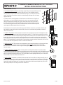
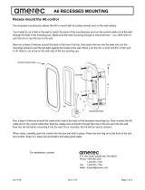
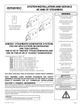
2. TEMPERATURE SENSOR INSTALLATION Before installing the sensor,
make sure it has a yellow band on the tubing on the back of the assembly. If not,
contact technical support at 1-800-363-0251 for assistance. The temperature
sensor must be mounted in the steam room. Cut a 7/8” (22 mm) diameter hole
in the steam room wall to mount the sensor. It is recommended that the sensor
be mounted 6” (152 mm) down from the ceiling, but not directly over the steam
dispersion head and not more than 7 feet (2.1 m) above the fl oor.
Do not cover or enclose the sensor: if the airfl ow across the sensor is blocked or reduced, the room may overheat or suffer large
temperature variations.
String the sensor cable from the sensor location through ½” (12 mm) holes in the wall studs or ceiling joists to the adapter box location.
Leave 12” (300m) of slack at the sensor location. Note: Do not staple through or otherwise damage the cable. Use a factory supplied
sensor cable only.
In the steam room: Plug the temperature sensor into the sensor cable. The cable and the sensor connectors are designed to lock together
when properly aligned. Run a bead of 100% silicone caulk around the underside of the sensor head then carefully feed the cable and sensor
through the hole and attach the sensor in place.
At the interface box: Connect the sensor cable’s end plug into its socket on the box’s circuit board. The socket is directly above the board’s
T100 jack. Orient the cable end to match its socket and insert it until the end locks in place. Use a cable strain relief (provided) to secure
the cable to the interface box.
TEMPERATURE
SENSOR
PROBE MUST BE
POINTED DOWN
STEAM ROOM WALL
SILICONE CAULK
SENSOR
CABLE
7/8” HOLE
2
1
3
2
1
K1
J2
TB1
TB2
J1
K2
T100
LOW VOLTAGE
ROOM LIGHT
BOILER T-STAT
SVC
TEMP SENS
T100
AT TEMP
SENSOR
INTERFACE
POWER ADAPTOR
BOILER TEMPERATURE
SENSOR BYPASS
LOW VOLTAGE
LIGHT
(OPTION)
BOILER ELECTRICAL BOX
05

4211-1951 04/19/18 Page 8
AI SERIES STEAM BOILER WITH T100 CONTROL
INSTALLATION INSTRUCTIONS
Sensor
Bypass
Low Voltage
Room Light
(Option)
ROOM CONTROLS (continued)
3. T100 CONTROL INSTALLATION The low voltage control T100s can be mounted directly to a fi n-
ished wall. Connect the control to the interface using the 25 foot (7.6 m) shielded 8 conductor
cable (provided). String the cable from the control location through
1
/
2
” (13 mm) holes in the wall
studs or ceiling joists to the interface. Note: Do not staple through or damage cable. Use factory
supplied cables only.
In the steam room: A mounting template is included at the end of this document. Using the sup-
plied template, cut a hole in the fi nished wall where the control is to be mounted and pull the
cable end out through the mounting hole. Plug the control cable into the cable on the back of
the T100 control housing. Run a bead of 100% silicone caulk around the perimeter on the back
of the control housing and insert the T100 into the fi nished wall, center the control and tape the
control against the fi nished wall while the silicone hardens.
At the interface box: Connect the control cable’s plug into the T100 jack on the box’s circuit board. Orient the cable
end to match its socket and insert it until the end locks in place. Use a cable strain relief (provided) to secure the
cable to the interface box.
4. CONNECT TO BOILER A 25 foot (7.6 m) three conductor cable is provided to connect the T100 adapter box to the
AI boiler steam boiler. String the cable from the control location through
1
/
2
” (13 mm) holes in the wall studs or ceiling
joists to the interface. Note: Do not staple through or damage cable. Install the cable in the interface’s BOILER T’STAT
terminal block by pressing the orange tab, inserting the stripped end of one cable conductor, then releasing the tab.
Repeat until all three wires are secured. Repeat the process to connect the other end of the cable to the boiler circuit
board’s T’STAT terminal block. Be sure the position 1 at the interface connects to position 1 at the boiler, 2 to 2 and 3 to
3! Use a cable strain relief (provided) to secure the cable to the interface box.
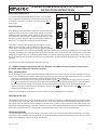
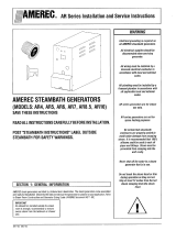
5. INSTALL BYPASS The T100 connects to its own temperature sensor through the interface so the normal boiler tem-
perature sensor is not connected. Instead, a sensor bypass (supplied) must be plugged into the TEMP SENS
jack on the boiler’s circuit board as shown at right. Orient the bypass plug to match the jack and insert it until the
end locks in place.
6. CONNECT INTERFACE POWER A power converter provides low voltage to the interface for normal operation.
Connect the power converter into an outlet near the interface box then run its cord through a hole in the interface box and
connect it to the power jack on the interface circuit board (between the T-STAT terminal block and the T100 jack). When
power is connected, the PWR light (above the T’STAT terminal block) should light bright and steady. Use a cable strain
relief (provided) to secure the cable to the interface box.
7. LIGHT (OPTION) The interface circuit board includes a terminal block for use with a low voltage room light, such as
Amerec’s Chormatherapy kit (contact Support for more information). Connect the interface in line with one of the light’s
power leads as shown at right and connect those leads to the LOW VOLTAGE RM LIGHT terminal block by pressing an
orange tab, inserting the stripped end of a conductor, then releasing the tab. After connecting both wires, use a cable
strain relief (provided) to secure the light wires to the interface box.
2
1
3
2
1
K1
J2
TB1
TB2
J1
K2
LOW VOLTAGE
ROOM LIGHT
BOILER T-STAT
SVC
TEMP SENS
2
1
3
2
1
K1
J2
TB1
TB2
J1
K2
LOW VOLTAGE
ROOM LIGHT
BOILER T-STAT
SVC
TEMP SENS

AI SERIES STEAM BOILER WITH T100 CONTROL
INSTALLATION INSTRUCTIONS
4211-195 1 04/19/18 Page 9
BOILER CIRCUIT BOARD SET-UP
The T100 will control the steam bath through the boiler’s T’STAT terminal
block. To ensure the T100 will function correctly, make sure the bath On/Off
control switch on the boiler’s circuit board is set with all positions down as
shown at right.
BOILER OPERATION
NOTE: When the boiler is started with an empty tank, the room steam valves
will open to release the air pressure created during water fi ll. Once the tank
has fi lled, the valves will operate normally, opening only when steam needs
to be released to a room to increase its temperature. Also, whenever a steam
valve opens to release steam to a room, the boiler heating is disabled for a
few seconds. This is designed to increase the elements’ working life.
Set the BOILER OPERATION switch to the right (red showing) or set the
optional run clock to a “RUN” position. The BOILER ON light, both room
STEAM VALVE OPEN lights and the WATER VALVE OPEN light should turn
on, one heat contactor will close and the boiler will start fi lling with water. The water will become visible in the water gage a few seconds later. In
a short time, the feedwater valve and its light will turn off, the steam valve lights will turn off, the BOILER HEATING light will turn on and second
heating element contactor will close. The boiler will continue heating until it reaches its operating pressure of approximately 4 to 6 psi, then the
BOILER HEATING light and one contactor will turn off. During normal operation, the water level should always be visible in the lower half of the
gage glass.
Check for steam and water leaks. Repair any leaks before continuing.
Note: The boiler will operate a steam bath only while is it in RUN mode. The T100 does not sense if the boiler is running or not, so
the T100 will operate normally even if the boiler is turned off.
VERIFY T100 INSTALLATION
After all connections have been made, and the boiler operation verifi ed (per previous section and the 4211-1631 boiler installation instructions),
make sure the T100 interface box is turned on (PWR light on) and power is turned on to the room light (if installed) and the boiler is set to RUN.
• On the boiler: the room steam valve should be closed and the ROOM STATUS lights should be off.
• At the Control: touch the bottom of the T100 screen to light the display. With the icon lit brightly on the display, press the OK switch. A
small should light below the T100 display, the interface board’s two lights should be lit (left light shows power is on, right light indicates
the steam room should be heating), the room steam valve should open and the boiler’s ROOM STATUS lights should light steadily.
• (Optional) Room Light (if installed): With the T100 display lit, press the T100’s switch. There should be a small icon lit below the
display and the room light should turn on.
If there are any blinking lights or other failures, recheck all connections. Contact Technical Support for assistance.
OPERATING INSTRUCTIONS
The AI boiler steam generation is based on two operating systems. The fi rst is the boiler itself, maintaining water levels and boiling the water to
create steam for use in a steam bath. The second is the steam room control circuit, maintaining a comfortable steam bath by releasing steam
from the boiler only when needed to raise the temperature in the steam room. The boiler’s control circuit board is used for both systems so the
boiler must be running before starting a steam bath. And the boiler may run continuously without affecting the steam room temperature. In this
way the boiler can be left running so it is ready to produce steam immediately when the T100 is used to start a steam bath.
STEAM ROOM OPERATION
The steam room begins heating when the thermostat or room switch is used to “turn on” the steam bath. While the steam bath is on, steam is
released to the room as needed to bring the temperature up to the thermostat setting. When the boiler supplies two rooms, the rooms operate
identically but independently. Only one room will be described here.
TEMP
SENSOR
T’STAT
ROOM
SWITCH
REFRESH
SWITCH

4211-1951 04/19/18 Page 10
AI SERIES STEAM BOILER WITH T100 CONTROL
INSTALLATION INSTRUCTIONS
The T100 is the thermostat, controlling the steam bath temperature. Refer to Amerec doc. 4209-53 for the
detailed T100 operating instructions.
The T100 lets the user start and stop the steam bath, adjusts the bath temperature, and controls how long the
bath runs before automatically stopping. When the bath is turned off, the boiler’s steam valve will remain closed
and the corresponding ROOM STATUS LEDs on the boiler will remain turned off.
Technical Support
17683 128th Place NE, Bldg C
Woodinville, WA 98072
USA
email: [email protected]
phone 425.951.1120
fax: 425.951.1130

AI SERIES STEAM BOILER WITH T100 CONTROL
INSTALLATION INSTRUCTIONS
4211-195 1 04/19/18 Page 11
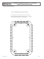
Always confi rm pattern as printed is to scale before using as a template.
Some printers will change pattern size during printing.
APPENDIX 2: T100 ROUGH-IN
2 5/8”
2 5/8”
5”
5”
3/4”
Step 1: Drill four 3/4” holes, level and plumb as shown below

4211-1951 04/19/18 Page 12
AI SERIES STEAM BOILER WITH T100 CONTROL
INSTALLATION INSTRUCTIONS
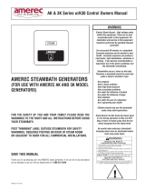
Note: dashed line shows outside edge of T100 control for reference
Always confi rm pattern as printed is to scale before using as a template.
Some printers will change pattern size during printing.
APPENDIX 2: T100 ROUGH-IN (continued)
Step 2: Cut straight edges from hole to hole as shown.
CUT
CUT
CUT
CUT
-
 1
1
-
 2
2
-
 3
3
-
 4
4
-
 5
5
-
 6
6
-
 7
7
-
 8
8
-
 9
9
-
 10
10
-
 11
11
-
 12
12


Amerec AI Boiler, "AI12 Through AI48" Operating instructions
- Type
- Operating instructions
Ask a question and I''ll find the answer in the document
Finding information in a document is now easier with AI
Related papers
-
 Amerec AK Series Owner's manual
-
 Amerec Time Clock Installation guide
-
 Amerec AK Series Installation & Owner's Manual
-
 Amerec AR10 Owner's manual
-
 Amerec AV2/120-2T Generator Operating instructions
-
Amerec K2 User manual
-
 Amerec AX Control "A6" Operating instructions
-
 Amerec AR Generator, "AR4 Through AR10" Operating instructions
-
 Amerec AT & 3T Generator "Ganging" Operating instructions
-
 Amerec AK & 3K Generator "Ganging" Operating instructions


Other documents
-
Kohler 5533-NA Installation guide
-
Kohler 5533-NA Installation guide
-
VIDALUX Vida-3kwGen User manual
-
Honeywell T100C User manual
-
 TruAudio T100 Operating instructions
-
Jacuzzi SteamPro User manual
-
SICK Efficient Solutions for the Power Industry User guide
-
Grant Combi 36e Installation And Servicing Instructions
-
-
Honeywell T104F User manual
