Page is loading ...

AMEREC STEAMBATH GENERATOR
(MODEL: AV2, 2KW/120 VOLT)
SAVE THESE INSTRUCTIONS
READ ALL INSTRUCTIONS CAREFULLY BEFORE INSTALLATION.
POST "WARNING" LABEL OUTSIDE STEAMBATH FOR SAFETY
WARNINGS. REQUIRED POSTING ON DOOR OF STEAM ROOM
OR ADJACENT TO DOOR FOR ALL COMMERCIAL
INSTALLATIONS.
4211-123 10-15-08
AMEREC steam generators are listed by Underwriters Laboratories. The steam generators come assembled
and ready for installation. Check that the size and rating of the generator is suitable for your application.
IMPORTANT
An exhaust fan installed outside the steam
room is strongly recommended to remove
excess steam from the bathroom or shower
area.
SECTION 1: GENERAL INFORMATION
WARNING
Electrical grounding is required on
all AMEREC steambath generators.
All electrical supplies should be
disconnected when servicing
generator.
All wiring must be installed by a
licensed electrical contractor in
accordance with local and national
codes.
All plumbing must be installed by a
licensed plumber in accordance with
all applicable local and national
codes.
AV series generators are for indoor
use only.
AV series generators are not for
space heating purposes.
Be certain that steambath
enclosures are properly sealed to
avoid water damage from escaping
steam. It is recommended that 100%
silicone caulk be used to seal all
pipes and fittings. Steam must be
prevented from escaping into the
wall cavity.
Never shut off the water to a steam
generator that is in use.
For Residential use only in Acrylic or
Fiberglass Enclosures rated for
Steam.
AV Series Installation and Service Instructions
FORFor
REDUCE THE RISK OF
1. Exit immediately if uncomfortable, dizzy or sleepy. Staying too long in
a heated area is capable of causing overheating.
REDUCE THE RISK OF
Use care when entering or exiting the steam room, floor may be slippery.
NOTE:
For additional safety instructions, see owner’s manual.
CAUTION!
Do not contact steam head. Stay at least 12" away
from hot steam escaping from the steam outlet.
OVERHEATING AND SCALDING
2. Supervise children at all times.
3. Check with a doctor before use if pregnant, diabetic, in poor health or
under medical care.
4. Breathing heated air in conjunction with consumption of alcohol, drugs
or medication is capable of causing unconsciousness.
SLIPPING AND FALL INJURY
WARNING

page 2
4211-123 10-15-08
AV Series Installation and Service Instructions
IMPORTANT SAFETY INSTRUCTIONS
1. READ AND FOLLOW ALL INSTRUCTIONS.
2. WARNING - To reduce the risk of injury, do not permit children to use this
product unless they are closely supervised at all times.
3. WARNING - To reduce the risk of injury:
a. The wet surfaces of steam enclosures may be slippery. Use care when
entering or leaving.
b. The steam head is hot. Do not touch the steam head and avoid the
steam near the steam head.
c. Prolonged use of the steam system can raise excessively the internal
human body temperature and impair the body’s ability to regulate its
internal temperature (hyperthermia). Limit your use of steam to 10 - 15
minutes until you are certain of your body’s reaction.
d. Excessive temperatures have a high potential for causing fetal damage
during the early months of pregnancy. Pregnant or possibly pregnant
women should consult a physician regarding correct exposure.
e. Obese persons and persons with a history of heart disease, low or high
blood pressure, circulatory system problems, or diabetes should consult
a physician before using a steambath.
f. Persons using medication should consult a physician before using a
steambath since some medication may induce drowsiness while other
medications may affect heart rate, blood pressure and circulation.
4. WARNING - Hyperthermia occurs when the internal temperature of the body
reaches a level several degrees above the normal body temperature of 98.6
degrees F. The symptoms of hyperthermia include an increase in the internal
temperature of the body, dizziness, lethargy, drowsiness and fainting. The effect
of hyperthermia include:
a. Failure to perceive heat:
b. Failure to recognize the need to exit the steambath:
c. Unawareness of impending risk:
d. Fetal damage in pregnant women:
e. Physical inability to exit the steambath: and
f. Unconsciousness.
WARNING - The use of alcohol, drugs or medication can greatly increase the
risk of hyperthermia.
SAVE THESE INSTRUCTIONS

page 3
4211-123 10-15-08
AV Series Installation and Service Instructions
03
SECTION 2: SELECT MOUNTING LOCATION
Do not mount outdoors.
Protect from freezing.
Unit must be located as to allow
access for service.
The generator will not operate
properly, unless it is mounted level
with the arrows pointed up.
The AMEREC steam generator has been carefully
designed for ease of installation. It can be hung on a
wall or sit on its base. The best mounting location will
satisfy all or most of the following:
1. The steam line should slope to allow condensation
to drain. Condensation should drain into the steam
generator.
2. The steam line should be less than twelve (12)
feet long. Ten (10) feet is preferred. Steam lines
over twelve feet long should be insulated.
3. The mounting location should minimize the num-
ber of bends and elbows in the steam line.
4. The steam line should enter the steam room at
least 12" above the floor or at least 6" above a tub rim
or ledge.
5. The generator should be installed in a dry, well
ventilated area. Suggested locations are under a
vanity, in a closet, attic, crawl space or basement.
6. The location should provide clearance for service
and element removal.
7. The location should allow the Generator's tank to
be drained on a routine basis.
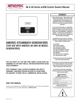
Wall Mounting:
1. Note the location of the mounting holes on the
back of the generator. The screws must set directly
into studs or equivalent supports.
Floor Mounting:
1. The generator must be restrained from moving.
Normally the piping will provide adequate support. If
not, additional support must be provided.
2. All floor installed generators must have provision
for routine draining of the tank.
SECTION 3: MOUNTING THE GENERATOR
DIAGRAM 1
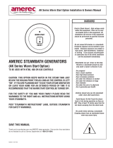
SECTION 4: STEAMHEAD INSTALLATION
WARNING
1.The steamhead mounts through a 2" hole in the
Acrylic Shower Enclosure. The steamhead should be
mounted a minimum of 12" from the floor or 6" above
a tub rim in a location where it will not present a scald
hazard to the bather in their normal seated position.
2. A 1/2" male threaded fitting should be centered to
align with the 2" diameter hole in the enclosure and
be stubbed out 1-1/2" behind the finished inside
surface of the shower enclosure. The steamhead
housing mounts to a 1"x1/2" slip to threaded PVC
fitting provided.
Test the steamhead fit prior to applying PVC
adhesive to permanently attach the steamhead
housing and slip fitting. Some play in the fit is
available by controlling how tight the slip fitting is
attached to either the steamhead housing or 1/2"
male threaded fitting, (if required the slip fitting may
also be cut shorter). Apply silicone adhesive to the
back of the steamhead housing to seal the enclosure
once the fit is verified.
(see diagrams 2,3,& 4)

page 4
4211-123 10-15-08
AV Series Installation and Service Instructions
2 "
DIAM-
ETER
HOLE
S
P
A
C
E
R
S
T
U
D
1/2" NPT
SWEAT
ADAPTER
*MALE
THREADED
FITTING
1/4"
MIN. 6" FROM
TOP OF TUB
2"
DIAMETER HOLE
1/2" NPT MALE
THREADED FITTING
LEAVE 1-1/2"
GAP FROM
END OF 1/2"
NPT FITTING
TO FINISHED
INSIDE
SURFACE OF
SHOWER
ENCLOSURE
MIN. 12"
FROM FLOOR
18 TO 22 AWG WIRE
(SOLID REQUIRED) RATED
300V, 75°C FROM GEN-
ERATOR TO CONTROL.
STRIP LENGTH = 1/4".
(NOT SUPPLIED)
DIAGRAM 2 DIAGRAM 3
DIAGRAM 5
PRINTED CIRCUIT ASSEMBLY
IN GENERATOR
WIRES MUST
BE ROUTED TO
CORRESPONDING
TERMINALS 1, 2
AND 3
R30i CONTROL
PRESS ON
ORANGE TAB
INSERT WIRE
SPECIFICATIONS
MAX. CAPACITY AVAILABLE MODEL DIMENSIONS DRY WEIGHT FILLED PACKAGED
RATING SIZES NUMBER LxWxH WEIGHT WITH WATER SHIPPING WEIGHT
80 Cubic Ft 2kW AV2 9-1/4” x 4”x 7-1/2” 2.5 lbs. 3 lbs. 3 lbs.
(1.1 kg) (1.4 kg) (1.4 kg)
DIAGRAM 4
**
* MUST ALIGN WITH 2" STEAM OUTLET HOLE IN ACRYLIC ENCLOSURE
*CENTER IN
OPENING
STEAM
STEAMHEAD
HOUSING
EYEBALL
EYEBALL
RETAINER
1/2" MALE
THREADED
1" X 1/2"
SLIP TO THREADED
PVC FITTING

page 5
4211-123 10-15-08
AV Series Installation and Service Instructions
03
SECTION 5: PLUMBING INSTRUCTIONS
Do not connect the overpressure
device output into the steam line.
Do not connect the drain valve into the
steam line.
Do not put a shut off valve in the steam
line. Avoid traps and valleys where
water could collect and cause a steam
blockage. The hot steam line must be
insulated against user contact.
Centering the steam pipe is critical in
rooms made of plastic, acrylic, resin,
fiberglass or similar materials.
Allowing the steam pipe to touch
materials not rated 212°F or higher
will result in damage to these
materials.
Do not install the steam head near
bench(es) or where steam may spray
or where condensation will drip on
the user as this will present a scald
hazard.
The steam pipe entry and any other
entry into the steam room must be
caulked to avoid damage caused by
steam leakage into the wall.
Draining the tank into the steam room
may present a scald hazard and/or
damage materials used to construct
the steam room.
Electrical shock hazard - Disconnect
all electrical power before servicing
the generator. All wiring should be
installed by a licensed electrical
contractor in accordance with local
and national codes.
Electrical Shock Hazard! Wire the
timer exactly as described. Do not
connect any additional wiring or
power supplies to the timer or timer
terminals in the generator.
Plumbing Instructions and Cautionary Notes on Installation
Minerals in the water or poor water quality can shorten the life of the steam generator or cause er-
ratic operation if the tank is not drained regularly. Drain the tank frequently.
Guard against possible contact with hot steam pipes and other plumbing.
Maximum run of the steam pipe is 12 feet. The steam pipe should be insulated. This will reduce
condensation in the steam line and will increase efficiency. Use copper and brass pipe and fittings,
1/2 inch minimum, or 3/4” silicone hose with protective cover.
Install a water supply shutoff valve where it is easily accessible.
The water supply pipe should be attached to cold supply. Do not use a saddle or piercing type
connection for the steam unit water supply.
Apply thread compound sparingly to fitting threads such that excess compound does not dis-
lodge and restrict the copper pipes or water valve. Flush lines before making connections to the
generator.
When tightening or loosening fittings, always use a backup wrench to hold the adjacent fitting.
Caution: Do not install any valves or create restrictions in the steam line. Do not construct any
dips or valleys in the steam line as condensation will accumulate in these and block the pipe
with water. Pitch the steam line such that condensation will run to the steam generator (prefer-
able) or to the steam head.
Electrical Requirements
The AV operates at 115 VAC at 50 or 60 Hz. Circuit is to be single phase 3-wire (one conductor at line voltage,
one neutral conductor and one ground conductor must be provided). Check your local building code for
requirements.Note that the line cord from the AV is equipped with a plug designed for a 20 AMP receptacle;
do not modify the plug in any way. A 20 AMP dedicated receptacle and wiring must be furnished for a proper
installation.
Caution: Without proper grounding protection, a system malfunction may cause fatal shock.
Mater
WARNING
SECTION 6: ELECTRICAL REQUIREMENTS
IMPORTANT
Maximum recommend input water pressure not to
exceed 100 PSI

page 6
4211-123 10-15-08
AV Series Installation and Service Instructions
1. Control cable rough-in:
The low voltage control can be mounted up to 75 feet from the generator
either inside or outside the steam room. (A 25’ cable is provided.) . String (3)
18 to 22 AWG solid wires from the control location through 1/2" holes in the
wall studs or ceiling joists to the generator.
Note: 1) Do not staple through or damage wires, 2) Label or
color code wires for proper TB1 to control orientation.
See diagram.
2. Control cable at the generator
Route control wires through the generator CONTROL WIRING ENTRY and
appropriate strain relief. Connect 3 wires to terminal block TB-1 on the printed
circuit assembly, as shown in diagram.
3. Install generator control (R30i)
The low voltage control can be mounted directly to a finished wall either inside
or outside the steam room. Using a 1-3/4" hole saw, drill a hole in the finished
wall where the control is to be mounted (the control wires should already be
roughed-in to this location). Locate the control wires, pull them out through
the 1-3/4" hole and plug the 3 wires into the connector on the back of the
control housing, as shown in diagram. Run a bead of 100% silicone caulk
around the perimeter on the back of the control housing. See diagram. Insert
the control into the wall cavity.
To prepare steam generator:
1. Make certain that power is disconnected.
Remove cover.
2. Feed wire through hole A and connect to
TB1 on the circuit board.
3. Locate strain relief bushing 4" from
stripped end of cable jacket with the two
connectors. Snap strain relief bushing B
into hole A.
4. Replace cover.
TB1
BLACK (3)
RED (2)
WHITE (1)
BLACK (3)
RED (2)
WHITE (1)
BUSHING B
Low voltage control wire
(25') is provided for 5 volt
DC switch connection to
steam generator.
No additional electrical
supply or wiring required.
HOLE A
A. STEAM CONTROL BY 30 MINUTE LOW VOLTAGE ON/OFF CONTROL.
SECTION 7: CONTROL INSTALLATION
THIS LOW VOLTAGE CONTROL CAN
BE LOCATED INSIDE OR OUTSIDE
THE STEAM ENCLOSURE

page 7
4211-123 10-15-08
AV Series Installation and Service Instructions
03
SECTION 8: SERVICE
Description of SteamPro Steam Generator
The AV series generator is the latest in modern steam generator design. The AV steam generator uses a printed circuit assembly to monitor and control all the equipment
needed to produce steam. The system has three functions: a timer that controls the length of the steam bath; the operating water level is monitored and controlled;
and the heating element is protected by a minimum water level sensor. The element can be removed by removing the tank and unscrewing the element.
Maintenance of SteamPro Generators
Maintenance of the AV generator includes flushing the unit periodically and visually inspecting for water leaks. Whenever the generator is opened all wiring should
be inspected for any signs of overheating. All electrical connections should be checked for tightness.
Repair of SteamPro Generators
A. ELEMENT REPLACEMENT: Disconnect power from the unit. Drain the tank. Open the front ACCESS cover.
Note the wire connections. See diagram. Loosen the tank and remove the element wires. Using a hot water
element socket, remove the element. To install a new element, clean the element port and add a light coat of
Rectorseal No. 5 pipe thread compound to the element threads. Insert and hand tighten the element. Notice the
element end orientation as shown in diagram. Tighten the element until the orientation is the same as diagram, ±
15°. Reconnect the wiring. Test the unit. Check for leaks at the element. Replace the front cover.
B. PRINTED CIRCUIT REPLACEMENT: Disconnect power from the unit. Remove the front cover. Note where the
blue wire is connected to the water level probes. Disconnect the wires from the water level probe. Disconnect the
two black wires from the water solenoid and (3) wires connected to TB1. Note and tag the position of all wires that
plug into the printed circuit assembly (PCA) mounted relays. Remove and label all the wires from the relays. When
removing these wires pull on the connector and not the wire. Four screws through the right side of the unit hold the
board in place. Remove all four screws. The printed circuit assembly can now be removed. To install the board
reverse this procedure. Test the unit.
IMPORTANT
The blue wire connected to "L" on the PCA must be connected
to the highest of the level probes.

page 8
4211-123 10-15-08
AV Series Installation and Service Instructions
C. WATER SOLENOID REPLACEMENT: Disconnect power from the unit. Turn the water supply OFF. Disconnect
the water supply from the water solenoid valve. Remove the front cover. Remove the two black wires from the
water solenoid valve. Use pliers to carefully twist the hose clamp to loosen, then slide it down the hose. Remove
the two 1/4" - 20 hex head bolts and lock washers that attach the valve to the chassis. Pull the valve off the rubber
fill hose. To install the valve, reverse these instructions. Test the unit.
D. LEVEL PROBE REPLACEMENT: Disconnect power from the unit. Remove the front cover. Note where the blue
wire is connected to the water level probe. Disconnect the wire from the water level probe. Using a 7/16” box
wrench, remove the level probe. Install a new level probe. Place a small amount of thread seal on the top threads
of the level probe.Tighten until the bottom of the plastic nut is against the top of the tank. Reattach the wire. Test
the unit.
IMPORTANT
The blue wire connected to “L” on the PCA must be connected
to the highest of the level probes.
IMPORTANT
The level probe may be extremely tight. Damage to the insulation or chassis may result unless the tank is properly blocked or sup-
ported during probe removal or installation. It may be necessary to completely disconnect and disassemble the generator.
SECTION 8: SERVICE (continued)

page 9
4211-123 10-15-08
AV Series Installation and Service Instructions
03
There are no user serviceable parts in the Generator. All repair should be performed by a qualified service person. For additional assistance or the factory
authorized service person nearest you call the Service Department at 1-800-331-0349. The Trouble Shooting Guide below is meant as a general aid only. Follow
ACTION TO BE TAKEN in order until the problem is resolved. Where replacements or repairs are indicated, see the appropriate paragraph of SERVICE SECTION.
SYMPTOMS PROBABLE CAUSES ACTION TO BE TAKEN
“Control won’t turn “”ON””
(Control light off).” “Improper power supplied (no power).
Control improperly conntected.
“”PCA”” printed circuit assembly is faulty.
Control cable is faulty.
Contol is faulty.” “1. a. Make sure circuit breaker is
“”ON””.
b. Using a voltmeter, check the voltage across the two relays on the
“”PCA””
printed circuit assembly. Voltage should be 115V.
c. Check fuse on the PCA. If fuse is blown, replace with Buss#
MDL 63MA or equivalent fuse. If the fuse blows again - call
Service Department.
2. Check control installed per instructions.
3. Replace PCA printed circuit assembly - call Service Department.
4. Replace control cable - call Service Department.
5. Replace the control - call Service Department.
“
“Control “”OFF””. (Control light off) Water won’t shut off and runs out
of the steam head.” “Water solenoid valve is stuck open.
“”PCA”” printed circuit assembly is faulty.” “1. Turn off power to the
generator. If the water stops, go to step 3.
2. a. Remove the water solenoid valve, dissassemble, clean,
re-assemble, and check for proper operation.
b. Replace valve - call Service Department.
3. Replace the “”PCA”” printed circuit assembly - call Service Depart-
ment. “
“Control “”ON””. (Control light on) Water won’t shut off and runs out
of the steam head.” “””PCA”” printed circuit assembly is
faulty.
Connection between the blue wire and the water level probe is faulty.
Unit improperly grounded.
Unit not level.” “1. Check that the blue wire is properly attached to the
water level probe. 2. Check
that the generator is properly grounded.
3. Make sure unit is mounted level.
4. Check the green ground wire to the “”PCA”” printed circuit assem-
bly.
5. Replace the “”PCA”” printed circuit assembly - call the Service De-
partment.
“
“Control “”ON”” (Control light on), Tank drained.
Unit won’t fill.” “No water supplied (turned off?)
Plugged water solenoid valve.
Water solenoid valve is faulty.
“”PCA”” printed circuit assembly is faulty.
Level probe is faulty.” “1. Check for proper water supply (Sup-
ply valve “”on””). Check for closed drain.
2. Remove the blue wire from the level probe. If the unit fills, clean or
replace the
level probe.
3. Reconnect the blue wire to the level probe. At the water valve sole-
noid, slide
back the wire connectors enough to get the voltmeter probes on the
solenoid
terminals. Measure the voltage across the solenoid terminals. If it is
not 115V
replace the printed circuit assembly. If 115V is found proceed
with steps 4 & 5.
4. Remove water solenoid valve; disassemble, clean, reassemble, and
check for
proper operation.
SMOTPMYSSESUACELBABORPNEKATEBOTNOITCA
t'nowlortnoC
"NO"nrut
thgillortnoC(
.)ffo
on(deilppusrewopreporpmI
.)rewop
.detcetnnocylreporpmilortnoC
ylbm
essatiucricdetnirp"ACP"
.ytluafsi
.ytluafsielbaclortnoC
.ytluafsilotnoC
."NO"sirekaerbtiucricerusekaM.a.1
"ACP"ehtnosyalerowtehtssorcaegatlovehtkcehc,retemtlovagnisU.b
.V511ebdluohsegatloV.ylbmessatiucricdetn
irp
#ssuBhtiwecalper,nwolbsiesuffI.ACPehtnoesufkcehC.c
llac-niagaswolbesufehtfI.esuftnelaviuqeroAM36LDM
.tnemtrapeDecivreS
.snoitcurtsnirepdellatsnilortnockcehC.2
.tnemtrapeDecivreSllac-ylbmessatiucricdetnir
pACPecalpeR.3
.tnemtrapeDecivreSllac-elbaclortnocecalpeR.4
.tnemtrapeDecivreSllac-lortnocehtecalpeR.5
."
FFO"lortnoC
)ffothgillortnoC(
tuhst'nowretaW
tuosnurdnaffo
maetsehtfo
.daeh
kcutssievlavdionelosretaW
.nepo
y
lbmessatiucricdetnirp"ACP"
.ytluafsi
.3petsotog,spotsretawehtfI.rotarenegehtotrewopffonruT.1
,naelc,elbm
essassid,evlavdionelosretawehtevomeR.a.2
.noitareporeporprofkcehcdna,elbmessa-er
.tnemtrapeDecivreSllac
-evlavecalpeR.b
.tnemtrapeDecivreSllac-ylbmessatiucricdetnirp"ACP"ehtecalpeR.3
."NO"lortnoC
thgillortnoC
(
t'nowretaW)no
snurdnaffotuhs
maetsehtfotuo
.daeh
ylbmessatiucricdetnirp"ACP"
.ytluafsi
eulbehtneewtebnoitc
ennoC
eborplevelretawehtdnaeriw
.ytluafsi
.dednuorgylreporpmitinU
.leveltontinU
.eborplevelretawehtotdehca
ttaylreporpsieriweulbehttahtkcehC.1
.dednuorgylreporpsirotarenegehttahtkcehC.2
.leveldetnuomsitinueruse
kaM.3
.ylbmessatiucricdetnirp"ACP"ehtoteriwdnuorgneergehtkcehC.4
.tnemtrapeDecivreSehtllac-ylbmessatiuc
ricdetnirp"ACP"ehtecalpeR.5
"NO"lortnoC
thgillortnoC(
knaT,)no
.deniard
.llift'nowtinU
)?ffodenrut(deilppus
retawoN
.evlavdionelosretawdeggulP
.ytluafsievlavdionelosretaW
ylbmessatiucricdetnirp"ACP"
.ytluafsi
.ytlu
afsieborpleveL
.niarddesolcrofkcehC.)"no"evlavylppuS(ylppusretawreporprofkcehC.1
ehtecalperronaelc,slli
ftinuehtfI.eborplevelehtmorferiweulbehtevomeR.2
.eborplevel
edils,dionelosevlavretawehttA.eborpleveleht
oteriweulbehttcennoceR.3
dionelosehtnoseborpretemtlovehttegothguonesrotcennoceriwehtkcab
V511tonsitifI.
slanimretdionelosehtssorcaegatlovehterusaeM.slanimret
deecorpdnuofsiV511fI.ylbmessatiucricdetnirpehtec
alper
.5&4spetshtiw
rofkcehcdna,elbmessaer,naelc,elbmessasid;evlavdionelosretawevomeR.4
.noitareporeporp
.tnemtrapeDecivreSllac-evlavdionelosretawehtecalpeR.5
SECTION 9: SERVICE

page 10
4211-123 10-15-08
AV Series Installation and Service Instructions
SMOTPMYSSESUACELBABORPNEKATEBOTNOITCA
."NO"lortnoC
)nothgillortnoC(
.maetst'nowtinU
.yletelpmocdelliftonsahtinU
.tuotnrubtnemelegnitaeH
.ytluafe
borpleveL
siylbmessatiucricdetnirp"ACP"
.ytluaf
.eborpwoLnosieriwetihwdnaeborphgiHnosieriweulbtahtkcehC.
1
."FFO"lortnocehthsuP.a.2
.yletelpmocniardotknatgniwollagulpniardehtevomeR.b
.gulpniardehtecalpeR.c
."NO
"lortnocehthsuP.d
retfasdnoces5nihtiW.esionkcilcarofnetsil,gnillifnigeblliwtinU.e
ehtetacidnilliwsihT.f
fotuhslliwllifretaweht,draehsiesionkcilc
:SMOTPMYSeeS-lliftonseodknatehtfi,3petsotoG.llufsiknat
."pulli
ft'nowtinU"
ehtdnuorgyliraropmet,draehtonsawkcilcyalerehttubdellifknatehtfI.3
ehtecalper,dednuorgsiebor
psadraehsikcilcehtfI.eborpwol/eriwetihw
tiucricdetnirp"ACP"ehtecalperdraehtonsikcilcehtfI.eborplevel
.y
lbmessa
esionkcilcehtdnadellifsahknatehttahtdenimretedneebsahtiretfA.4
yalers'eriwtnemeleehttaegatloveh
tkcehcotretemtlovaesu,draehsaw
ehtllacdnuofsiegatlovreporpfI.V511ebdluohsegatloveht-snoitcennoc
gniriwk
cehc-dnuofsiegatlovonfI.stnemelegnitaehtnemcalperrofyrotcaf
.tnemrapeDecivreSllac-margaid
nrutt'nowlort
noC
"FFO"
.)ffothgillortnoC(
.ytluafsilortnoC .tnemtrapeDecivreSllac-lortnocehtecalpeR.1
"FFO"lortnoC
.ffot
uhst'nowtinU
siylbmessatiucricdetnirp"ACP"
.ytluaf
llac-ylbmessatiucricdetnirpecalper,rotarenegehtotrewo
pehtffonruT.1
.tnemtrapeDecivreS
yllaunitnocretaW
maetsfotuosrettups
.daeh
.retawehtnistnanimatnocgnimaoF.s
emit3knathsulF.1
.tnemtrapeDecivreSllaC.2
SECTION 10: TROUBLESHOOTING

page 11
4211-123 10-15-08
AV Series Installation and Service Instructions
03
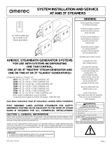
F1 1/16 A SLO-BLO
60
0
JP1
H
L
G
12
TB1
3
HIGH
PROBE
GROUND AT
MOUNTING TAB
LOW
PROBE
WHITE
BLUE
GREEN
ELEMENT
WATER
VALVE
GROUND
ON
OFF
POWER IN
NEUTRAL
120VAC
3
2
3
0
-
0
1
4124-14
01/09/02
TOP TANK
SECTION 10: WIRING DIAGRAM
/