Page is loading ...

User Guide
MTP AV Series
Twisted Pair
Video and Audio Twisted Pair
Transmitters and Receivers
68-732-01 Rev. J
04 13

Safety Instructions • English
WARNING: This symbol, , when used on the product, is intended to
alert the user of the presence of uninsulated dangerous voltage within
the product’s enclosure that may present a risk of electric shock.
ATTENTION: This symbol, , when used on the product, is intended
to alert the user of important operating and maintenance (servicing)
instructions in the literature provided with the equipment.
For information on safety guidelines, regulatory compliances, EMI/EMF
compatibility, accessibility, and related topics, see the Extron Safety and
Regulatory Compliance Guide, part number 68-290-01, on the Extron
website, www.extron.com
.
Instructions de sécurité • Français
AVERTISSEMENT: Ce pictogramme, , lorsqu’il est utilisé sur
le produit, signale à l’utilisateur la présence à l’intérieur du boîtier
du produit d’une tension électrique dangereuse susceptible de
provoquer un choc électrique.
ATTENTION: Ce pictogramme, , lorsqu’il est utilisé sur le produit,
signale à l’utilisateur des instructions d’utilisation ou de maintenance
importantes qui se trouvent dans la documentation fournie avec le
matériel.
Pour en savoir plus sur les règles de sécurité, la conformité à la
réglementation, la compatibilité EMI/EMF, l’accessibilité, et autres sujets
connexes, lisez les informations de sécurité et de conformité Extron, réf. 68-
290-01, sur le site Extron, www.extron.fr.
Sicherheitsanweisungen • Deutsch
WARNUNG: Dieses Symbol auf dem Produkt soll den Benutzer
darauf aufmerksam machen, dass im Inneren des Gehäuses dieses
Produktes gefährliche Spannungen herrschen, die nicht isoliert sind
und die einen elektrischen Schlag verursachen können.
VORSICHT: Dieses Symbol auf dem Produkt soll dem Benutzer in
der im Lieferumfang enthaltenen Dokumentation besonders wichtige
Hinweise zur Bedienung und Wartung (Instandhaltung) geben.
Weitere Informationen über die Sicherheitsrichtlinien, Produkthandhabung,
EMI/EMF-Kompatibilität, Zugänglichkeit und verwandte Themen finden Sie
in den Extron-Richtlinien für Sicherheit und Handhabung (Artikelnummer 68-
290-01) auf der Extron-Website, www.extron.de.
Instrucciones de seguridad • Español
ADVERTENCIA: Este símbolo, , cuando se utiliza en el producto,
avisa al usuario de la presencia de voltaje peligroso sin aislar dentro del
producto, lo que puede representar un riesgo de descarga eléctrica.
ATENCIÓN: Este símbolo, , cuando se utiliza en el producto, avisa
al usuario de la presencia de importantes instrucciones de uso y
mantenimiento recogidas en la documentación proporcionada con
el equipo.
Para obtener información sobre directrices de seguridad, cumplimiento
de normativas, compatibilidad electromagnética, accesibilidad y temas
relacionados, consulte la Guía de cumplimiento de normativas y seguridad
de Extron, referencia 68-290-01, en el sitio Web de Extron, www.extron.es
.
Chinese Simplified(简体中文)
警告: 产品上的这个标志意在警告用户该产品机壳内有暴露的危险
电 压 ,有 触 电 危 险 。
注意: 产品上的这个标志意在提示用户设备随附的用户手册中有
重要的操作和维护(维修)说明。
关于我们产品的安全指南、遵循的规范、
EMI/EMF 的兼容性、无障碍
使用的特性等相关内容,敬请访问
Extron 网站 www.extron.cn,参见 Extron
安全规范指南,产品编号
68-290-01。
Chinese Traditional(繁體中文)
警告: 若產品上使用此符號,是為了提醒使用者,產品機殼內存在著
可能會導致觸電之風險的未絕緣危險電壓。
注意 若產品上使用此符號,是為了提醒使用者。
有關安全性指導方針、法規遵守、EMI/EMF 相容性、存取範圍和相關主題的詳細
資訊,請瀏覽 Extron 網站:www.extron.cn,然後參閱《Extron 安全性與法規
遵守手冊》,準則編號 68-290-01。
Japanese
警告: この記号 が製品上に表示されている場合は、筐体内に絶縁されて
いない高電圧が流れ、感電の危険があることを示しています。
注意:この記号 が製品上に表示されている場合は、本機の取扱説明書に
記載されている重要な操作と保守(整備)の指示についてユーザーの
注意を喚起するものです。
安全上のご注意、法規厳守、EMI/EMF適合性、その他の関連項目に
つ い て は 、エ ク スト ロ ン の ウ ェブ サ イト www.extron.jpより
『Extron Safety and Regulatory Compliance Guide』 (P/N 68-290-01) をご覧ください。
Korean
경고: 이 기호 , 가 제품에 사용될 경우, 제품의 인클로저 내에 있는
접지되지 않은 위험한 전류로 인해 사용자가 감전될 위험이 있음을
경고합니다.
주의: 이 기호 , 가 제품에 사용될 경우, 장비와 함께 제공된 책자에 나와
있는 주요 운영 및 유지보수(정비) 지침을 경고합니다.
안전 가이드라인, 규제 준수, EMI/EMF 호환성, 접근성, 그리고 관련
항목에 대한 자세한 내용은 Extron 웹 사이트(www.extron.com)의
Extron 안전 및 규제 준수 안내서, 68-290-01 조항을 참조하십시오.

FCC Class A Notice
This equipment has been tested and found to comply with the limits for a Class A digital
device, pursuant to part15 of the FCC rules. The ClassA limits provide reasonable
protection against harmful interference when the equipment is operated in a commercial
environment. This equipment generates, uses, and can radiate radio frequency energy and,
if not installed and used in accordance with the instruction manual, may cause harmful
interference to radio communications. Operation of this equipment in a residential area is
likely to cause interference; the user must correct the interference at his own expense.
NOTE: This unit was tested with shielded I/O cables on the peripheral devices. Shielded
cables must be used to ensure compliance with FCC emissions limits.
For more information on safety guidelines, regulatory compliances, EMI/EMF
compatibility, accessibility, and related topics, see the “Extron Safety and Regulatory
Compliance Guide” on the Extron website.
Copyright
© 2013 Extron Electronics. All rights reserved.
Trademarks
All trademarks mentioned in this guide are the properties of their respective owners.
The following registered trademarks
(R)
, registered service marks
(SM)
, and trademarks
(TM)
are the property of
RGBSystems, Inc. or Extron Electronics:
Registered Trademarks
(®)
AVTrac, Cable Cubby, CrossPoint, eBUS, EDID Manager, EDID Minder, Extron, Flat Field,GlobalViewer, Hideaway, Inline, IP Intercom, IP Link, Key Minder, LockIt, MediaLink, PoleVault,
PowerCage, PURE3, Quantum, SoundField, System Integrator, TouchLink, V-Lock, VersaTools, VN-Matrix, VoiceLift, WallVault, WindoWall
Registered Service Mark
(SM)
: S3 Service Support Solutions
Trademarks
(
™
)
AAP, AFL (Accu-Rate Frame Lock), ADSP (Advanced Digital Sync Processing), AIS (Advanced Instruction Set), Auto-Image, CDRS (Class D Ripple Suppression), DDSP (Digital Display
Sync Processing), DMI (Dynamic Motion Interpolation), Driver Configurator, DSP Configurator, DSVP (Digital Sync Validation Processing), FastBite, FOXBOX, IP Intercom HelpDesk, MAAP,
MicroDigital, ProDSP, QS-FPC (QuickSwitch Front Panel Controller), Scope-Trigger, SIS, Simple Instruction Set, Skew-Free, SpeedMount, SpeedNav, SpeedSwitch, Triple-Action Switching,
XTP, XTP Systems, XTRA, ZipCaddy, ZipClip

Conventions Used in this Guide
Notifications
The following notifications are used in this guide:
CAUTION: Electrical Shock that may result in injury. Use tools with care to
prevent injury.
ATTENTION: Attention indicates a situation that may damage or destroy the product or
associated equipment.
NOTE: A note draws attention to important information.
TIP: A tip provides a suggestion to make working with the application easier.
Software Commands
Commands are written in the fonts shown here:
^AR Merge Scene,,Op1 scene 1,1 ^B 51 ^W^C
[01] R 0004 00300 00400 00800 00600 [02] 35 [17] [03]
E X! *X1&* X2)* X2#* X2! CE}
NOTE: For commands and examples of computer or device responses mentioned
in this guide, the character “0” is used for the number zero and “O” represents the
capital letter “o.”
Computer responses and directory paths that do not have variables are written in the font
shown here:
Reply from 208.132.180.48: bytes=32 times=2ms TTL=32
C:\Program Files\Extron
Variables are written in slanted form as shown here:
ping xxx.xxx.xxx.xxx —t
SOH R Data STX Command ETB ETX
Selectable items, such as menu names, menu options, buttons, tabs, and field names are
written in the font shown here:
From the File menu, select New.
Click the OK button.
Specifications Availability
Product specification are available on the Extron website, www.extron.com.

Contents
Introduction .................................................... 1
About the MTP Transmitters and Receivers ........ 1
TP Cable Advantages ......................................... 2
Transmission Distance ........................................ 2
Installation ...................................................... 3
Signal Jumpers for Generational Compatibility .... 3
Setting the Jumpers on New Generation
NonAAP Models ........................................... 4
Setting the Jumpers on AAP Transmitters ....... 6
Panel Features and Connections ........................ 7
Transmitter Input Connections ........................ 7
Transmitter and Receiver Throughput
Connections .................................................. 9
Power Connection (All Models) ..................... 11
Receiver Output Connections ....................... 12
Operation ...................................................... 14
Front Panel Features ......................................... 14
Troubleshooting — Skew Delay Compensation . 14
Reference Information ................................. 15
Mounting Options ............................................. 15
UL Requirements
.......................................... 15
Tabletop Use (All Except AAP Models) .......... 15
Frame Mounting (AAP Models)
..................... 16
MTP AV Series • Contents iv

MTP AV Series • Contents v

MTP AV Series • Introduction 1
Introduction
This section introduces the MTP transmitters and receivers. Topics discussed in this section
are:
• About the MTP Transmitters and Receivers
• TP Cable Advantages
• Transmission Distance
About the MTP Transmitters and Receivers
The Extron MTP transmitters and receivers provide a system for long-distance distribution
of NTSC, PAL, or SECAM video and audio. The MTPs transmit and receive over the
Extron Enhanced Skew-Free AV UTP cable, Category (CAT) 5 shielded twisted pair (STP),
unshielded twisted pair (UTP), or foil shielded twisted pair (FTP) cable.
The MTPs are a part of the Extron line of basic distribution amplifiers, switchers,
transmitters, receivers, and associated video accessories.
The MTP transmitters input and the receivers output S-video (luminance [Y] and
chrominance[C]) or composite video.
Audio input is either balanced or unbalanced audio on captive screw connectors as well
as unbalanced audio on RCA connectors. The transmitters sum the left and right audio
channels to convert the audio to mono (L+R) format.
NOTE: MTPs can be configured for stereo audio output.
The MTP transmitter then converts the input video and mono audio signals (if applicable)
to proprietary signals and outputs them to the compatible MTP receiver on an RJ-45
connector.
Each transmitter requires a compatible receiver. The table on page 2 shows the video and
audio capabilities of each model, the transmitter and receiver compatibility, and Architectural
Adapter Plate (AAP) mountability.
The MTPs ship with external desktop 12 V power supplies that accept 100 to 240 VAC,
50-60 Hz input. If jumpers are repositioned from the default settings, a single power supply
can power both units if there is less than 200 feet (61 meters) of STP/UTP/FTP cable
between the two.

MTP AV Series • Introduction 2
TP Cable Advantages
Twisted pair (TP) cable is much smaller, lighter, more flexible, and less expensive than coaxial
cable. These TP products make cable runs simpler and less cumbersome. Termination of
the cable with RJ-45 connectors is simple, quick, and economical.
Transmitters
MTP Series Features
S-Video
Composite
Video
Audio
(Captive
Screw)
Audio
(RCA)
AAP
Mounted
MTP T SV A • •
MTP T SV A RCA • •
MTP T AV • •
MTP T AV RCA • •
MTP T AV AAP • • •
Receivers
MTP R SV A • •
MTP R SV A RCA • •
MTP R AV • •
MTP R AV A RCA • •
Transmission Distance
Extron suggests a minimum transmission distance of at least 50 feet. The maximum
transmission distance when using Enhanced Skew-Free AV UTP cable or UTP CAT 5 cable,
terminated with CAT 5 rated connectors, is 1000 feet.
NOTES:
• It is possible to exceed the recommended distance, however, image quality may be
reduced.
• The transmitters and receivers are designed for and perform best with Extron
Enhanced Skew-Free AV cable. CAT 5 cables are acceptable, but are less
preferable. We also recommend the use of preterminated and tested cables when
possible. Cables terminated on site should be tested before use to ensure that they
comply with Category 5 specifications.
• The video portion of any S-video output by the transmitter is compatible with any
S-video receiver in the MTP family described in this guide if the transmitter and
receiver jumper configuration are compatible.
• The video portion of any composite video output by the transmitter is compatible
with any composite video receiver in the MTP family described in this guide if the
transmitter and receiver jumper configuration are compatible.
• The audio output of any transmitter (captive screw or RCA) is compatible with
any audio receiver in the MTP family described in this guide if the transmitter and
receiver jumper configuration are compatible.

MTP AV Series • Installation 3
Installation
This section describes the installation procedures, including:
• Signal Jumpers for Generational Compatibility
• Panel Features and Connections
CAUTION: Installation and service must be performed by authorized personnel only.
Signal Jumpers for Generational Compatibility
Over time, the MTPs have been redesigned, affecting the signal content of the TP cable wire
pairs, changing the audio from stereo to mono, and eliminating the remote power capability.
The new-generation units are not compatible with the old generation unless an internal
jumper in the new unit is shifted.
Shift the jumpers for the new transmitter, receiver, or both if:
• Your installation mixes a transmitter and receiver from different generations.
• You want the units to transmit stereo audio.
• You want one unit to remotely power another.
Use the table below to identify the generation (revision level) of the transmitter and receiver
in your installation. If any of the above scenarios are true, reconfigure the jumpers for the
units before mounting the units.
NOTE: Only the new generation units have these jumpers.
Transmitter
Old Generation
Part Number
New Generation
Part Number
MTP T SV A 60-540-22 60-540-52
MTP T SV A RCA 60-540-32 60-540-62
MTP T AV 60-540-21 60-540-51
MTP T AV RCA 60-540-31 60-540-61
MTP T AV AAP 70-361-02, -03 70-361-22
Receiver
Old Generation
Part Number
New Generation
Part Number
MTP R SV A 60-541-22 60-541-52
MTP R SV A RCA 60-541-32 60-541-62
MTP R AV 60-541-21 60-541-51
MTP R AV RCA 60-541-31 60-541-61

MTP AV Series • Installation 4
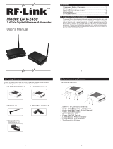
Setting the Jumpers on New Generation NonAAP Models
1. Remove and retain the four screws (two on each side of the unit) that secure the cover
to the MTP (see figure 1).
SHARP
GAIN
Figure1. Removing the MTP Cover
2. For the receiver, slide the cover slightly forward to clear the front panel adjustment
knobs.
3. Lift the cover straight up.
4. Remove and retain the two screws that secure the audio board to the main (video)
board (see figure 2).
5. Pull the audio board back until the audio connectors clear the back of the unit and lift
the board out of the way.
Transmitter Front Panel Receiver Front Panel
Receiver Rear PanelTransmitter Rear Panel
Remove and retain these screws.
Figure2. Removing the Audio Board

MTP AV Series • Installation 5
6. Locate the jumper blocks (see figure 3) on the video board. Shift the jumper to the
alternate location.
Transmitter Front Panel Receiver Front Panel
Receiver Rear PanelTransmitter
Rear Panel
Mono (default jumper position)
Compatible with new model transmitter/receivers.
Cannot remotely power transmitter/receiver.
Stereo
Compatible with old model transmitter/receivers.
Can remotely power transmitter/receiver.
Figure3. Video Board Jumper Locations
7. Reinstall the audio board and secure it in place with the screws (removed in step 4).
8. For the receiver, locate the jumper block on the audio board (see figure 4). Shift the
jumper to the alternate location.
Receiver Rear Panel
Mono (default jumper position)
Compatible with new model transmitters.
Mono audio.
Cannot remotely power transmitter
Stereo
Compatible with old model transmitters.
Stereo audio.
Can remotely power transmitter.
Receiver Front Panel
Figure4. Receiver Audio Board Jumper Locations
NOTES:
• The jumper locations and functions are the same whether the receiver is
equipped with captive screw or RCA audio connectors.
• Both jumpers (video and audio) must be set to either mono or stereo for it to
pass audio and video successfully.
9. Replace the cover and the four screws (removed in step 1).

MTP AV Series • Installation 6
Setting the Jumpers on AAP Transmitters
1. Remove and retain the two screws that secure the back cover to the MTP (see figure 5).
12V
0.5A MAX
OUTPUT
POWER
− +
1. Remove these Screws 2. Carefully pull the RJ-45 connector
through this hole.
Figure5. Removing the MTP Cover
2. Pull the cover out of the way, carefully twisting the RJ-45 connector as necessary to
slide it through the hole in the cover marked “Output.”
3. Remove and retain the two standoffs that secure the audio board to the main (video)
board (see figure 6). Lift the audio board out of the way.
Remove these standoffs.
Figure6. Removing the Audio Board
4. Locate the jumper block (see figure 7) on the video board. Shift the jumper to the
alternate location.
Mono (default jumper position)
Compatible with new model receivers.
Cannot remotely power receiver
Stereo
Compatible with old model receivers.
Can remotely power receiver.
Figure7. Video Board Jumper Locations
5. Replace the audio board and secure it in place with the standoffs (removed in step 3).
6. Feed the RJ-45 connector through the hole in the cover marked “Output” and replace
the cover. Secure the cover in place with the two screws (removed in step 1).
ATTENTION: Ensure that the TP cable is not pinched when you reinstall the cover.

MTP AV Series • Installation 7
Panel Features and Connections
Transmitter Input Connections
Figure 8 shows all of the combinations of video and audio input connectors that you may
encounter with your MTP transmitter.
12V
0.5a
INPUT
MTP T AV RCA
OUTPUT
MAX
VIDEO
LR
INPUT
LR
12V
0.5a
MTP T AV
OUTPUT
MAX
VIDEO
12V
0.5a
INPUT
LR
MTP T SV A
OUTPUT
MAX
S-VIDEO
12V
0.5a
INPUT
MTP T SV A RCA
OUTPUT
MAX
S-VIDEO
LR
MTP T SV A RCA,
Rear Panel
MTP T AV RCA,
Rear Panel
MTP T AV AAP,
Front Panel
MTP T SV A,
Rear Panel
MTP T AV,
Rear Panel
AUDIO IN
VIDEO
IN
LR
MTP T AV
21
21
4
4
L
2
3
3
4
Figure8. Video and Audio Input Connections
a
S-video connector (SV models) —
Connect an S-video input to this 4-pin mini DIN
connector.
b Composite video connector
(AV models)
— Connect a composite video input to this
connector (female RCA on the MTP T AV AAP, female BNC on all other models).
c Audio input captive screw connector (MTP T SV A, MTP T AV) — Connect a
balanced or unbalanced audio input to this 3.5 mm, 5-pole captive screw connector.
Connectors are included with each MTP, but you must supply the audio cable. See
figure9 to wire a connector for the appropriate input type. Use the supplied tie-wrap to
secure the audio cable to the extended tail of the connector.
NOTE: High impedance is generally over 800 ohms.
Unbalanced Stereo Input
Do not tin the wires!
Tip
Sleeve
Sleeve
Tip
LR
Balanced Stereo Input
Tip
Ring
Tip
Ring
LR
Sleeves
Figure9. Captive Screw Input Connector Wiring

MTP AV Series • Installation 8
CAUTIONS:
• The length of the exposed (stripped) portion of the copper wires is important.
The ideal length is 3/16 inches (5 mm). Longer bare wires can short together.
Shorter bare wires are not as secure in the direct insertion connectors and
could be pulled out.
• The captive screw audio connector can easily be inadvertently plugged
partially into one receptacle and partially into an adjacent receptacle. This
misconnection could damage the audio output circuits. Ensure that the
connector is plugged fully and only into the desired input or output.
NOTES:
• When making connections for the MTP using existing audio cables, see
figure 10 to identify the tip, ring, and sleeve wires in various connectors.
• A mono audio connector consists of the tip and sleeve.
• A stereo audio connector consists of the tip, ring, and sleeve.
• The ring, tip, and sleeve wires are also shown on the captive screw audio
connector diagrams (see figure 9 and figure 17).
Tip (+)
Sleeve ( )
RCA Connector (Mono)
Sleeve ( )
Ring (R)
Tip (L)
3.5 mm Stereo Plug Connector
(unbalanced)
Figure10. Typical Audio Connectors
d
Audio input RCA connectors (RCA and AAP models) —
Connect an unbalanced
stereo audio source to these L(eft) and R(ight) RCA connectors (see figure 11).
Sleeve (Gnd )
Right Channel
(Red Jacket)
Left Channel
(White Jacket)
Tip (Signal)
Figure11. RCA Audio Connectors

MTP AV Series • Installation 9
Transmitter and Receiver Throughput Connections
Figure 12 identifies the connections between the transmitter and receiver.
12V
0.5A MAX
OUTPUT
POWER
− +
MTP Transmitters MTP Receivers
INPUT
LR
MTP T AV
OUTPUT
VIDEO
12V
0.5a
INPUT
MTP T SV A RCA
OUTPUT
MAX
12V
0.5a
MAX
S-VIDEO
LR
OUTPUT
MTP R SV A RCA
INPUT
S-VIDEO
12V
0.5a MAX
OUTPUT
MTP R AV
LR
INPUT
VIDEO
12V
0.5a MAX
R
L
1 1
1
Figure12. Throughput Connections
ATTENTION: Do not connect these devices to a computer data network or a
telecommunications network.
NOTE: RJ-45 termination must comply with the TIA/EIA T 568A or TIA/EIA T 568B
wiring standards for all connections (see figure 13).
a Transmitter output and receiver input connector — Connect one end of a TP cable
to this RJ-45 female connector on the transmitter. On the MTPTAV AAP, the connector
is at the end of a short pigtail.
Connect the free end of the same TP cable from the transmitter to the RJ-45 female
connector on the receiver.

MTP AV Series • Installation 10
TP cable termination
Figure 13 details the recommended termination of TP cables with RJ-45 connectors in
accordance with the TIA/EIA T 568A or TIA/EIA T 568B wiring standards. You can use either
standard, but ensure that you use the same standard on both cable ends.
ATTENTION: Damage may occur to the unit if TP cables are miswired as crossover
cables.
12345678
RJ-45
Connector
Insert Twisted
Pair Wires
Pins:
Figure13.TP Cable Termination
NOTES:
• Enhanced Skew-Free AV cable is not recommended for Ethernet/LAN
applications.
• This cable is specially designed for compatibility with Extron Twisted Pair products,
wired using the TIA/EIA 568 A standard.
• The green, brown, and blue pairs of this cable have virtually identical lengths and
should be used to transmit the video signals.
• The orange pair of this cable has a different length and should not be used to
transmit the video signals.
Crossover Cable Straight-through Cable
Pin End 1
Wire Color
End 2
Wire Color
Pin End 1
Wire Color
End 2
Wire Color
1 White-green White-orange 1 White-orange White-orange
2 Green Orange 2 Orange Orange
3 White-orange White-green 3 White-green White-green
4 Blue Blue 4 Blue Blue
5 White-blue White-blue 5 White-blue White-blue
6 Orange Green 6 Green Green
7 White-brown White-brown 7 White-brown White-brown
8 Brown Brown 8 Brown Brown
T658A T568B T568B T568B
A cable that is wired as T568A at one end and
T568B at the other (Tx and Rx pairs reversed)
is a “crossover” cable.
A cable wired the same at both ends is called
a “straight-through” cable, because no
pin/pair assignments are swapped.

MTP AV Series • Installation 11
Power Connection (All Models)
See figure 14 to identify the power connections, indicators, and panel screws.
MTP Transmitter
sM
TP Receivers
MTP AAP Transmitters
INPUT
MTP T SV A RCA
OUTPUT
S-VIDEO
LR
OUTPUT
MTP R SV A RCA
INPUT
S-VIDEO
R
L
12V
0.5a
MAX
12V
0.5a MAX
AUDIO IN
VIDEO
IN
LR
MTP T AV
12V
0.5A MAX
OUTPUT
POWER
− +
1
2
1
1
2 2
Figure14. Power Connections and Indicators
a Power connector — Plug the external 12 VDC power supply into this 2-pole captive
screw connector on both the transmitter and the receiver. Figure 15 shows how to wire
the connector.
Power Supply
Output Cord
Captive Screw Connector
SECTION A–A
Ridges
Smooth
AA
Tie Wrap
5
Figure15. Power Connector Wiring
CAUTION: The two power cord wires must be kept separate while the power
supply is plugged in. Remove power before wiring.
NOTES:
• If the transmitter and receiver are either older generation units or jumper
configured to the stereo audio position (compatible with the older units), only a
single device needs to be powered in a two-unit system (see “Signal Jumpers
for Generational Compatibility” on page 3). The device connected to the
power supply, in turn, provides power to its counterpart. This remote power
application is only available in stereo mode, not mono mode.
• If the transmitter and receiver are separated by more than 200 feet (61meters)
of STP/UTP/FTP cable, connect a power supply to both units.
• Do not tin the stripped power supply leads before installing the captive screw
or direct insertion connector. Tinned wires could be pulled out because they are
not as secure in the captive screw and direct insertion connectors.

MTP AV Series • Installation 12
ATTENTION:
• Power supply voltage polarity is critical. Incorrect voltage polarity can damage the
power supply and the MTP. Identify the power cord negative lead by the ridges on
the side of the cord (see
figure 15).
• The length of the exposed (stripped) copper wires is important. The ideal length
is 3/16 inches (5 mm). Longer bare wires can short together. Shorter wires are
not as secure in the captive screw connectors and could be pulled out.
To verify the polarity before connection, plug in the power supply with no load and
check the output with a voltmeter.
Use the supplied tie-wrap to strap the power cord to the extended tail of the connector.
NOTES:
• Your transmitter/receiver pair may have shipped with a blue captive screw
connector. This blue connector can be plugged into either a blue or an orange
power receptacle.
• The blue connector does not have an extended tail or the included tie-wrap.
Alternatively, an optional Extron PS 124 Universal 12 VDC Power Supply (part number
60-1022-01) can power multiple Extron 12 VDC devices using only one AC power
connector.
b Power LED — Indicates power is applied to the MTP.
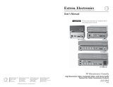
Receiver Output Connections
See figure 16 to identify the rear panel output connections of the receivers. The figure shows
all of the combinations of connectors that you may encounter with your MTP receiver.
MTP R AV RCA,
Rear Panel
MTP R AV,
Rear Panel
MTP R SV A RCA,
Rear Panel
MTP R SV A,
Rear Panel
OUTPUT
MTP R AV RCA
INPUT
VIDEO
12V
0.5a MAX
L R
OUTPUT
MTP R SV A
L R
INPUT
S-VIDEO
12V
0.5a MAX
OUTPUT
MTP R SV A RCA
INPUT
S-VIDEO
12V
0.5a MAX
L
R
OUTPUT
MTP R AV
L R
INPUT
VIDEO
12V
0.5a MAX
2 2
3
4
1 1
3
4
Figure16. Output Connector Wiring
a
S-video connector (SV models) —
Connect an S-video device to this 4-pin mini DIN
connector.
b Composite video connector (AV models) — Connect a composite video device to
this BNC connector.

MTP AV Series • Installation 13
c Captive screw audio connector (MTP R SV A, MTP R AV) — Connect a balanced
or unbalanced audio device, such as an audio amplifier, to this 3.5 mm, 5-pole captive
screw connector (see figure 17 to properly wire the output connector).
Do not tin the wires!
Balanced Audio Output
Tip
Ring
Tip
Ring
LR
Sleeves
Unbalanced Audio Output
Tip
No Ground Here
No Ground Here
Tip
LR
Sleeves
Figure17. Captive Screw Connector Wiring for Audio Output
ATTENTION:
• Connect the sleeve to ground ( ). Connecting the sleeve to a negative (-)
terminal will damage the audio output circuits.
• The length of the exposed (stripped) portion of the copper wires is important.
The ideal length is 3/16 inches (5 mm). Longer bare wires can short together.
Shorter bare wires are not as secure in the direct insertion connectors and
could be pulled out.
d RCA audio connectors (RCA models) — Connect a stereo audio device to these
L(eft) and R(ight) RCA connectors.

MTP AV Series • Operation 14
Operation
This section describes:
• Front Panel Features
• Troubleshooting — Skew Delay Compensation
Front Panel Features
SHARP
C GAIN
Y GAIN
SHARP
GAIN
MTP R S-video Receiver
Front Panel
MTP R Composite Video
Receiver Front Panel
2331231
Figure18. MTP Receiver Front Panels
a Power LED — When lit, this LED indicates power is applied to the MTP.
b Sharpness — Adjusts the output image sharpness for long cable runs.
c Gain control — Adjusts the brightness of the output image to compensate for long
cable runs.
Composite video receivers — There is only one gain control on composite video MTP
receivers.
S-video receivers — There are separate controls for luminance (Y) and
chrominance(C) on S-video MTP receivers. If the S-video output chrominance setting
on the MTP receiver is too low, the image may appear in monochrome. Adjust the
chrominance (C gain) until color appears.
NOTE: All control knobs are removable to limit access if desired.
Troubleshooting — Skew Delay Compensation
CAT 5 TP cable can cause registration errors (in which luminance leads or lags
chrominance) between the Y and C video signals on S-video transmitter/receiver pairs. Try
using the following methods to minimize or eliminate pair skew:
• Switch to Extron Enhanced Skew-Free AV UTP cable.
• Add an S-video-to-BNC adapter and a skew compensation cable equal to the length of
pair skew to the receiver output.
• Install an S-video-to-BNC adapter and an SEQ 100 15HD Skew Equalizer on the
receiver video output and adjust the skew for the leading video image.
/