Page is loading ...

User’s Guide
Extron Electronics, USA
1230 South Lewis Street
Anaheim, CA 92805
USA
714.491.1500
Fax 714.491.1517
Extron Electronics, Europe
Beeldschermweg 6C
3821 AH Amersfoort
The Netherlands
+31.33.453.4040
Fax +31.33.453.4050
Extron Electronics, Asia
135 Joo Seng Road, #04-01
PM Industrial Building
Singapore 368363
+65.6383.4400
Fax +65.6383.4664
Extron Electronics, Japan
Daisan DMJ Building 6F
3-9-1 Kudan Minami
Chiyoda-ku, Tokyo 102-0074 Japan
+81.3.3511.7655
Fax +81.3.3511.7656
www.extron.com
© 2002 Extron Electronics. All rights reserved.
CAT 6 Patch Cable and Coaxial Skew Cables
68-600-01 Rev. B
Printed in the USA
03 02
CAT 6 Install Kit

CAT 6 Install Kit • Equalizing Pair SkewCAT 6 Install Kit • Cable Testing
Overview
32
The Extron CAT 6 Installation Kits include a pretested, plenum or
non-plenum, Category 6 (CAT 6) patch cable and whatever
coaxial skew cables are necessary to correct measured pair skew.
The CAT 6 cable is preterminated with RJ-45 plug connectors.
The coaxial skew cable is color coded (red, green, or blue jacket)
and is preterminated with BNC connectors.
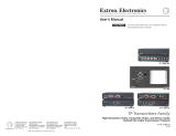
Termination of CAT 6 Cable
Figure 1 details how the CAT 6 cables in the Installation Kits are
terminated in accordance with the TIA/EIA T 568A wiring
standards.
Clip DownSide
1
1&2
3&6 4&5
7&8
2345678
12345678
Pin Wire color
RGB video and audio
Signal Level
1 White-green Red/V. sync+ ±0.35V
2 Green Red/V. sync- ±0.35V
3 White-orange
Audio &
power
+15V with
±0.5 V
4 Blue Green+ +0.35V
5 White-blue Green- -0.35V
6 Orange
Audio &
power
±0.5 V
7 White-brown Blue/H. sync+ ±0.35V
8 Brown Blue/H. sync- ±0.35V
RJ-45 connector
Twisted Pairs
Figure 1 — CAT 6 cable termination
Cable Testing
To ensure proper cable termination, each transmission cable sold
as part of an Installation Kit is tested from end to end to give an
accurate indication of cable quality.
A complete test measures cable length and tests the wire map,
attenuation, NEXT, PSNEXT, ELFEXT, PSELFEXT, return loss,
ACR, and PSARC. All of these tests are critical for digital data
transfer. While all of these tests are important indicators of the
quality of the cable termination, the most critical testing
parameters for video transfer are wire map (T-568-A termination)
and pair length measurements. The largest concern is
equalization of skew between cable pairs. Cable systems of 300
feet or less should exhibit no transmission problems if they pass
CAT 6-D5 channel certification testing.
Equalizing Pair Skew
The manufacturing process for CAT 6 cable leads to a condition
called pair skew. Skew exists between pairs when the physical
length of one wire pair is different from another. As the
transmission cable length increases, the amount of skew
increases. Skew affects the displayed image when the differential
length between wire pairs exceeds 2 feet, causing the timing of
the red, green, and blue video signals to appear out of alignment
(horizontal registration errors). A white vertical line on a black
field can appear as individual red, green, and blue lines that are
close together; the signal transmitted on the shortest wire pair
leads the other colors and appears to the left on the display.
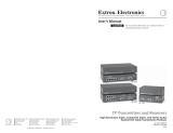
CAT 6 cable test equipment measures and reports wire pair
length. The report on the various pair lengths can be used in
equalizing pair skew. The nominal velocity of propagation (NVP
— the speed at which the signal travels on the transmission line,
measured as a percentage of the speed of light) of CAT 6 cable is
very close to that of conventional coaxial cable. The similarity in
NVP means that an additional length of coax equal to the length
of pair skew, placed on the receiver’s output, equalizes the effects
of pair skew (figure 2).
The installation kit includes skew compensation cable(s) that
compensate(s) for the level of skew observed in testing at Extron.
TP T 15HD A
TP R BNC A
T
P
T
1
5
H
D
A
H
-
S
H
I
F
T
B
U
F
F
E
R
E
D
C
O
M
P
U
T
E
R
I
N
P
U
T
A
U
D
I
O
ID PIN 4
ID PIN 11
L
O
C
A
L
M
O
N
I
T
O
R
PC Computer
CAT 6 Cable
Audio
LCD Projector
... THEN insert a four foot
extension cable to equalize
TP skew for red video.
IF cable measurement
indicates that the pair
with wires
1 and 2
is
four feet shorter than
the other pairs...
RGB INPUT
RGB
OUTPUT
R
G
B
H/HV
V
A
AU
DIO
L
R
B
SOG
C SYNC
P
O
W
E
R
1
5
V
.
5
A
D
C
L
R
Pair RGB video
1, 2 Red
4, 5 Green
7, 8 Blue
Figure 2 — Pair skew equalization
/