Page is loading ...

ULTRAFLO
®
Dead End Fill System
For additional parts and information, contact your nearest Chore-Time distributor or representative.
Find your nearest distributor at: www.choretime.com/contacts
MC1190BMay 2018
Installation and Operators Manual
Installation and Operators Manual

Limited Warranty ULTRAFLO® Dead End Fill System
2
MC1190B
LIMITED WARRANTY
Chore-Time Group, a division of CTB, Inc. (“Chore-Time”) warrants the new CHORE-TIME ULTRAFLO
®
components
manufactured by Chore-Time to be free from defects in material or workmanship under normal usage and conditions, for
One (1) year from the date of installation by the original purchaser (“Warranty”). Chore-Time provides for an extension of
the aforementioned Warranty period (“Extended Warranty Period”) with respect to certain Product parts. If such a defect is
determined by Chore-Time to exist within the applicable period, Chore-Time will, at its option, (a) repair the Product or
Component Part free of charge, F.O.B. the factory of manufacture or (b) replace the Product or Component Part free of
charge, F.O.B. the factory of manufacture. This Warranty is not transferable, and applies only to the original purchaser of
the Product.
CONDITIONS AND LIMITATIONS
THIS WARRANTY CONSTITUTES CHORE-TIME’S ENTIRE AND SOLE WARRANTY AND CHORE-TIME
EXPRESSLY DISCLAIMS ANY AND ALL OTHER WARRANTIES, INCLUDING, BUT NOT LIMITED TO,
EXPRESS AND IMPLIED WARRANTIES, INCLUDING, WIHTOUT LIMITATION, WARRANTIES AS TO
MERCHANTABILITY OR FITNESS FOR PARTICULAR PURPOSES. CHORE-TIME shall not be liable for any direct,
indirect, incidental, consequential or special damages which any purchaser may suffer or claim to suffer as a result of any
defect in the Product. Consequential or Special Damages as used herein include, but are not limited to, lost or damaged
products or goods, costs of transportation, lost sales, lost orders, lost income, increased overhead, labor and incidental costs,
and operational inefficiencies. Some jurisdictions prohibit limitations on implied warranties and/or the exclusion or
limitation of such damages, so these limitations and exclusions may not apply to you. This warranty gives the original
purchaser specific legal rights. You may also have other rights based upon your specific jurisdiction.
Compliance with federal, state and local rules which apply to the location, installation and use of the Product are the
responsibility of the original purchaser, and CHORE-TIME shall not be liable for any damages which may result from non-
compliance with such rules.
The following circumstances shall render this Warranty void:
· Modifications made to the Product not specifically delineated in the Product manual.
· Product not installed and/or operated in accordance with the instructions published by the CHORE-TIME.
· All components of the Product are not original equipment supplied by CHORE-TIME.
· Product was not purchased from and/or installed by a CHORE-TIME authorized distributor or certified
representative.
· Product experienced malfunction or failure resulting from misuse, abuse, mismanagement, negligence, alteration,
accident, or lack of proper maintenance, or from lightning strikes, electrical power surges or interruption of
electricity.
· Product experienced corrosion, material deterioration and/or equipment malfunction caused by or consistent with
the application of chemicals, minerals, sediments or other foreign elements.
· Product was used for any purpose other than for the care of poultry and livestock.
·
The Warranty and Extended Warranty may only be modified in writing by an officer of CHORE-TIME. CHORE-TIME
shall have no obligation or responsibility for any representations or warranties made by or on behalf of any distributor,
dealer, agent or certified representative.
Limited Warranty
Effective: April 2014

Contents
Topic Page
MC1190B
3
Limited Warranty. . . . . . . . . . . . . . . . . . . . . . . . . . . . . . . . . . . . . . . . . . . . . . . . . . . . . . . . . . . . . . . . 2
Support Information . . . . . . . . . . . . . . . . . . . . . . . . . . . . . . . . . . . . . . . . . . . . . . . . . . . . . . . . . . . . . 4
Safety and General Information . . . . . . . . . . . . . . . . . . . . . . . . . . . . . . . . . . . . . . . . . . . . . . . . . . . . 5
Follow Safety Instructions . . . . . . . . . . . . . . . . . . . . . . . . . . . . . . . . . . . . . . . . . . . . . . . . . . . . . . . . . . . . . . 5
Decal Descriptions . . . . . . . . . . . . . . . . . . . . . . . . . . . . . . . . . . . . . . . . . . . . . . . . . . . . . . . . . . . . . . . . . . . . 5
DANGER: Moving Parts . . . . . . . . . . . . . . . . . . . . . . . . . . . . . . . . . . . . . . . . . . . . . . . . . . . . . . . . . . . 5
DANGER: Electrical Hazard . . . . . . . . . . . . . . . . . . . . . . . . . . . . . . . . . . . . . . . . . . . . . . . . . . . . . . . . 5
General and Planning Information. . . . . . . . . . . . . . . . . . . . . . . . . . . . . . . . . . . . . . . . . . . . . . . . . . 6
Installation. . . . . . . . . . . . . . . . . . . . . . . . . . . . . . . . . . . . . . . . . . . . . . . . . . . . . . . . . . . . . . . . . . . . . . 7
Dead End Fill System Installation . . . . . . . . . . . . . . . . . . . . . . . . . . . . . . . . . . . . . . . . . . . . . . . . . . . . . . . . 7
Feed Manifold Installation. . . . . . . . . . . . . . . . . . . . . . . . . . . . . . . . . . . . . . . . . . . . . . . . . . . . . . . . . . . 7
Fill System Installation . . . . . . . . . . . . . . . . . . . . . . . . . . . . . . . . . . . . . . . . . . . . . . . . . . . . . . . . . . . . . 7
Drop Tube Installation for Single Fill Systems . . . . . . . . . . . . . . . . . . . . . . . . . . . . . . . . . . . . . . . . . . . 8
Switch Installation . . . . . . . . . . . . . . . . . . . . . . . . . . . . . . . . . . . . . . . . . . . . . . . . . . . . . . . . . . . . . . . . . 8
Drop Installation for Twin Systems (Model 90 & 108) . . . . . . . . . . . . . . . . . . . . . . . . . . . . . . . . . . . . 9
Fill System Installation (Outside the Building) . . . . . . . . . . . . . . . . . . . . . . . . . . . . . . . . . . . . . . . . . . .10
Wiring . . . . . . . . . . . . . . . . . . . . . . . . . . . . . . . . . . . . . . . . . . . . . . . . . . . . . . . . . . . . . . . . . . . . . . . . 11
Single Phase Wiring for all systems except Model 108 Two Motor Tandem (w/o Starters) . . . . . . . . . . . .11
Single Phase Wiring for Model 108 Two Motor Tandem (w/o Starters) . . . . . . . . . . . . . . . . . . . . . . . . . . .12
Single Phase Wiring for all Systems Except Model 108 (With Starters) . . . . . . . . . . . . . . . . . . . . . . . . . . .13
3 Phase Wiring for all Systems (With Starters) . . . . . . . . . . . . . . . . . . . . . . . . . . . . . . . . . . . . . . . . . . . . . .14
Parts Listing . . . . . . . . . . . . . . . . . . . . . . . . . . . . . . . . . . . . . . . . . . . . . . . . . . . . . . . . . . . . . . . . . . . 15
Feed Manifold Part Numbers . . . . . . . . . . . . . . . . . . . . . . . . . . . . . . . . . . . . . . . . . . . . . . . . . . . . . . . . . . . .15
MMB, MMBBG, Versa, Versa II, Versa Plus Cages . . . . . . . . . . . . . . . . . . . . . . . . . . . . . . . . . . . . . .15
DURA, DURAKO, DURA-STEP,DURA II, BG Curtain Back, BG Stacked, BG 2+2, BG DBS, and BG ST
Cages. . . . . . . . . . . . . . . . . . . . . . . . . . . . . . . . . . . . . . . . . . . . . . . . . . . . . . . . . . . . . . . . . . . . . . . . . . . . . . . . .16

Support Information ULTRAFLO® Dead End Fill System
4
MC1190B
The ULTRAFLO Dead End Fill System is designed to convey poultry
feed types. Using this equipment for any other purpose or in a way not
within the operating recommendations specified in this manual will void
the warranty and may cause personal injury and/or death.
This manual is designed to provide comprehensive planning, installation,
wiring, operation, and parts listing information. The Table of Contents
provides a convenient overview of the information in this manual. The
Table of Contents also specifies which pages contain information for the
sales personal, installer, and consumer (end user).
IMPORTANT: CE stands for certified Europe. It is a standard which
equipment must meet or exceed in order to be sold in Europe. CE provides
a benchmark for safety and manufacturing issues. CE is required only on
equipment sold in Europe.
Chore-Time Equipment recognizes CE Mark and pursues compliance in
all applicable products. Please fill in the CE-Mark serial number in the
blank space provided for future reference.
Please include the name and address of your Chore-Time Distributor and
installer.
Support Information
(CE-mark serial number)
Please fill in the following information about your ULTRAFLO Dead End Fill System. Keep this
manual in a clean, dry place for future reference.
Distributor’s Name
Distributor’s Address
Distributor’s Phone Date of Purchase
Installer’s Name
Installer’s Address
Installer’s Phone Date of Installation
System Specifications
Feed Delivery System Supplying

ULTRAFLO® Dead End Fill System Safety and General Information
5
MC1190B
Caution, Warning and Danger Decals have been placed on the equipment to warn of potentially dangerous
situations. Care should be taken to keep this information intact and easy to read at all times. Replace missing or
damaged safety decals immediately.
Safety–Alert Symbol
This is a safety–alert symbol. When you see this symbol on your equipment, be alert to the potential
for personal injury. This equipment is designed to be installed and operated as safely as
possible...however, hazards do exist.
Understanding Signal Words
Signal words are used in conjunction with the safety–alert symbol to identify the severity of the warning.
DANGER indicates an imminently hazardous situation which, if not avoided, WILL result in death or
serious injury.
WARNING indicates a potentially hazardous situation which, if not avoided, COULD result in death or
serious injury.
CAUTION indicates a hazardous situation which, if not avoided, MAY result in minor or moderate
injury.
Follow Safety Instructions
Carefully read all safety messages in this manual and on your equipment safety signs. Follow recommended
precautions and safe operating practices.
Keep safety signs in good condition. Replace missing or damaged safety signs.
Decal Descriptions
DANGER: Moving Parts
Disconnect electrical power before working on system,
equipment may start automatically. Otherwise personal injury
will result.
Severe personal injury will result if the equipment is operated
without covers properly installed.
DANGER: Electrical Hazard
Disconnect electrical power before inspecting or servicing equipment unless
maintenance instructions specifically state otherwise.
Ground all electrical equipment for safety.
All electrical wiring must be done by a qualified electrician in accordance with
local and national electric codes.
Ground all non-current carrying metal parts to guard against electrical shock.
Electrical disconnects and over current protection are not supplied with the
equipment.
Safety and General Information

General and Planning Information ULTRAFLO® Dead End Fill System
6
MC1190B
Thank you for purchasing a CHORE-TIME Dead End Fill System.
Carefully read all the instructions prior to beginning the installation.
White rust is caused by moisture trapped between galvanized parts. If moisture is present, separate parts and allow
for good air circulation.
CHORE-TIME fill systems and feeding systems are designed to handle most common poultry feeds. However,
we cannot guarantee satisfactory operation with all rations. We suggest you contact the CHORE-TIME Technical
Service Department concerning the use of new or unusual formulations.
The Dead End Fill System is used to supply the ULTRAFLO Feeding System with feed. The ULTRAFLO
Feeding System Installation Manual (MC656) is included with the Intake Cups and covers the feeding system
installation process.
The Dead End Fill System is used to deliver feed from the feed bins to the ULTRAFLO Cage Feeder as required.
The Dead End Fill System is designed for tier feeding applications only. Row feeding applications require use of
the ULTRAFLO Loop Fill System. See the ULTRAFLO Loop Fill System Installation Manual (MC1191).
The Dead End Fill System may be a Model 90, Twin Model 90, Model 108, or Hi-Speed Model 108, depending
on the capacity required (number of ULTRAFLO Feeder Lines to be supplied). Twin Model 108 Dead End Fill
Systems are also available for split-ration applications only.
The chart below shows the delivery capacities of the various Dead End Fill Systems available.
Related Instruction Manuals
General and Planning Information
Systems
Pounds/
Minute
Pounds/
Hour
Kg./
Minute
Kg./
Hour
# of Lines
Supplied
Model 90 100 6,000 45 2,700 4
Twin
Model 90
200 12,000 90 5,400 8
Model 108 220 13,200 98 5,800 8
Hi-Speed
Model 108
250 15,000 113 6804 8
Related Instruction Manuals Inst. No.
Two Motor Tandem System Manual (Model 90) MA524
Two Motor Tandem System Manual (Model 108) MA1101
Model 55, 75, 90, & HMC FLEX-AUGER Fill System Manual MA1000
Model 108 FLEX-AUGER Fill System Manual MA1032
Dual Model 90 Control Unit MA1277
Dual Model 108 Control Unit MA1064
Model 90, 108, & Dual 90 Feed Screener Manual MC1033
ULTRAFLO Feeding System Manual MC656
Note: Some of the instructions listed above are available in various languages. Contact your CHORE-
TIME Distributor for additional manuals.

ULTRAFLO® Dead End Fill System Installation
7
MC1190B
Dead End Fill System Installation
Feed Manifold Installation
1.The Intake Cups should be installed according to the ULTRAFLO Feeding System Installation Instructions
(MC656).
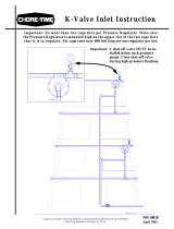
2.Install the Feed Manifolds with the drop-outs in the Intake Cups, as shown in Figure 1.
3.Slide the Feed Manifolds down into the Intake Cups 3/4” (19 mm) to 1” (25 mm).
Fill System Installation
Install the inside portion of the Fill System according to the appropriate Fill System Installation Manual
(MA1702 for Model 90 Fill Systems, MA1714 for Model 108 Fill Systems, MA1712 for Model 90 & Model
108 Screeners).
NOTE:CAREFUL PLANNING IS REQUIRED. Make sure that the inside and outside portions of the Fill
System are going to match up prior to beginning to install the equipment.
The Control Unit must be located directly over the Feed Manifold farthest from the Feed Bin.
An Outlet Drop must be located directly above each Feed Manifold. If possible do not install an Outlet Drop on
or just before an elbow. If the Outlet Drop MUST be installed on or just before an elbow, reduce the size of the
outlet hole to provide some feed bypass to cushion the auger.
The Fill System should be suspended approximately 12” (31 cm) above the Feed Manifolds.
Installation
Figure 1.Feed Manifold Installation
1
Item Description
1Feed Manifold
2 Intake Cup
3 3/4"-1" [19-25MM]
2
3

Installation ULTRAFLO® Dead End Fill System
8
MC1190B
Drop Tube Installation for Single Fill Systems
Cut the Drop Tubes to length and assemble on to the bottom of the Outlet Drop. (See Figure 2.)
The Drop Tubes should extend down into the top of the Feed Manifolds approximately 2” (50 mm) as shown.
Model 90 and Twin 90: Secure the Drop Tube onto the Outlet Drop using the Hose Clamp supplied.
Model 108: Secure the Drop Tube onto the Outlet Drop using the self-tapping screws supplied.
Switch Installation
The Proximity Level Switch Assembly is designed to provide reliable feed sensing in confinement poultry
applications.
The ULTRAFLO version of the Proximity Level Switch does not include any switching relays or contactors and
is intended to switch only control circuitry (not motor current).
The Switch is used to start and stop the Fill System during a feeding cycle.
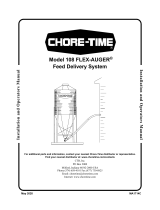
Figure 3 shows a Proximity Level Switch installed. Refer to the Installation Instructions (MA1713) shipped
with the Proximity Level Switch for detailed installation and wiring information.
Figure 2.Drop Tube Installation (Single Fill Systems)
Item Description
1 Outlet Tube (Model 108 shown)
2 Self-Tapping Screw (Note: Model 90 uses a
Hose Clamp in place of Self Tapping Screw.
3 Drop Tube
4 Feed Manifold
5 Intake Cup
6 2" [50mm]
2
3
4
1
5
6
Item Description
1 Dead End Fill System Control Unit
2 Proximity Switch
3 Control Unit Drop Assembly
4 Drop Tube
5 Hose Clamp
1
2
3
4
5
Figure 3.Switch Installation


Installation ULTRAFLO® Dead End Fill System
10
MC1190B
Fill System Installation (Outside the Building)
Install the outside portion of the Fill System according to the appropriate Fill System Installation Manual
(MA1702 for Model 90, MA1714 for Model 108) (See Figure 5.)
If a Feed Screener is to be used, refer to the Feed Screener Installation Manual (MC1033) for planning and
installation information.
NOTE:CAREFUL PLANNING IS REQUIRED. Make sure that the inside and outside portions of the Fill
System are going to match up prior to beginning to install the equipment.
If it is necessary to cut an elbow, refer to Figure 5. Always measure along the outside radius of the elbow when
determining cut location. Use an abrasive cut-off saw to cut the hardened steel elbows.
Figure 5.Fill System Installation
Figure 6.Cutting the Elbow

ULTRAFLO® Dead End Fill System Wiring
MC1190B
11
Single Phase Wiring for all systems except Model 108 Two Motor Tandem (w/o Starters)
Wiring
Figure 7.Single Phase Wiring for all Systems except 108 Wiring Diagram (Single Phase, w/o Starters)
230 V, 50/60 Hz
1 PH Supply for Fill System
Part No. 42549
Contacter Box
Disconnect
(Not Supplied)
Fill System Motor
230V, 1PH, 2 HP, Max
Contactor needed only if Two Motor Tandem System is used. Otherwise,
connect Screener Motor to Flex-Auger Control Terminals 3 and 4.
Disconnect
(Not Supplied)
Screener Motor 230V, 1 PH,
1HP Max.
Disconnect
(Not Supplied)
Part No. 7840 Tandem Boot Switch
Cross Auger Motor
230V, 1 PH, 3/4 HP Max.
Part No. 7840
Level Switch on Feed Screener
Control Unit on
Feed Screener
Control Unit for
Fill System
This Jumper
must be added
in the field
230 V, 50/60 Hz
1 PH Supply for Fill System
Black(4)Black (3)
Black (1)
Blue
Brown
Constant 230 Volt Supply
L2 or N
L1
Ground
Wiring Inside Dashed Lines is needed
only if Two Motor Tandem System is
used.
Part No. 34255
Prox. Level Switch
Part No. 28910-0 ULTRA-
FLO Feeding Control Panel
123456
123456

ULTRAFLO® Dead End Fill System Wiring
MC1190B
12
Single Phase Wiring for Model 108 Two Motor Tandem (w/o Starters)
Figure 8.Model 108 Single Phase Model 108 Two Motor Tandem System (w/o Starters) Wiring
230 V, 50/60 Hz
1 PH Supply for Fill System
Part No. 42549
Single Contactor Box
Disconnect
(Not Supplied)
Fill System Motor
230V, 1PH, 2 HP, Max
Screener Motor
230V, 1 PH, 1HP Max.
Disconnect
(Not Supplied)
Part No. 7840 Level
Switch on Cross Auger
Cross Auger
Motor
230V, 1 PH, 3/4
HP Max.
Part No. 7840
Level Switch on Feed Screener
Control Unit on
Feed Screener
Control Unit for
Fill System
This Jumper
must be added
in the field
230 V, 50/60 Hz
1 PH Supply
Black (3)
Black (4)
Black (1)
Blue
Brown
Constant 230 Volt Supply
L2 or N
L1
Ground
Part No. 34255
Prox. Level Switch
Part No. 28910-0 ULTRAFLO
Feeding Control Panel
42549 Single Contactor Box
Disconnect (Not Supplied)
Cross Auger
Control Unit
Wiring Inside Dashed Lines is needed only
if Two Motor Tandem System is used.

ULTRAFLO® Dead End Fill System Wiring
MC1190B
13
Single Phase Wiring for all Systems Except Model 108 (With Starters)
Figure 9.Single Phase all Systems except Model 108 (Single Phase with Starters Wiring)
230 V, 50/60 Hz
1 PH Supply for
Fill System
Fill System Motor
230V, 1PH, 2 HP, Max
Screener Motor
230V, 1 PH,
1HP Max.
Cross Auger Motor
230V, 1 PH, 3/4 HP
Max.
Part No. 7840
Tandem Boot Switch
Control Unit for
Fill System
Black
Black
Black
Blue
Brown
Constant 230 Volt Supply
L2 or N
L1
Ground
Part No. 28910-0 ULTRAFLO Feeding Control Panel
L2 or N
L1
Fuses for Short Circuit Protection
(Not Supplied)
Motor Starter
(Not Supplied)
Disconnect
(Not Supplied)
Fuses for Short Circuit Protection
(Not Supplied)
230 V, 50/60 Hz
1 PH Supply for
Fill System
Motor Starter
(Not Supplied)
Motor Starter
(Not Supplied)
Disconnect
(Not Supplied)
Fuses for Short Circuit Protection
(Not Supplied)
Control Unit on
Feed Screener
Part No. 7840
Level Switch on Feed Screener
230 V, 50/60 Hz, 1 PH Supply
Part No. 34255
Prox. Level Switch
This Jumper
must be added
in the field
Disconnect
(Not Supplied)
230 V, 50/60 Hz
1 PH Supply for
Fill System
Wiring Inside Dashed Lines is needed only
if Two Motor Tandem System is used.

ULTRAFLO® Dead End Fill System Wiring
MC1190B
14
3 Phase Wiring for all Systems (With Starters)
Figure 10.3 Phase for all Systems (with Starters) Wiring
Screener Motor
3 PH, 1HP Max.
Cross Auger Motor
230V, 3PH, 1 HP Max.
Part No. 7840
Tandem Boot Switch
Control Unit for Fill System
Black (3)
Black (1)
Black (4)
Blue
Brown
Constant 230 Volt Supply
L2 or N
L1
Ground
Part No. 28910-0 ULTRAFLO Feeding Control Panel
L2
L3
Motor Starter
(Not Supplied)
Supply
Motor Starter
(Not Supplied)
Motor Starter
(Not Supplied)
Disconnect
(Not Supplied)
Fuses for Short Circuit Protection (Not Supplied)
Control Unit
on Feed
Screener
Part No. 7840
Level Switch on Feed Screener
230 V, 50/60 Hz,
1 PH Supply
Part No. 34255 Prox. Level Switch
This Jumper must be
added in the field
L1
3x 230V
3x 380V
3x 415V
3x 460V
3x 230V
3x 380V
3x 415V
3x 460V
3x 230V
3x 380V
3x 415V
3x 460V
Disconnect
(Not Supplied)
Fuses for Short Circuit Protection
(Not Supplied)
Fuses for Short Circuit Protection
(Not Supplied)
Disconnect
(Not Supplied)
L2
L3
L1
Fill System Motor
3PH, 2 HP Max.
Supply
Wiring inside dashed lines is needed only
if Two Motor Tandem is used.
L3
L2
L1

ULTRAFLO® Dead End Fill System Parts Listing
15
MC1190B
Feed Manifold Part Numbers
MMB, MMBBG, Versa, Versa II, Versa Plus Cages
Parts Listing
MMB Cages MMBBG Cages Versa, Versa II,
& Versa Plus
Item Manifold Type Number of Tiers Manifold Part Numbers
1 Combined
3 55557-3 55047 55318
4 55557-4 55048 55319
5 55557-5 55050 --
2Top
2 55559-2 -- 55315
3 55559-3 54652 55316
4 55559-4 55019 55274
5 55559-5 -- --
3 Center 3 55705-3 55052 55317
4 55705-4 -- 55273
4 Bottom
3 55558-3 54653 55272
4 55558-4 55018 55300
5 55558-5 54420 --
4
3
2
1

Parts Listing ULTRAFLO® Dead End Fill System
16
MC1190B
DURA, DURAKO, DURA-STEP,DURA II, BG Curtain Back, BG Stacked, BG 2+2, BG DBS, and BG ST Cages.
DURA-CAGE
TM
DURA-TRIM
TM
DBS
DURAKO
DURA
TM
STEP
DURA
TM
II
Brood-Grow
Curtain Back
Brood-Grow
Stacked
Brood -Grow
2+2 (14")
Brood-Grow
2+2 (15")
Brood-Grow
DBS
Brood-Grow
ST
# of Tiers Manifold Part Numbers
2 -- -- -- 25530 -- -- 25357 -- -- -- 25807
3 24850 -- -- -- 27246 -- -- -- -- -- --
4 24795 35194 35194 -- -- 24463 -- 24509 26028 25781 --
5 28570 36777 -- -- -- -- -- -- -- -- --
Manifold


MADE TO WORK.
BUILT TO LAST.
®
Revisions to this Manual
Page No. Description of Change
Various Updated Manual with new Cage Styles
Contact your nearby Chore-Time distributor or representative for additional parts and information.
Chore-Time Group
A division of CTB, Inc.
PO Box 2000
Milford, Indiana 46542-2000 USA
Phone (574) 658-4101 Fax (877) 730-8825
E-mail: www.choretimepoultry.com
Internet: poultr[email protected]
/