Page is loading ...

INSERT THE PTZ MECHANISM
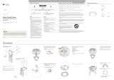
Insert the PTZ mechanism into the upper housing by
aligning the hooks of the PTZ mechanism to the hook
guides located on the housing.
INSERT THE IN-CEILING HOUSING
Fix the in-ceiling housing by turning the clip bolts located
on the housing clockwise.
6
7
8
INSERT THE IN-CEILING HOUSING
Insert the housing into the ceiling hole and press the edge
of the housing against the ceiling.
5
CLOSE THE JUNCTION BOX COVER
Close the junction box cover by attaching the junction box
hooks to the side holes on the junction box cover.
4
RS-485 Port
Protocol,
Address DIP Switch
BNC Video Port
Alarm Out
Alarm In
Power Port
Inner Box
Main Connector Port
CONNECT THE WIRES AND TERMINAL BLOCKS
Connect the cables to terminal blocks and BNC located in
the inner box of the junction box.
See “Installation - Cabling” in the next section.
2
3
DRILL THE HOLE ON THE CEILING
To install the in-ceiling housing in the ceiling, rst drill a
190mm diamter hole on the ceiling.
HOOK THE SAFETY WIRES
Connect one of the rings for the safety wire with the housing
safety wire hanger to prevent the junction box cover from
falling down. Then, connect the other ring with the hanger
bolt of the ceiling.
1
DETACH PTZ MECHANISM AND JUNCTION BOX COVER
By pressing down and holding up the hooks located on
both sides of the PTZ Mechanism, detach PTZ Mechanism
from the housing. Then, detach the junction box cover by
pressing down the hooks on both sides of the junction
box.
CD with
User’s Manual
Product Accessories
Quick Start Guide
Dome Cover
In-Ceiling Housing
with PTZ Mechanism
Safety Wire
X
2
Safety Information
Important Safety Instructions
This symbol indicates that dangerous voltage
consisting a risk of electric shock is present within
this unit.
Warning Precaution
This exclamation point symbol is intended to alert the
user to the presence of important operating and
maintenance (servicing) instructions in the literature
accompanying the appliance.
TO REDUCE THE RISK OF ELECTRIC SHOCK, DO NOT REMOVE COVER (OR BACK) NO USER SERVICEABLE
PARTS INSIDE. REFER SERVICING TO QUALIFIED SERVICE PERSONNEL.
CAUTION
:
CAUTION
RISK OF ELECTRIC SHOCK.
DO NOT OPEN.
To prevent damage which may result in fire or electric shock
hazard, do not expose this appliance to rain or moisture.
Be sure to use only the standard adapter that is specified
in the specification sheet. Using any other adapter could
cause fire, electrical shock, or damage to the product.
Incorrectly connecting the power supply or replacing
battery may cause explosion, fire, electric shock, or damage
to the product.
Do not connect multiple cameras to a single adapter.
Exceeding the capacity may cause excessive heat
generation or fire.
Securely plug the power cord into the power receptacle.
Insecure connection may cause fire.
When installing the camera, fasten it securely and firmly.
A falling camera may cause personal injury.
Do not place conductive objects (e.g. screw drivers, coins,
metal items, etc.) or containers filled with water on top of
the camera. Doing so may cause personal injury due to fire,
electric shock, or falling objects.
Do not install the unit in humid, dusty, or sooty locations.
Doing so may cause fire or electric shock.
If any unusual smells or smoke come from the unit, stop
using the product. Immediately disconnect the power
source and contact the service center. Continued use in
such a condition may cause fire or electric shock.
If this product fails to operate normally, contact the nearest
service center. Never disassemble or modify this product in
any way.
When cleaning, do not spray water directly onto parts of
the product. Doing so may cause fire or electric shock.
Warning
Warning
1.
2.
3.
4.
5.
6.
7.
8.
9.
10.
Precaution
Operating
• Before using, make sure power supply and all other parts
are properly connected.
• While operating, if any abnormal condition or malfunction
is observed, stop using the camera immediately and contact
your dealer.
Handling
• Do not disassemble or tamper with parts inside the camera.
• Do not drop the camera or subject it to shock or vibration
as this can damage the camera.
• Clean the clear dome cover with extra care. Scratches and
dust can ruin the quality of the camera image.
Installation and Storage
• Do not install the camera in areas of extreme temperature,
exceeding the allowed range.
• Avoid installing in humid or dusty environments.
• Avoid installing in places where radiation is present.
• Avoid installing in places where there are strong magnetic
• Avoid installing in places where the camera would be
subject to strong vibrations.
• Never expose the camera to rain or water.
1. Read these instructions. - All these safety and operating instructions should be read before the product is installed or operated.
2. Keep these instructions. - The safety, operating and use instructions should be retained for future reference.
3. Heed all warnings. - All warnings on the product and in the operating instructions should be adhered to.
4. Follow all instructions. - All operating and use instructions should be followed.
5. Do not use this device near water. - For example: near a bath tub, wash bowl, kitchen sink, laundry tub, in a wet basement;
near a swimming pool; etc.
6. Clean only with dry cloth. - Unplug this product from the wall outlet before cleaning. Do not use liquid cleaners.
7. Do not block any ventilation openings. Install in accordance with the manufacturer’s instructions. - Slots and openings in
the cabinet are provided for ventilation, to ensure reliable operation of the product, and to protect it from over-heating. The
openings should never be blocked by placing the product on bed, sofa, rug or other similar surface. This product should not
be placed in a built-in installation such as a bookcase or rack unless proper ventilation is provided and the manufacturer’s
unstructions have been adhere to.
8.
produce heat.
9. Do not defeat the safety purpose of the polarized or grounding-type plug. A polarized plug has two blades with one wider
than the other. A grounding type plug has two blades and a third grounding prong. The wide blade or the third prong are
obsolete outlet.
10. Protect the power cord from being walked on or pinched particularly at plugs, convenience receptacles, and the point
where they exit from the apparatus.
11.
12.
manufacturer, or sold with the apparatus. When a cart is used, use
caution when moving the cart/apparatus combination to avoid
injury from tip-over.
13. Unplug this apparatus during lightning storms or when unused for long periods of time.
14.
such as power supply cord or plug is damaged, liquid has been spilled or objects have fallen into the apparatus, the
apparatus has been exposed to rain or moisture, does not operate normally, or has been dropped.
11
10
Close the dome cover. Match the arrow mark on the
dome cover and the housing.
Tighten four screws on the dome cover in the sequence
shown in the image below.
To maintain the best sealing, the torque of each
screw must be in the range of
0.5 ~ 1.0 N·m(0.3 ~ 0.73 lbf·ft).
Arrow Mark
20150121
TEL: (866) 446-3595
www.Digital-Watchdog.com / [email protected]
Technical Support Hours: Monday-Friday 9:00AM to 8:00PM EST
Thank you for purchasing Digital Watchdog’s Super Speed Dome PTZ Outdoor Dome Camera.
Before installing the camera, please verify your model and read this guide carefully.
The following items are included with the PTZ camera
PREPARATION
x37 Analog PTZ Dome Camera
In-Ceiling FLush Mount
ATTACH THE DOME COVER
Attach the dome cover by xing the dome cover side hooks
to the edge of the housing.
DETACH THE PROTECTION VINYL
9
10
DWC-PTZ37XFM
Quick Start Guide
This equipment has been tested and found to comply with the limits for a Class A digital device, pursuant to part 15 of the FCC Rules.
These limits are designed to provide reasonable protection against harmful interference when the equipment is operated in a
commercial environment. This equipment generates, uses, and can radiate radio frequency energy and, if not installed and used in
accordance with the instruction manual, may cause harmful interference to radio communications. Operation of this equipment in a
residential area is likely to cause harmful interference in which case the user will be required to correct the interference a this own
expense.
To disconnect power from the mains, pull out the mains cord plug.
When install the product, ensure that the plug is easily accessible.
Version 1.01
INSTALLATION

Inner Box
Alarm Output
Alarm Input
Inner Box
Alarm Input/Sensor
6
5
ALARM INPUT
GND1
2 3 4 5 6 7 8
COM
In 1
In 8
Alarm Output
OUT1
OUT2
OUT3
OUT4
RS-485
(Keyboard Controller/DVR)
Video Output
Power
BNC Cable
Inner Box
1
2
3
~
~
RS-485
The schedule function allows running an appropriate function
like preset, scan, pattern, group, home move at designated
day and time.
To setup a schedule, at least 1 Preset, 1 scan, 1 pattern, and 1
group should be setup.
FUNCTION SETUP
- - - - - - - - - - - - - - - - - - - - - - - - - - -
<PRESET SETUP>
<SCAN SETUP>
<PATTERN SETUP>
<GROUP SETUP>
<SCHEDULE SETUP>
BACK
EXIT
SCHEDULE SETUP
- - - - - - - - - - - - - - - - - - - - - - - - - - -
MASTER ENABLE OFF
DAY TIME ACT NO ON
1
UNDEFINED
2 UNDEFINED
3 UNDEFINED
4 UNDEFINED
5 UNDEFINED
6 UNDEFINED
7 UNDEFINED
BACK
SCHEDULE SETUP
- - - - - - - - - - - - - - - - - - - - - - - - - - -
MASTER ENABLE OFF
DAY TIME ACT NO ON
1
ALL 00:00 HOM OFF
2 UNDEFINED
3 UNDEFINED
4 UNDEFINED
5 UNDEFINED
6 UNDEFINED
7 UNDEFINED
BACK
SCHEDULE SETUP
- - - - - - - - - - - - - - - - - - - - - - - - - - -
MASTER ENABLE ON
DAY TIME ACT NO ON
1
MON 01: 20 HOM ON
2 WED 07:00 PRS 1
2 ON
3 THU 11
:40 SCN 3 ON
4 ALL 1
2:00 SCN 1 ON
5 UNDEFINED
6 UNDEFINED
7 UNDEFINED
BACK
In the Root Menu,
go to Function Setup> Schedule Setup
Select the schedule you wish to modify, and using the
mouse’s wheel, scroll near to enter Edit mode.
Select the days of the week you wish
to set for this schedule. Select from
All, WKD (Every day except Saturday
and Sunday), or Sun~Sat. When you are
done, click on the right corner of the screen
to move to the next edit section.
Continue to edit the time of the day, the act you wish
to run at that time (home, preset, pattern, scan, group),
select the act no for a specific action. When you are
complete, to enable the schedule select ON. Using
the mouse’s wheel, scroll near to save changes or far
to cancel.
To enable the camera to start running the schedules,
make sure the specific schedule is enabled, and
also MASTER ENABLE on the top of the screen is ON.
The group function allows you to run a sequence of presets,
patterns, and/or scans. Maximum 8 groups can be stored, with
each group including a
maximum of 20 different actions.
To setup a group, setup at least 1 preset, scan and pattern.
FUNCTION SETUP
- - - - - - - - - - - - - - - - - - - - - - - - - - -
<PRESET SETUP>
<SCAN SETUP>
<PATTERN SETUP>
<GROUP SETUP>
<SCHEDULE SETUP>
BACK
EXIT
GROUP SETUP
- - - - - - - - - - - - - - - - - - - - - - - - - - -
GROUP NO.
CLEAR GROUP
<
EDIT GROUP>
BACK
EXIT
1
UNDEFINED
CANCEL
EDIT GROUP 1
- - - - - - - - - - - - - - - - - - - - - - - - - - -
NO. ACTION NO. DWELL OPT
- - - - - - - - - - - - - - - - - - - - - - - - - -
1
NONE
2 NONE
3 NONE
4 NONE
5 NONE
- - - - - - - - - - - - - - - - - - - - - - - - - -
SAVE
CANCEL
[NEAR:EDIT ACT]
[FAR :EDIT END]
[ :
MOVE CURSOR
]
[ : CHANGE VAL.]
EDIT GROUP 1
- - - - - - - - - - - - - - - - - - - - - - - - - - -
NO. ACTION NO. DWELL OPT
- - - - - - - - - - - - - - - - - - - - - - - - - -
1
NONE
2 NONE
3 NONE
4 NONE
5 NONE
- - - - - - - - - - - - - - - - - - - - - - - - - -
SAVE
CANCEL
In the Root Menu,
go to Function Setup> Group Setup
Select the Group you wish to modify. If a group
is not defined, ‘UNDEFINED’ will be displayed
as shown.
Select the first action in the group.
Click with the mouse on the right side
of the screen to enter edit mode.
Using the mouse, click on the top and bottom of the
screen to scroll down the options. Select from
Preset, Pattern, Scan. Click on the right side of the
screen to save selection and move to the next tab to
the right.
Using the mouse, continue editing the desired
information. Enter the action’s number, Dwell
time between each action, and the number of
repetitions under OPT.
[ :
MOVE CURSOR
]
[ : CHANGE VAL.]
EDIT GROUP 1
- - - - - - - - - - - - - - - - - - - - - - - - - - -
NO. ACTION NO. DWELL OPT
- - - - - - - - - - - - - - - - - - - - - - - - - -
1
PATTERN
1
00:0
3 1
2 NONE
3 NONE
4 NONE
5 NONE
- - - - - - - - - - - - - - - - - - - - - - - - - -
SAVE
CANCEL
When you finish setting up an ACTION,
press Near or Enter key to one-upper-level
menu. Move to the next action and repeat setup
as necessary. When you have completed entering
all desired actions, scroll near to save changes,
or far to cancel all changes.
EDIT GROUP 1
- - - - - - - - - - - - - - - - - - - - - - - - - - -
NO. ACTION NO. DWELL OPT
- - - - - - - - - - - - - - - - - - - - - - - - - -
1
PATTERN
1
00:0
3 1
2 NONE
3 NONE
4 NONE
5 NONE
- - - - - - - - - - - - - - - - - - - - - - - - - -
SAVE
CANCEL
[NEAR:EDIT ACT]
[FAR :EDIT END]
1st POS.
1. CW direction
2. CCW direction
2nd POS.
By using the scan function, you can make the camera move
repeatedly between
2 presets.
When the scan function runs, the camera moves between
preset 1 and preset 2 CW(Clockwise). Then the camera moves
from preset 2 back to preset 1 CCW (Counterclockwise).
Users can setup 1~8 different scans.
To setup a scan, at least two (2) presets must be setup.
FUNCTION SETUP
- - - - - - - - - - - - - - - - - - - - - - - - - - -
<PRESET SETUP>
<SCAN SETUP>
<PATTERN SETUP>
<GROUP SETUP>
<SCHEDULE SETUP>
BACK
EXIT
SCAN SETUP
- - - - - - - - - - - - - - - - - - - - - - - - - - -
SCAN NO.
1
ST POS.
2ND POS.
SCAN SPEED
CLEAR SCAN
BACK
EXIT
1
NOT USED
NOT USED
30
/SEC
CANCEL
Set up the 2 position for scan function.
If a selected preset is not defined, ‘UNDEFINED’
will be displayed as shown.
In the Root Menu,
go to Function Setup> Scan Setup
FUNCTION SETUP
- - - - - - - - - - - - - - - - - - - - - - - - - - -
<PRESET SETUP>
<SCAN SETUP>
<PATTERN SETUP>
<GROUP SETUP>
<SCHEDULE SETUP>
BACK
EXIT
PRESET SETUP
- - - - - - - - - - - - - - - - - - - - - - - - - - -
PRESET NO.
<
EDIT SCENE>
BACK
EXIT
1
UNDEFINED
EDIT SCENE -PRESET1
- - - - - - - - - - - - - - - - - - - - - - - - - - -
MOVE TO TARGET POSITION
[NEAR:SELECT/FAR:CANCEL]
0/0/x1/E
PRESET SETUP
- - - - - - - - - - - - - - - - - - - - - - - - - - -
PRESET NO.
<
EDIT SCENE>
<LABEL>
CLR PRESET
CAM ADJUST
ALARM OUT
BACK
EXIT
1
CANCEL
GENERAL
- - - -
A preset is a per-defined position for the camera. Users can
setup 127 presets (1 ~ 128) excluding 95, which is reserved
for menu access. If a selected preset is already defined, the
camera will move to the per-defined position, and preset’s
information will appear. If a selected preset is not defined,
UNIDENTIFIED will appear.
In the Root Menu,
go to Function Setup> Preset Setup
Enter the Preset number you wish to modify and
select Edit Scene.
Move the camera to the desired position.
Using the mouse’s wheel, scroll near to save
location; scroll far to cancel all changes.
Once a Preset has been setup, users can edit it,
change the preset’s label, clear the preset’s previous
selections, adjust the camera’s settings, and setup an
alarm output.
Select Full Screen view on the selected PTZ
camera.
Right-Click the screen & Select ‘PTZ’
Le
Up
Down
Right
Preset 95
Preset 95 is reserved for starting the camera’s OSD menu.
For a complete list of all the reserved presets, see the manual.
Accessing the OSD Menu
3
4
Right-Click the screen again, & select ‘Preset’
Enter 95 to access the OSD menu
5
Using mouse, click on area of the screen
labeled:
UP: to scroll up the menu
DOWN: to scroll down the menu
Left: Vertically move from one edit tab
to the one to its left
RIGHT: Vertically move from one
edit tab to the one to its right.
6
1
2
To move to a sub-menu
Once you have selected the sub-menu
you want to enter, scroll the mouse’s
wheel forward.
To exit a sub-menu
When you have completed all desired modifications,
scroll the mouse’s wheel forward to save changes,
or backwards to return to the Root menu and cancel
all changes
2
7
The Pattern function is a path created by the user and
repeated for an assigned time. 4 Patterns are available
with up to 1,000 communication commands per pattern.
FUNCTION SETUP
- - - - - - - - - - - - - - - - - - - - - - - - - - -
<PRESET SETUP>
<SCAN SETUP>
<PATTERN SETUP>
<GROUP SETUP>
<SCHEDULE SETUP>
BACK
EXIT
PATTERN SETUP
- - - - - - - - - - - - - - - - - - - - - - - - - - -
PATTERN NO.
CLEAR PATTERN
<
EDIT PATTERN>
BACK
EXIT
1
UNDEFINED
CANCEL
EDIT PATTERN 1
- - - - - - - - - - - - - - - - - - - - - - - - - - -
MOVE TO START POSITION
[NEAR:START/ FAR:CANCEL]
0/0/x1/E
EDIT PATTERN 1
[NEAR:SAVE / FAR:DELETE]
0/0/x1/E
In the Root Menu,
go to Function Setup> Pattern Setup
By using joystick, move the camera
to the start position with appropriate
zoom. Using the mouse’s wheel,
scroll near to save and start recording,
or far to cancel all changes.
Move the camera using the Joystick controller
or the computer mouse in the desired pattern.
The total memory size is displayed in the form
of a bar. Using the mouse's wheel, scroll bear to save
pattern, or scroll far to cancel all changes.
Select the pattern number you wish to setup.
If a selected pattern is not defined, ‘UNDEFINED’
will be displayed as shown.
SCHEDULE SETUPGROUP SETUPPATTERN SETUPSCAN SETUPPRESET SETUPOSD MENU
CABLINGDIP SWITCH SETUP
Interface Board
1. Communication Protocol Setup
Select the appropriate protocol with DIP switch
combination.
Auto - Factory Default
ON
8J
21 3 4 5 6 7 8
ON
8J
21 3 4 5 6 7 8
PELCO-D
ON
8J
21 3 4 5 6 7 8
PELCO-P
8J
8J
ON
21 3 4 5 6 7 8
Panasonic
ON
21 3 4 5 6 7 8
GE(Kalatel)
ON
21 3 4 5 6 7 8
AD(American Dynamics)
2. Communication Baud Rate Setup
Select the appropriate baud rate with DIP switch
combination.
ON
8J
21 3 4 5 6 7 8
2400 BPS - Factory Default
ON
8J
21 3 4 5 6 7 8
4800 BPS
ON
8J
21 3 4 5 6 7 8
9600 BPS
ON
8J
21 3 4 5 6 7 8
19200 BPS
38400 BPS
ON
8J
21 3 4 5 6 7 8
ON
8J
21 3 4 5 6 7 8
Pin 1 2 3 4 5 6 7 8
1 2 4 8 16 32 64 128ID Value
ex) ID=5
ex) ID=10
on
o
o
on
on
o
o
on
o
o
o
o
o
o
o
o
2
1
3
2
1
3
4
ON
21 3 4 5 6 7 8
SAMSUNG-E
5
4
5
6
7
Protocol Setup Baud Rate Setup
RS-485
Termination Resistor
ON
8J
21 3 4 5 6 7 8
Before installing the camera, set up the DIP
switch to congure the Camera ID,
communication protocol, located on the mount.
- When the setting is ‘Auto’ protocol, camera will
automatically recognize SAMSUNG-E or PELCO-D / P
protocol.
Any other DIP switch combinations will be recognized
as Auto protocol.
- If you want to control the camera using a DVR or a
keyboard controller, the protocol must be identical to the
protocol set on the camera
- If you change the camera protocol by changing the DIP
the camera.
3. RS-485 Termination Resistor
- Pin 8 is used for on/o of RS-485 termination.
- Normally, it must be OFF.
- When you have trouble with long daisy chain style
connections, turn ON this termination switch on the last
camera.
- If you want to control a certain camera, you must match the
camera ID with ‘CAM ID’ setting of DVR or keyboard controller.
- The range of Camera ID is 0~255.
- All cameras have a factory default Camera ID of 1.
- Camera ID will be eective without having to reboot the
camera.
4. Camera ID Setup
The ID number of the camera is set using binary numbers.
See the example below
Heater O: 24W, 1000mA | Heater On: 57W, 2400mA
3
2
1
Keyboard
Controller/DVR
RS-485
#1 #2 #n
~
ALARM INPUT
GND1
2 3 4 5 6 7 8
N.C
Activation
Activation
N.O
In 1
COM
In 1
COM
In 1
COM
In 1
COM
COM
In 1
OUT1
OUT2
OUT3
OUT4
Alarm Output
There are 4 alarm outputs, and all of them are the relay
contact type. Polarity (AC/DC) and isolations between
channels do not need to be taken into consideration.
Make sure the power capacity of the relay contact
matches the instructions written above.
The short circuit
between the GND
and Input pin
means alarm is
activated.
Alarm Input
To use the alarm input, the type of sensor must be
selected in OSD menu. Select from 'Normal Open' and
'Normal Close'. If sensor type is not selected properly,
the alarm can be activated reversely.
Video Output
Connects to video output device such as a monitor using a
BNC coaxial cable.
Power Connection
- Please check the correct rated power.
- The rated power is marked on the front of the inner box
and the side of the PTZ mechanism.
RS-485 Communication (Keyboard Controller/DVR)
To control multiple PTZ cameras at the same time, the
RS-485 communication lines should be connected in
parallel form as shown below.
5
4
Rate Power Current Consumption
AC 24V
TEL: (866) 446-3595
www.Digital-Watchdog.com / [email protected]
Technical Support Hours: Monday-Friday 9:00AM to 8:00PM EST
/