Page is loading ...

Figure 1. Schematic diagram
⩾29°C
27-28°C
26°C
25°C
23-24°C
21-22°C
20°C
19°C
17-18°C
⩽16°C
4,7k4,7k
220
220
220
220
220
220
220
220
100µ100n
ATtiny2313
+5V+5V
+5V+5V GND
GND
GND GND
GND
220
220
DS18B20
1N5819 0
+5V +5V
R1R2
R11
R10
R9
R8
R7
R6
R5
R4
C1 C2
(SCK)PB7
19
(MISO)PB6 18
(MOSI)PB5 17
PB4 16
(OCI)PB3 15
PB2 14
(AIN1)PB1 13
(AIN0)PB0 12
(ICP)PD6 11
(T1)PD5 9
(T0)PD4 8
(INT1)PD3 7
(INT0)PD2 6
(TXD)PD1 3
(RXD)PD0 2
GND
10
VCC
20
(XTAL1)PA0
5
(XTAL2)PA1
4
RESET
1
US1
R13
R12
LED10
LED9
LED8
LED7
LED6
LED5
LED4
LED3
LED2
LED1
GND 1
DQ 2
VDD 3
US2
SW1
D1 R3
1
2
3
J1
1
2
3
J2
+
NOR/ECO
DOT/BAR
ON/OFF
Specifications
• 10 LED diodes signalling measured temperature
• power supply: 5VDC (3×R6/AA battery not included)
• 4 modes of operation
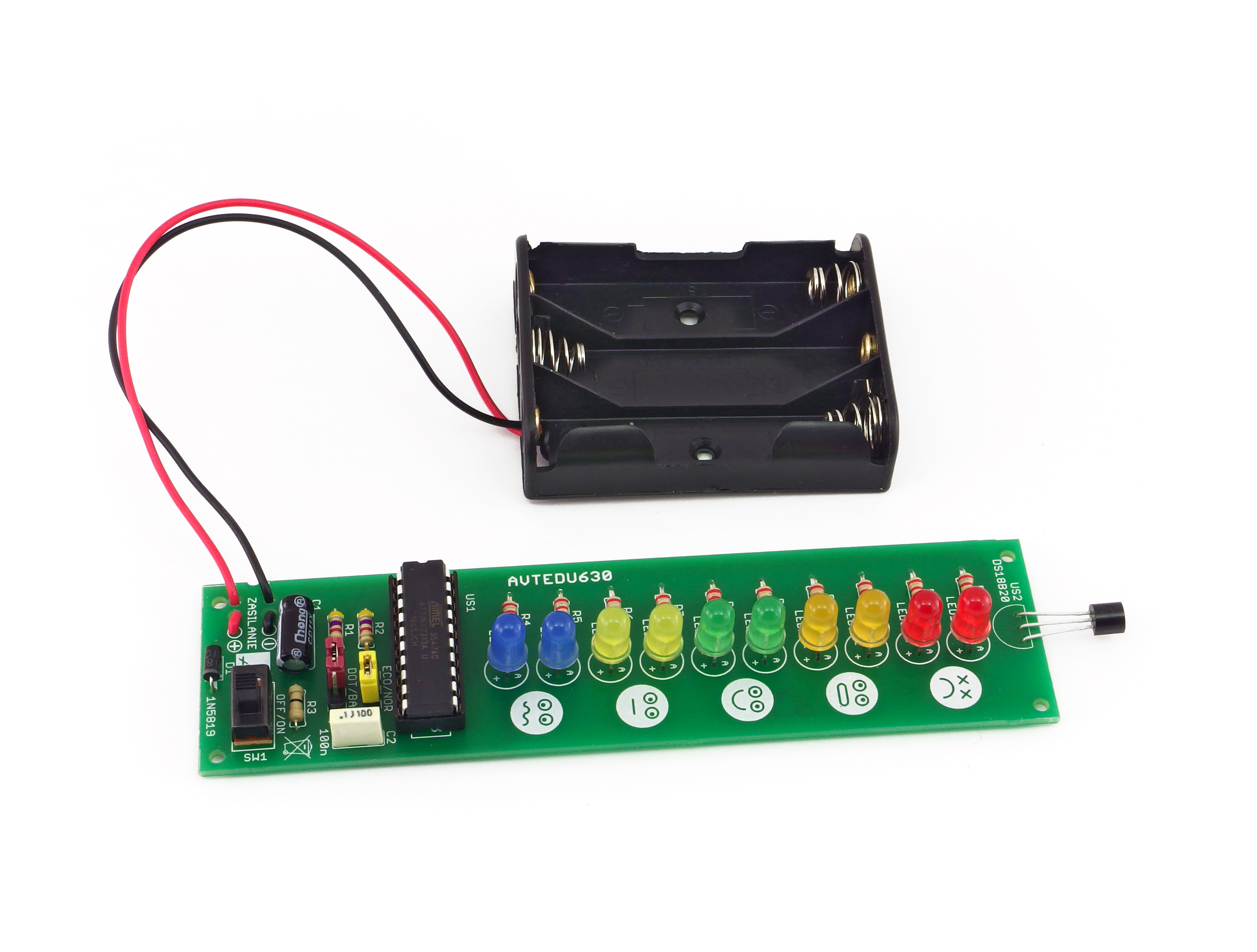
Thermometer module that indicates measured
temperature with a bar of colored LED diodes and
emoticons. The measurement range is 16°C-29°C.
ZOOM
https://bit.ly/3kf7A6S
PDF
DOWNLOAD
ThermoEmotic
Educational Soldering Kit
5 903890 000318
AVT EDU630
1

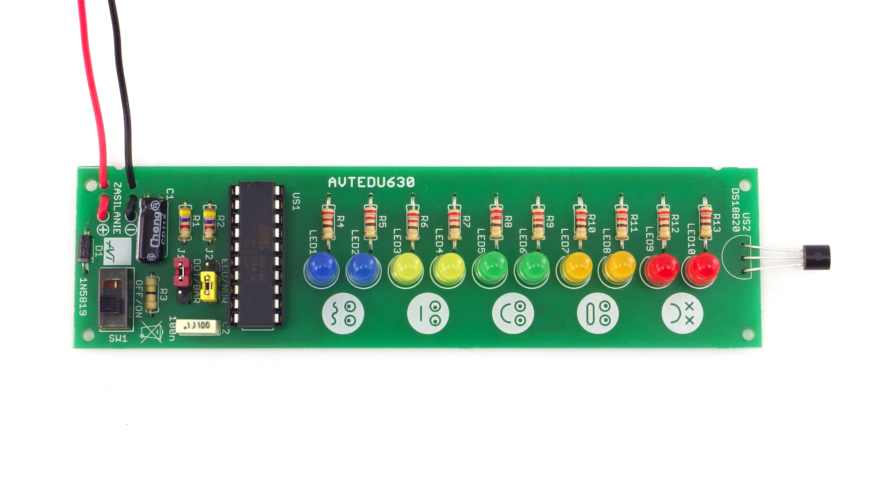
Figure 2. Position of the elements on the circuit board
Photo 1. View of the assembled circuit board (Click to view) ZOOM
Suggested order of assembly:
LED7, LED8:..........5mm orange LED diode !
J1, J2: .....................goldpin 1×3 + JUMPER
LED9, LED10:........5mm redLED diode !
⊝
battery connector: red-positive Ĺ, black-negative
SW1: ......................switch
R3: ...........................resistor 0Ω (black)
R4-R13:..................resistor 220Ω (red-red-brown-gold)
C2:...........................capacitor 100nF (can be marked as 104)
US1: ........................integrated circuit ATTINY2313 + IC socket !
US2: ........................integrated circuit DS18B20 !
D1:...........................1N5819 diode !
LED1, LED2:..........5mm blue LED diode !
LED3, LED4:..........5mm yellow LED diode !
LED5, LED6:..........5mm green LED diode !
C1:...........................capacitor 100µF ! (mounted on its side)
R1, R2:....................resistor 4,7kΩ (yellow-violet-red-gold)
Begin by soldering the elements onto the circuit board in order from smallest
to largest. When assembling the elements marked with “!” pay attention to
their polarity and placing of the notch.
You may find the frames with symbols of these elements on the circuit board, as well
as photos of the assembled kit helpful.
!
US2
C1 LED1-LED10
A
C
straight
side
A
K
D1 US1
1
continuous LED light
diodes pulsing
single diode light
sweeping the LED “line” -
down when temperature drops -
up when temperature rises
J1
J2
DOT
ECO
BAR
NOR
marker
marker
marker
straight
side
long
lead
2

ZOOM
ZOOM
Assembly instructions
1
1
2
2
3
3
4
4
of the element near the soldering field
Too much tin solder can result in forming a ball
instead of a cone or joining of two adjacent
soldering points.
seconds.
The whole process should take approx. 2-3
Inadequate temperature, amount of tin solder or
impurities can lead to so called “cold solder
joints, i.e. solder and the flux can’t moisten the
two surfaces and the resulting solder point is
fragile and in time will oxidize, break, and stop
working.
The cleanness of the soldered surfaces, right
amount of flux in the solder, adequately high
temperature (320-360°C), and sufficient amount of
solder are necessary to complete a correct
bonding.
Touch the tip of the soldering iron to the end
Next, apply tin solder
After the cone forms, remove tin solder first,
and then the soldering iron
3

Educational Electronics Kits are intended for educational and demonstration purposes only. They are not intended for use in
commercial applications. If they are used in such applications the purchaser assumes all responsibility for ensuring compliance
with all local laws. In addition, they cannot be used as a part of life support systems, or systems that for use as or as a part of life
support systems, or systems that might create a hazardous situation of any kind.
!
Thank you for purchasing AVT product. Please take your time to read carefully the important information below concering use of this
product.
• Never exceed the limits or ratings listed in the 'Specifications' section at the this user guide.
Failures in modern electronic component are very rare as 95% of non-working kits are due to poor soldering or components placed in
the wrong location or orientation so please check your work carefully.
• The product itself and all parts thereof (including packing material) are not suitable toys for childern! (choking hazard, risk of electric
shock, ...)
• If the kit is used to switch currents greater than 24V it is necessary to have the installation and performed by a trained professional
authorized for such work. The kit may only be used in such application if it was installed in a safe to touch enclosure.
• Battery or wall-adaptor are safe devices. They do not require special attention unless main voltage is connected to an output e.g. a
relay.
• If the kit is used in schools or educational facilities or similar institutions the operation must be supervised by trained and authorized
staff.
Notes
AVT SPV reserves the right to make changes without prior notice.
Assembly and connection of the device not in accordance with the instructions, unauthorized modification of components and any structural modifications may cause damage to the device and
endanger the person using it. In this case, the manufacturer and its authorized representatives shall not be liable for any damages arising directly or indirectly from the use or malfunction of the
product.
This symbol means do not dispose of your
product with your other household waste.
Instead, you should protect human health
and the environment by handing over your
waste equipment to a designated collection
point for the recycling of waste electrical
and electronic equipment.
Leszczynowa 11 Street,
03-197 Warsaw, Poland
http://avtkits.com/
AVT SPV Sp. z o.o.
4
/

