Page is loading ...

Thermo Fireman
DIY Soldering Educational Kit
ZOOM
AVT EDU649
1
• two flashing LEDs (red and blue)
As well as allowing you to develop your soldering
skills, our thermal alarm will make sure that you know
when, the temperature exceeds an acceptable, preset
value. When it is too high, i.e., rises above a preset
threshold, the device will start making a loud noise
and the red and blue LEDs will start flashing.
• operating range: approx. -30°C...+150°C
• integrated buzzer
• supply voltage: 9 VDC [6F22] - batteries not included
• board size: 77×63 mm
Specifications
Everyone likes to feel pleasant warmth, but it is
relative. Not everyone is able to say it's too hot - let
alone do something about it.
LM358
1k 10k
10k
3
2
1
IC1A
8
4
-
+
PIEZO
R1 PR1
R2
ON/OFF
LED1 LED2
Figure 1. Schematic diagram
kits
PDF
DOWNLOAD

2
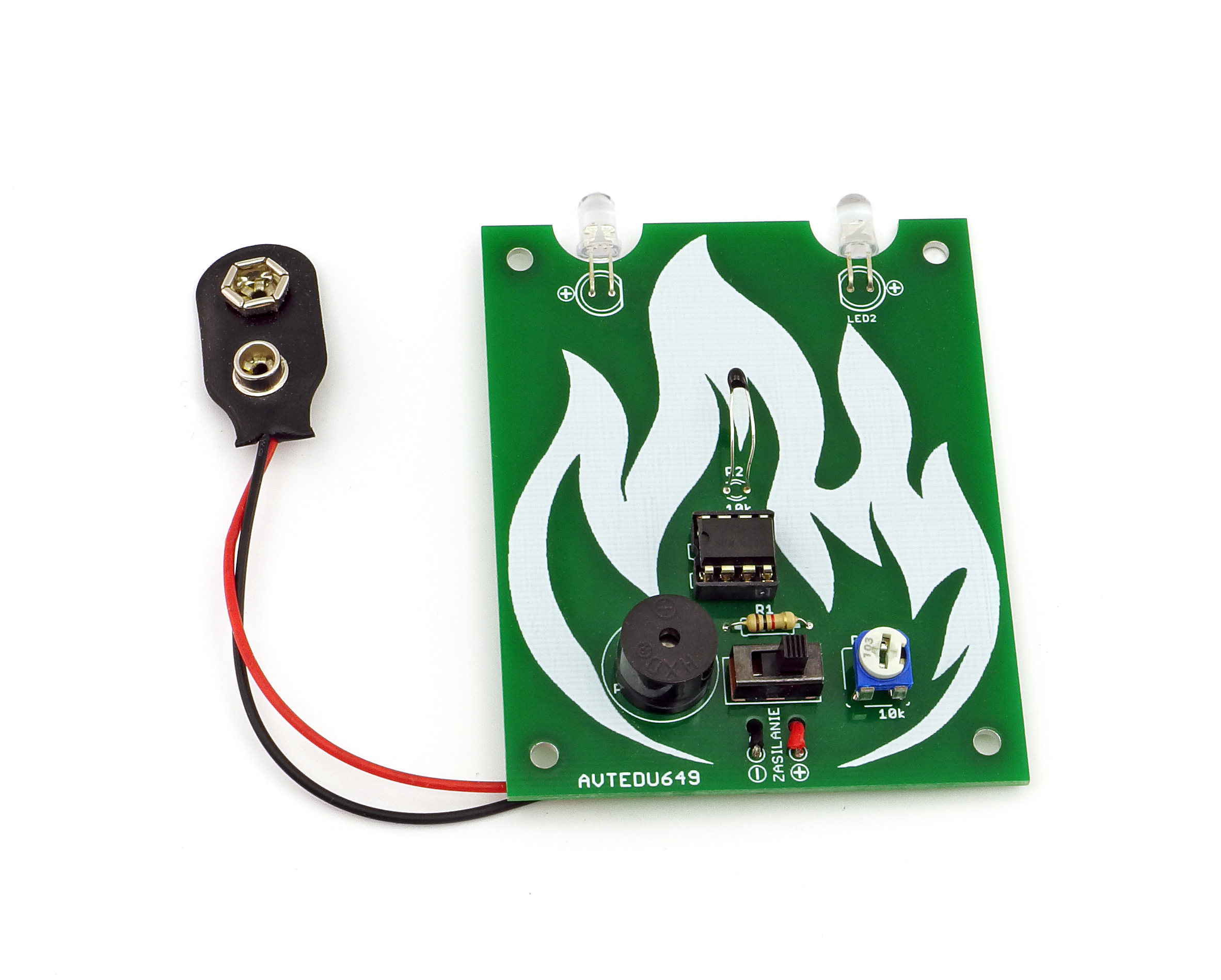
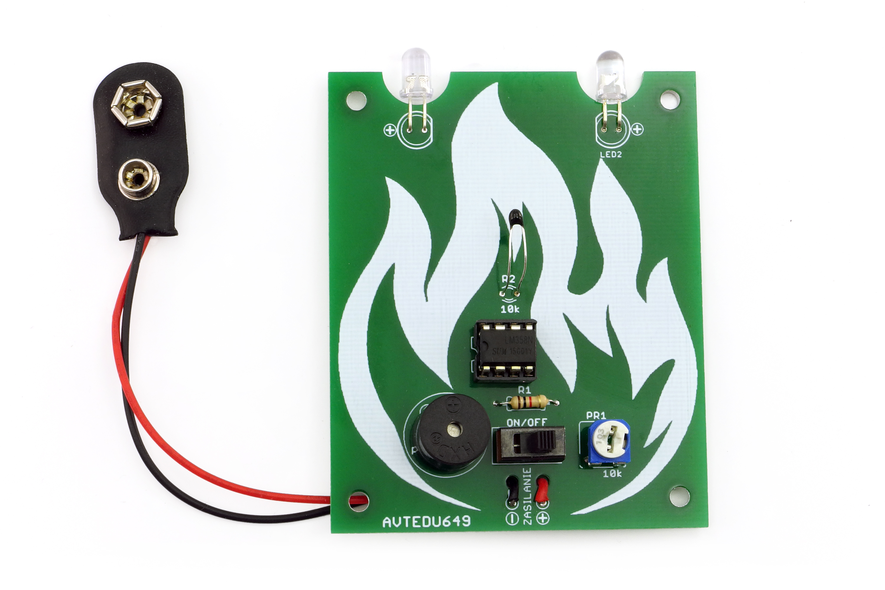
Figure 2. Arrangement of components on the PCB
Figure 2 shows the arrangement of the components
on the PCB. Solder the components sequentially onto
the board, starting with the smallest ones. The R2
thermistor must be soldered above the board, while
the LEDs must be soldered by profiling their leads as
shown in Figure 3. Once the circuit has been
mounted, check it carefully for correct installation.
Check that the components have not been soldered
in the wrong direction or in the wrong places and that
no soldering points have been short-circuited during
soldering.
Heat sensitivity of the screamer can be adjusted with
the PR1 potentiometer.
Mounting and start-up
Recommended mounting order:Recommended mounting order:Recommended mounting order:
IC1: .....................................LM358 + base !
R2:.......................................10 kΩ thermistor (sensor mounted above the board)
⊝
battery connector red Ĺ, black
LED1, LED2: .....................5 mm LEDs !
PR1: ...................................mounting potentiometer 10 kΩ
R1:.......................................1 kΩ (brown-black-red-gold)
ON/OFF: ...........................switch
PIEZO:................................piezo sounder !
Start mounting by soldering
components on the board,
in the order of their size, from
smallest to largest . When
mounting components marked
with an exclamation mark, pay
attention to their polarity.
To access high-resolution
images, download the PDF.
!
1
IC1
Marker
Marker
LED1
LED2
C
Trim
A
Components received in the kit, may differ in appearance from those
shown in the photograph. Despite this, they have the same parameters,
and their appearance will not affect their operation in the circuit.
!
ZOOM
MINMINMIN MAXMAXMAX
PDF
DOWNLOAD

3
Fig. 3 Mounting of the LED thermistor
PCB
PCB
R2- thermistor (temperature sensor)
5mm
LED1, LED2
ZOOM
Mounting instructions
1
1
2
2
3
3
4
4
the correct amount of binder.
Once the cone has formed, remove the 'tin’
joined, the presence of flux in the binder, a
soldering field
Then apply the "tin"/spoil
and then the soldering iron
solder are the cleanliness of the surfaces to be
sufficiently high temperature (320-360°C) and
leg/end of the component just outside the
The prerequisites for the formation of a correct
Too low a temperature or amount of binder, as
well as impurities, can lead to "cold solders", i.e.
the binder and the flux contained in it do not wet
the surfaces to be joined and an impermanent
solder is formed, which will oxidise over time, a
break will occur and the device will cease to
function
The entire process should take 2-3 seconds
Use the tip of a hot soldering iron to touch the Too much binder will cause a bead to form or two
adjacent solder points to join.
AVT SPV reserves the right to make changes without prior notice.Installation and connection of the appliance not in accordance with the instructions, unauthorised modification of
components and any structural alterations may cause damage to the appliance and endanger persons using it. In such a case, the manufacturer and its authorised representatives shall
not be liable for any damage arising directly or indirectly from the use or malfunction of the product.
The self-assembly kits are intended for educational and demonstration purposes only. They are not intended for use in commercial applications. If they are used in such applications, the
purchaser assumes all responsibility for ensuring compliance with all regulations
This symbol means do not dispose of your
product with your other household waste.
Instead, you should protect human health
and the environment by handing over your
waste equipment to a designated collection
point for the recycling of waste electrical
and electronic equipment.
Leszczynowa 11 Street,
03-197 Warsaw, Poland
https://sklep.avt.pl/
AVT SPV Sp. z o.o.
kits

Notes
4
/


