Page is loading ...

1
• signal-to-noise ratio: > 78 dB
• two-channel stereo system
Despite the explosive growth of digital audio
technology, "black" vinyl records remain an enduring
favorite among fans. To listen to them, you need a
turntable with an MM cartridge (with a moving
magnet) equipped with an amplifier with RIAA
characteristics.
• input voltage: (maximum) 55 mV
• gain: k = 38 dB (f = 1 kHz)
• non-linear distortion: < 0,08% (across the band)
• power supply: 12 V DC
• board dimensions: 41 × 53 mm
Characteristics
Recommendations: kit recommended for all music
fans using an analog turntable as a signal source.
The kit uses a good-quality dual operational amplifier
of the TDA2320A type. The features of this circuit
include a low-noise input stage that introduces
minimal linear and nonlinear distortion, full frequency
compensation (optimized for audio applications),
nearly 100 dB of channel separation, and high open-
loop gain. Due to the relatively low value of the SR
parameter (the rate of rise of the output voltage), the
circuit is designed for operation with signals with
small amplitudes. RC elements in the negative
feedback loop (the same for both channels) cause the
amplifier's frequency response to be established in
accordance with the RIAA standard.
Circuit description
ASSEMBLY DIFFICULTY
Gramophone preamplifier
with RIAA characteristics
Ku
(dB)
10 20 30 50 100 200 500 1k 2k 5k 10k 15k 20k f(Hz)
Figure 1. Characterization waveform Ku = f(f).
20
15
10
5
0
-5
-10
-15
-20
AVT 1023
PDF
DOWNLOAD

The assembly should be carried out in accordance with
standard considerations. In case of problems with circuit
excitation or "collecting" interference from the
environment (e.g., mains hum), the device should be
enclosed in a shielding box or the circuit board be
encased with appropriately cut pieces of sheet metal.
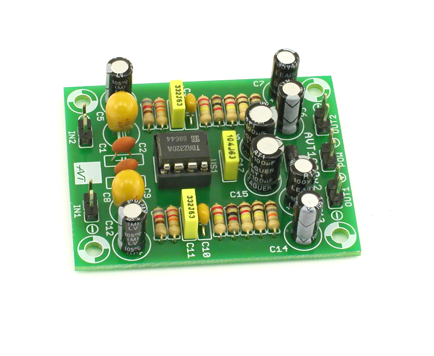
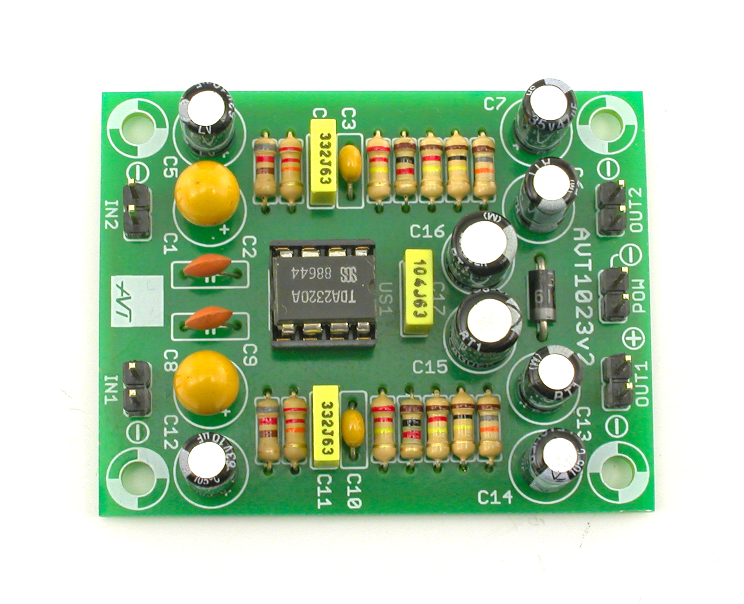
The layout of the components is shown in Fig. 2. The
supply voltage should be well filtered and stabilized.
The input and output wires should be shielded,
paying attention to the very accurate addition of the
shield to the circuit ground.
Assembly and start-up
Fig. 3. Example of connection
2
Fig. 1 Schematic diagram Fig. 2 Assembly diagram
IN1
OUT1
OUT2
IN2
+
-
D1
1N5819
ZOOM

List of elements
C1
C8
C5
C6
C7
C12
C13
C14
C15
C16
A
C
D1
1
US1
Resistors:
R1, R8:.................1 kΩ (brown-black-red-gold)
R2, R9: ................220 kΩ (red-red-yellow-gold)
R5, R12: ..............18 kΩ (brown-gray-orange-gold)
R3, R10: ..............22 kΩ (red-red-orange-gold)
Capacitors:
R7, R14: ..............120 kΩ (brown-red-yellow-gold)
R6, R13: ..............100 kΩ (brown-black-yellow-gold)
R4, R11: ..............820 Ω (gray-red-brown-gold)
C2, C9: ................82 pF (may be labeled 82)
C3, C10: ..............15 nF (may be labeled 153)
D1:........................1N5819 or similar !
C15, C16:............100 µF !
C7, C14: ..............47 µF !
OUT1, OUT2:.....goldpin 1×2 pins
C6, C13: ..............1 µF !
C1, C8:.................4,7 µF ! (may be labeled 475)
C17: .....................100 nF (may be labeled 104)
US1: .....................TDA2320A !
Other:
C4, C11: .............3,3 nF (may be labeled 332)
Semiconductors:
POW: ...................goldpin 1×2 pins
IN1, IN2: .............goldpin 1×2 pins
C5, C12: ..............10 µF !
3
To access high-resolution images as links, download the PDF. Download PDF.
The assembly should be started with soldering the components onto the board in order of size,
from smallest to the largest. When installing components marked with an exclamation mark, pay
attention to their polarity. You may find it helpful to have a wireframe with drawings of the leads and
symbols of these components on the board printed and photographs of the assembled set.
!
3
long
lead
marker
marker
marker
PDF
DOWNLOAD
AVT SPV reserves the right to make changes without prior notice. Assembly and connection of the device not in accordance with the indications within the instructions, arbitrary change of
components and any structural modifications may cause damage to the device and expose users to harm. In such a case, the manufacturer and its authorized representatives shall not be
liable for any damages arising directly or indirectly from the use or malfunction of the product.
DIY kits are intended for educational and demonstration purposes only. They are not intended for use in commercial applications. If they are used in such applications, the buyer assumes
all responsibility for ensuring compliance with all regulations.
Leszczynowa 11 Street,
03-197 Warsaw, Poland
AVT SPV Sp. z o.o. This symbol means do not dispose of your
product with your other household waste.
Instead, you should protect human health
and the environment by handing over your
waste equipment to a designated collection
point for the recycling of waste electrical
and electronic equipment.

Notes
4
/