AVT 3122 User manual

Type
User manual

AVT 3122 is a thermometer with LED display capable of measuring temperatures between -55 and 125 degrees Celsius. It features a waterproof sensor based on DS18B20, automatic sensor type detection, and a 4-digit LED display with a resolution of 0.1 degrees Celsius. The measurement result is updated every 2 seconds and the device can be powered by a DC power supply unit with a load current of 0.2A or more. It's easy to assemble and operate, making it suitable for various applications where temperature monitoring is required.

AVT 3122 is a thermometer with LED display capable of measuring temperatures between -55 and 125 degrees Celsius. It features a waterproof sensor based on DS18B20, automatic sensor type detection, and a 4-digit LED display with a resolution of 0.1 degrees Celsius. The measurement result is updated every 2 seconds and the device can be powered by a DC power supply unit with a load current of 0.2A or more. It's easy to assemble and operate, making it suitable for various applications where temperature monitoring is required.

1
Thermometer with LED display
• waterproof sensor based on DS18B20
• temperature range -55…+125°C
• power supply 7…15V DC/0.3A
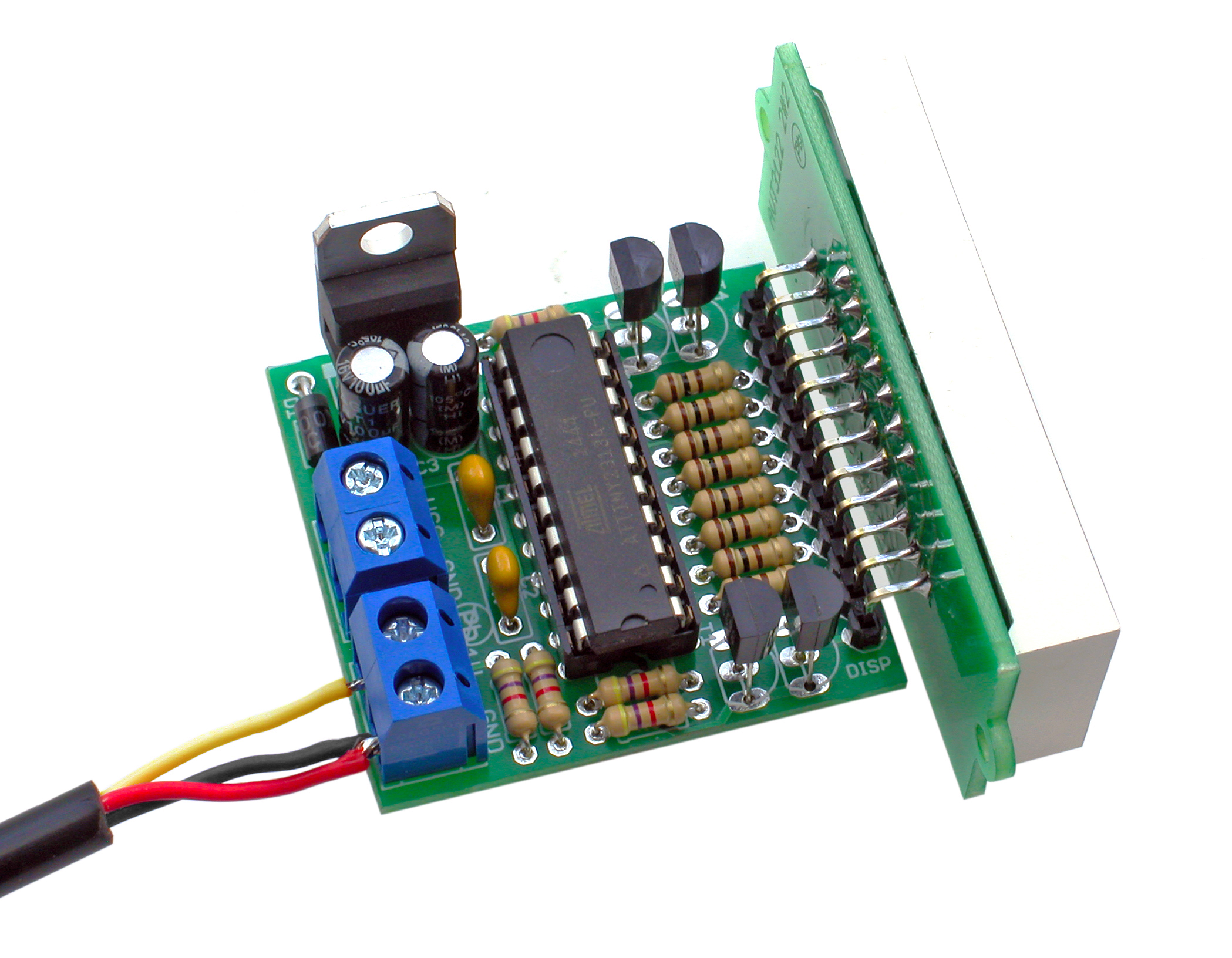
The thermometer measures the temperature
between -55°C and +125°C. It was built
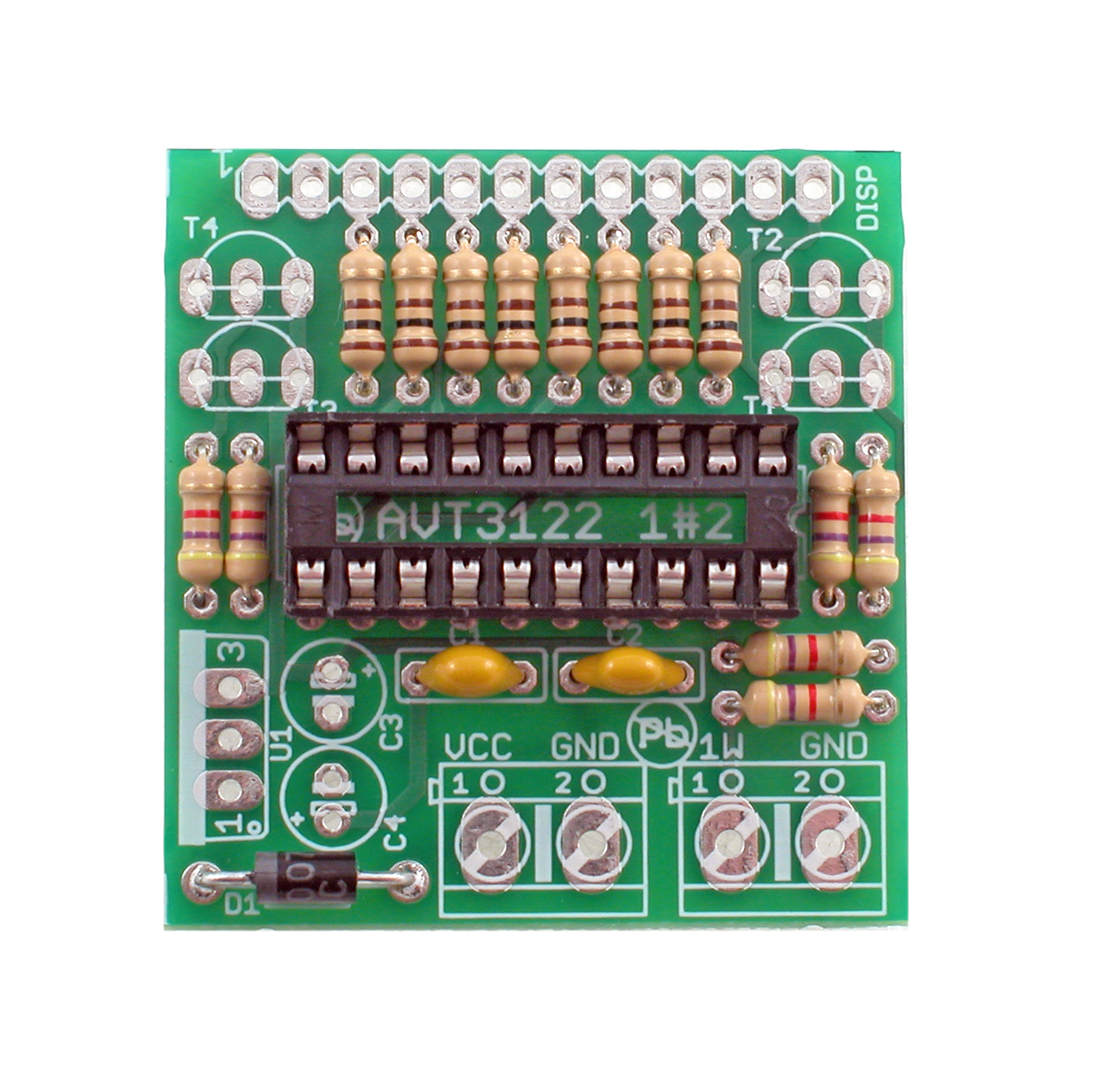
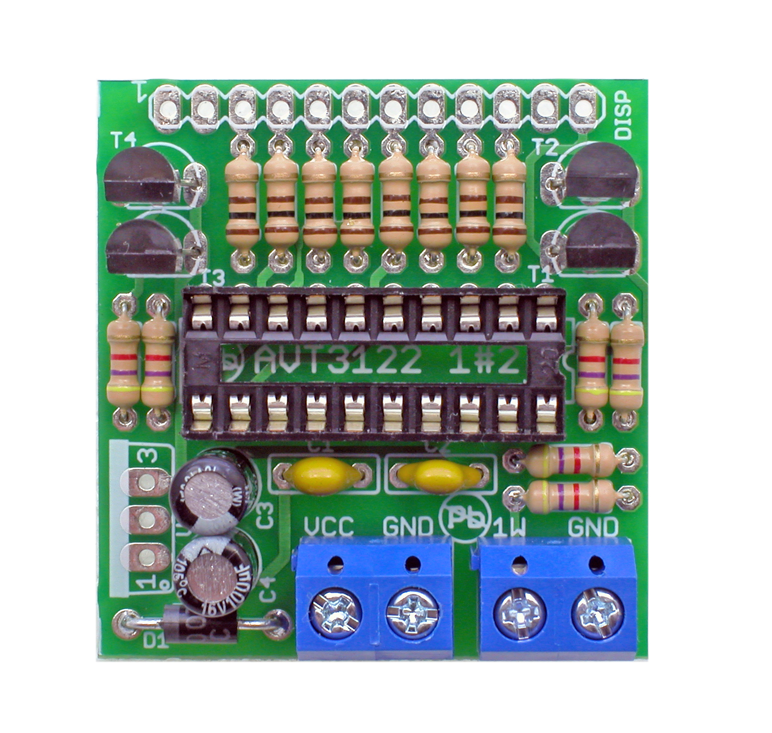
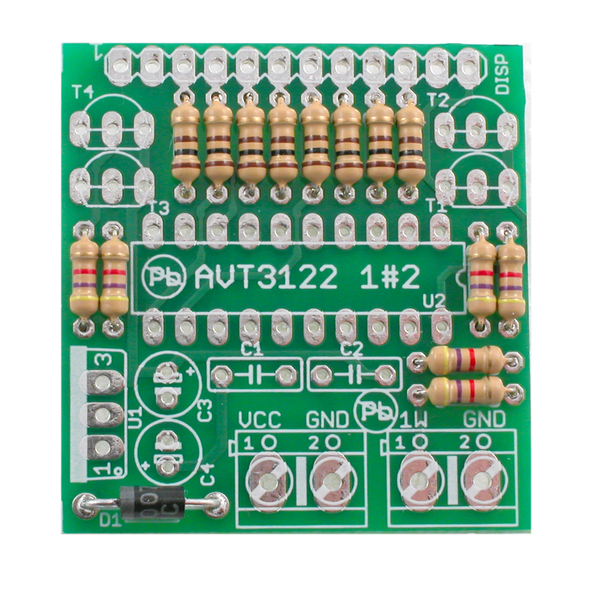
exclusively with THT components and a ready-
made waterproof temperature sensor.
Specifications
• LED display update every 2 seconds
• does not require adjustment or calibration
DS1820, DS18B20 or DS18S20 is used as
temperature sensor. Individual sensors differ in
their resolution and software driver.
The microcontroller software automatically
detects the type of connected sensor after
switching power on. The result of temperature
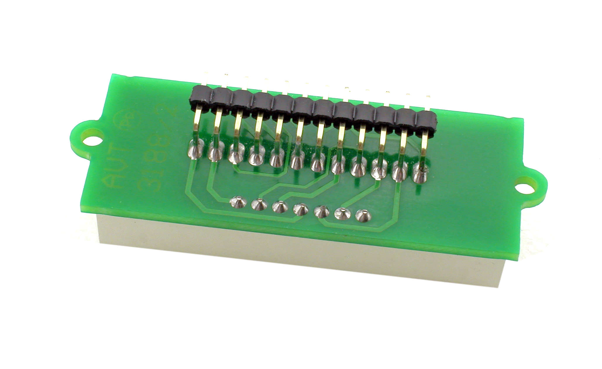
measurement is displayed on the 4 digit LED
display. Bipolar transistors T1…T4 are supplying
anodes of the LED digits while cathodes are
directly driven from microcontrollers outputs
via limit resistors R6…R13. The first position of
the LED display shows a minus sign, if the
measured temperature is less than 0. The
maximum resolution of the temperature
measurement is 0.1°C. The measurement result
is updated every 2 seconds.
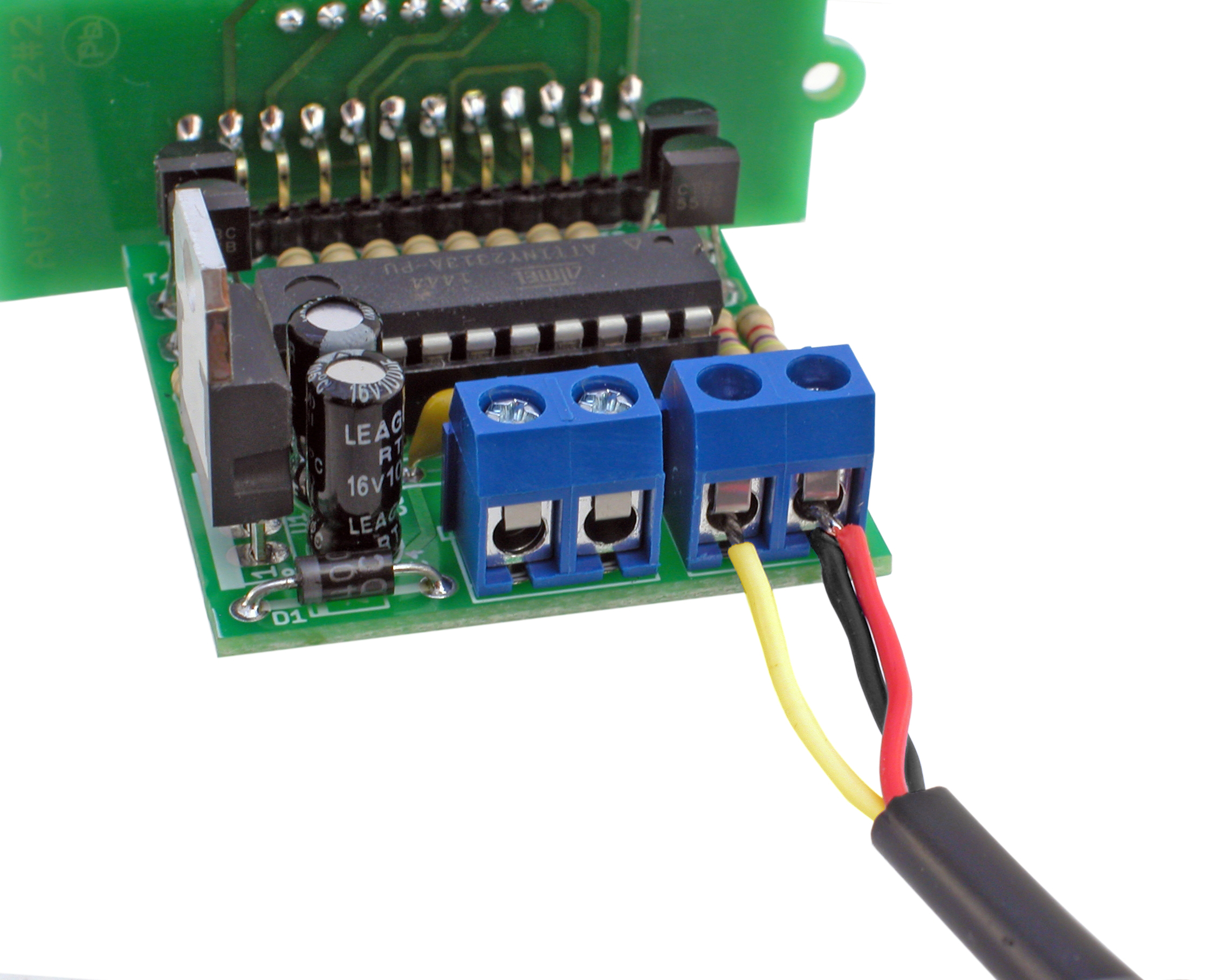
Schematic of the thermometer with LED display
is shown in Figure 1. The device should be
supplied with DC voltage within range from 7 to
15V connected to the POWER connector. It can
be any DC power supply unit with 0.2A load
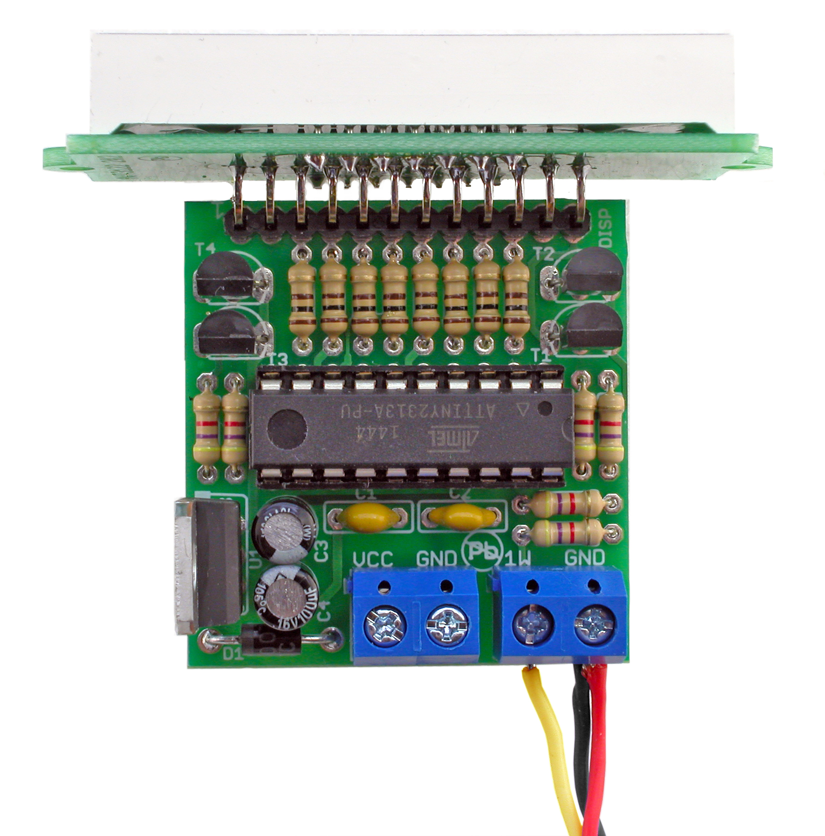
current or more. Diode D1 protects device from
faulty input polarity. Input voltage is applied to
voltage stabilizer U1. Microcontroller U2
(ATtiny2313) is responsible for all functionality
of the thermometer.
DIFFICULTY
LEVEL
http://bit.ly/2yT2Pxo
PDF
DOWNLOAD
Functional description
Thermometer with LED display
AVT 3122
5 9 0 3 8 9 0 0 0 0 2 2 6
The assembly is typical and should not cause
the problems. It runs in standard way starting
from the smallest components and ending with
the largest ones. After assembling both PCBs
should be connected together with the angled
goldpins.
The next step is to attach the temperature
sensor. For this purpose use a screw connector
mounted on the PCB: the yellow sensor cable
is connected to the 1W pin the black and red
cables are shorted and connected to the pin
marked GND. The way of attaching a
temperature sensor is shown in Figure 2.
Figure 1. Schematic diagram
AVT 3122
2
Thermometer with LED display
DIFFICULTY
LEVEL
Figure 2. How to connect the sensor
1
2
3
4
5
6
7
8
9
10
11
12
CON1 A
13
B
9
C
4
D
2
E
1
F
12
G
5
DP
3
AD1
14
AD2
11
AD3
10
AD4
6
UC
7
L C
8
DISP1
G
G
F
F
A
A
B
B
E
E
D
D
DP DP
V A 2
V A 2
V A 1
V A 1
C
C
V A 3
V A 3
V A 4
V A 4
T1...T4 BC557
R6...R13 100R
GND
1N4007
100n 100n 100u
4,7k
4,7k
4,7k
4,7k
4,7k
ATTINY2313
4,7k
GND
7805
100u
VCC
GND
GND
1W
POWER
D1
C1 C2 C3
R1
T4
T3
T2
T1
R5
R4
R3
R2
R6
R7
R8
R9
R10
R11
R12
R13
1
2
3
4
5
6
7
8
9
10
11
12
DISP
U2
(SCK)PB7 19
(MISO)PB6 18
(MOSI)PB5 17
PB4 16
(OCI)PB3 15
PB2 14
(AIN1)PB1 13
(AIN0)PB0 12
(ICP)PD6 11
(T1)PD5 9
(T0)PD4 8
(INT1)PD3 7
(INT0)PD2 6
(TXD)PD1 3
(RXD)PD0 2
GND
10 VCC
20
XTAL1
5
XTAL2
4
RESET
1
R14
U1
GND
VI
1
2
VO 3
C4
VCC
VCC
VCC
VCC
VCC
GND
A1
A1
A2
A2
A3
A3
A4A4
OA4
OA4
OA3
OA3
OA2
OA2
OA1
OA1
A
A
B
B
C
C
D
D
E
E
F
F
G
G
DP
DP
1WIRE
1WIRE
+
+
Assembly and test
Start off by soldering the printed circuit elements in order from smallest to largest. The unit assembled
flawlessly, using the supplied components will operate immediately after switching on the power supply.
ZOOM
Component list
Others:
DISP:....................LED-AF5643
C3, C4: ................100µF !
U1:........................7805 !
Resistors:
R6–R13: ..............100Ω (brown-black-brown-gold)
Capacitors:
Semiconductors:
T1-T4:..................BC557 (BC558) !
U2:........................ATtiny2313A with 20-pin IC socket
U3:........................DS18B20
1W: ......................2-pin terminal block connector
R1–R5, R14:.......4,7kΩ (yellow-violet-red-gold)
goldpin connector 14pin
VCC:.....................2-pin terminal block connector
C1, C2: ................100nF (also marked as 104)
D1: .......................1N4007 or similar !
3
DIFFICULTY
LEVEL
AVT 3122 Thermometer with LED display
C3
C4
U1 U2
A
C
D1
1
T1
T2
T3
T4
While assembling the components marked
with an exclamation mark attention should
be paid to their polarity. Symbols of the
components on the PCB as well as photos of
assembled sets may come in useful. To access high-
resolution images, download the PDF file.
!
PDF DOWNLOAD
Assembly in 4 steps
1
4
2
3
Solder resistors R1-R16 and diode D1
Solder capacitors C3, C4, U1, and LED display
with PCB, insert chip into socket
Solder capacitors C1, C2 and IC socket
Solder transistors T1-T4, PIEZO and connectors.
Solder LED display and goldpin connector
ZOOM
ZOOM
ZOOM
ZOOM
ZOOM
http://bit.ly/2yT2Pxo
4
DIFFICULTY
LEVEL
AVT 3122
Thermometer with LED display
Notes
Educational Electronics Kits are intended for educational and demonstration purposes only. They are not intended
for use in commercial applications. If they are used in such applications the purchaser assumes all responsibility for
ensuring compliance with all local laws. In addition, they cannot be used as a part of life support systems, or systems
that for use as or as a part of life support systems, or systems that might create a hazardous situation of any kind.
!
Thank you for purchasing AVT product. Please take your time to read carefully the important information below
concering use of this product.
• If the kit is used in schools or educational facilities or similar institutions the operation must be supervised by
trained and authorized staff.
• Never exceed the limits or ratings listed in the 'Specifications' section at the this user guide.
• Battery or wall-adaptor are safe devices. They do not require special attention unless main voltage is connected to
an output e.g. a relay.
Failures in modern electronic component are very rare as 95% of non-working kits are due to poor soldering or
components placed in the wrong location or orientation so please check your work carefully.
• If the kit is used to switch currents greater than 24V it is necessary to have the installation and performed by a
trained professional authorized for such work. The kit may only be used in such application if it was installed in a safe
to touch enclosure.
• The product itself and all parts thereof (including packing material) are not suitable toys for childern! (choking
hazard, risk of electric shock, ...)
AVT SPV reserves the right to make changes without prior notice.
Assembly and connection of the device not in accordance with the instructions, unauthorized modification of components and any structural modifications may cause
damage to the device and endanger the person using it. In this case, the manufacturer and its authorized representatives shall not be liable for any damages arising directly
or indirectly from the use or malfunction of the product.
This symbol means do not dispose of your
product with your other household waste.
Instead, you should protect human health
and the environment by handing over your
waste equipment to a designated collection
point for the recycling of waste electrical
and electronic equipment.
Leszczynowa 11 Street,
03-197 Warsaw, Poland
http://avtkits.com/
AVT SPV Sp. z o.o.
  • Page 1 1
  • Page 2 2
  • Page 3 3
  • Page 4 4

AVT 3122 User manual

Type
User manual

AVT 3122 is a thermometer with LED display capable of measuring temperatures between -55 and 125 degrees Celsius. It features a waterproof sensor based on DS18B20, automatic sensor type detection, and a 4-digit LED display with a resolution of 0.1 degrees Celsius. The measurement result is updated every 2 seconds and the device can be powered by a DC power supply unit with a load current of 0.2A or more. It's easy to assemble and operate, making it suitable for various applications where temperature monitoring is required.

Ask a question and I''ll find the answer in the document

Finding information in a document is now easier with AI