KITS LED Fan Educational Soldering Kit Operating instructions

Category
Soldering irons
Type
Operating instructions

KITS LED Fan Educational Soldering Kit lets you build a personal electric fan with 19 LED diodes that rotates with two selectable speeds and directions. You can use the buttons to switch the LED diodes with a phasing-out effect, creating a unique lighting display. This DIY kit is perfect for learning about electronics and soldering, and the assembled fan can be used as a fun and educational decoration.

KITS LED Fan Educational Soldering Kit lets you build a personal electric fan with 19 LED diodes that rotates with two selectable speeds and directions. You can use the buttons to switch the LED diodes with a phasing-out effect, creating a unique lighting display. This DIY kit is perfect for learning about electronics and soldering, and the assembled fan can be used as a fun and educational decoration.

• switching LED diodes with the phasing out effect
The effect of this module is achieved through a
system of 19 LED diodes grouped into 3 blade arms
and perfectly imitating the movement of a real fan.
Two operating buttons control direction and speed of
the LED animation and allow for hours of play and
creative use of the personally assembled circuit.
Specifications
• 19 LED diodes
• 2 buttons for controlling speed and direction
• power supply: 9VDC (6F22 battery not included)
• LED animation imitating a rotating electric fan
LED fan
Educational Soldering Kit
Figure 1. Schematic diagram
ZOOM
330 330 330 330 330 330 680
ATTINY13
OFF/ON
BC548 BC548 BC548
GND GND GND GNDGND
78L05
100n 100n
+9V +9V+5V
+5V
4.7k
4.7k
GND
GND
+5V
+5V
GND
4.7k 4.7k 4.7k
LED1
LED2
LED3 LED4
LED5
LED6 LED7
LED8
LED9 LED10
LED11
LED12 LED13
LED14
LED15 LED16
LED17
LED18
LED19
R1 R2 R3 R4 R5 R6 R7
PB5/PCINT5/RESET/ADC0/DW 1
PB3/PCINT3/CLKI/ADC3 2
PB4/PCINT4/ADC2 3
PB0/PCINT0/AIN0/OC0A/MOSI 5
PB1/PCINT1/AIN1/OC0B/INT0/MISO 6
PB2/PCINT2/SCK/ADC1/T0 7
VCC 8
GND 4
US2
SW1
T1 T2 T3
GND
IN OUT
US1
C1 C2
31
2 4
S1
31
2 4
S2
R8
R9
R10 R11 R12
Z2
Z1 SW1
SW1
SW2
SW2
CH1
CH1
CH2
CH2
CH3
CH3
https://bit.ly/2JPVLb0
PDF
DOWNLOAD
AVT EDU626
1
Figure 2. Position of the elements on the printed circuit board
ZOOM
2
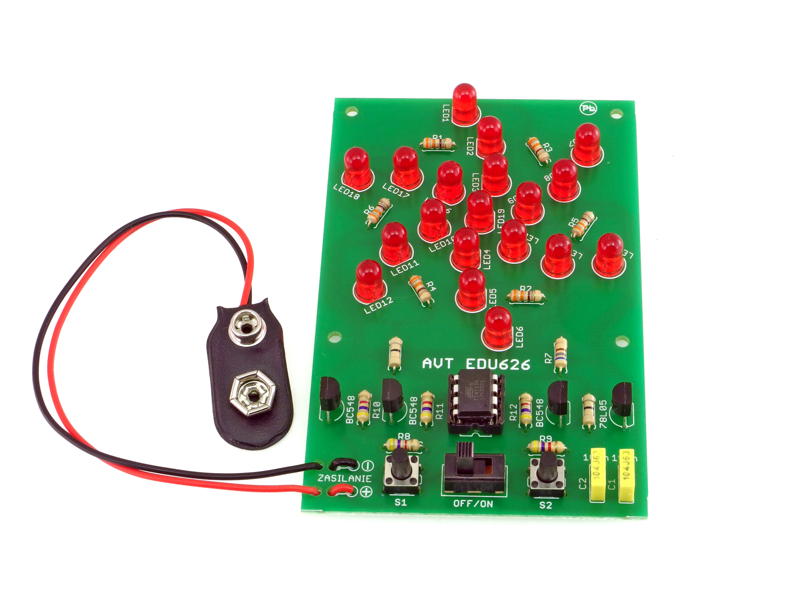
Suggested order of assembly:
Z1, Z2: ..............................resistor 0Ω (black)
R7: .....................................resistor 680Ω (blue-gray-brown-gold)
US1: ..................................78L05 !
SW1: .................................switch
T1-T3:...............................BC547 or BC548 !
battery connector:.......red-positive Ĺ, black-negative
S1, S2: ..............................microswitch
US2: ..................................integrated circuit ATTINY13A + IC socket !
R8-R12:............................resistor 4,7kΩ (yellow-violet-red-gold)
R1-R6: ..............................resistor 330Ω (orange-orange-brown-gold)
C1, C2:..............................capacitor 100nF (can be marked as 104)
LED1-LED19:..................5mm LED diode !
US1
T1
T2
T3
LED1-LED19
A
K
1
US2
Begin by soldering the elements onto the circuit board in order from smallest to largest.
When assembling the elements marked with “!” pay attention to their polarity and placing of the notch.
You may find the frames with symbols of these elements on the circuit board, as well as photos of the assembled kit helpful.
!
straight
side
straight
side
marker
marker
Assembly instructions
1
1
2
2
3
3
4
4
of the element near the soldering field
seconds.
Too much tin solder can result in forming a ball
instead of a cone or joining of two adjacent
soldering points.
The whole process should take approx. 2-3
Next, apply tin solder
After the cone forms, remove tin solder first,
and then the soldering iron
Inadequate temperature, amount of tin solder or
impurities can lead to so called “cold solder
joints, i.e. solder and the flux can’t moisten the
two surfaces and the resulting solder point is
fragile and in time will oxidize, break, and stop
working.
The cleanness of the soldered surfaces, right
amount of flux in the solder, adequately high
temperature (320-360°C), and sufficient amount of
solder are necessary to complete a correct
bonding.
Touch the tip of the soldering iron to the end
3
Educational Electronics Kits are intended for educational and demonstration purposes only. They are not intended for use in
commercial applications. If they are used in such applications the purchaser assumes all responsibility for ensuring compliance
with all local laws. In addition, they cannot be used as a part of life support systems, or systems that for use as or as a part of life
support systems, or systems that might create a hazardous situation of any kind.
!
Thank you for purchasing AVT product. Please take your time to read carefully the important information below concering use of this
product.
• The product itself and all parts thereof (including packing material) are not suitable toys for childern! (choking hazard, risk of electric
shock, ...)
Failures in modern electronic component are very rare as 95% of non-working kits are due to poor soldering or components placed in
the wrong location or orientation so please check your work carefully.
• If the kit is used to switch currents greater than 24V it is necessary to have the installation and performed by a trained professional
authorized for such work. The kit may only be used in such application if it was installed in a safe to touch enclosure.
• If the kit is used in schools or educational facilities or similar institutions the operation must be supervised by trained and authorized
staff.
• Never exceed the limits or ratings listed in the 'Specifications' section at the this user guide.
• Battery or wall-adaptor are safe devices. They do not require special attention unless main voltage is connected to an output e.g. a
relay.
Notes
Assembly and connection of the device not in accordance with the instructions, unauthorized modification of components and any structural modifications may cause damage to the device and
endanger the person using it. In this case, the manufacturer and its authorized representatives shall not be liable for any damages arising directly or indirectly from the use or malfunction of the
product.
AVT SPV reserves the right to make changes without prior notice.
This symbol means do not dispose of your
product with your other household waste.
Instead, you should protect human health
and the environment by handing over your
waste equipment to a designated collection
point for the recycling of waste electrical
and electronic equipment.
Leszczynowa 11 Street,
03-197 Warsaw, Poland
http://avtkits.com/
AVT SPV Sp. z o.o.
4
  • Page 1 1
  • Page 2 2
  • Page 3 3
  • Page 4 4

KITS LED Fan Educational Soldering Kit Operating instructions

Category
Soldering irons
Type
Operating instructions

KITS LED Fan Educational Soldering Kit lets you build a personal electric fan with 19 LED diodes that rotates with two selectable speeds and directions. You can use the buttons to switch the LED diodes with a phasing-out effect, creating a unique lighting display. This DIY kit is perfect for learning about electronics and soldering, and the assembled fan can be used as a fun and educational decoration.

Ask a question and I''ll find the answer in the document

Finding information in a document is now easier with AI