Page is loading ...

Invacare®UltraLowMaxxby
MotionConcepts
Supplementtopowerwheelchairusermanual
enModularPowerPositioningSystem
UserManual
ThismanualMUSTbegiventotheuseroftheproduct.
BEFOREusingthisproduct,readthismanualandsaveforfuturereference.

© 2018 Invacare Corporation
All rights reserved. Republication, duplication or modication i n w hole o r i n p art i s prohibited
without prior written permission from Invacare. Trademarks are identified by ™ and ®. All
trademarks are owned by or licensed to Invacare Corporation or its subsidiaries unless otherwise
noted.

Contents
1General.........................................5
1.1Introduction..................................5
1.2Symbolsinthismanual..........................5
1.3Warrantyinformation...........................5
2Safety..........................................7
2.1SafetyInformationonUsingtheSeatingSystem........7
3Components......................................9
3.1Powerpositioningfunctions.......................9
3.2SafetyLockoutandLimitSwitches..................10
4Setup...........................................13
4.1GeneralinformationonadjustingUltraLowMaxx......13
4.2Adjustmentpossibilityforremote..................13
4.2.1Adjustingtheheightoftheremote(onlyfor
swing–awayremotesupports)..................13
4.2.2AdjustingRemoteOffset......................14
4.3AdjustmentpossibilitiesforQuadLinkremote
support....................................14
4.3.1Adjustingremoteheight.......................14
4.3.2Adjustingremoteposition.....................14
4.3.3AdjustingLockTension........................15
4.3.4SwivellingRemotetoSide.....................15
4.4AdjustmentPossibilitiesforNucleusMidlineHolder.....16
4.4.1AdjustingDepthofMidlineHolder...............16
4.4.2AdjustingHeightofNucleusMidlineHolder........16
4.4.3AdjustingJoystick/DisplayPositiononNucleus
MidlineHolder.............................17
4.5AdjustingManualChinControl....................18
4.5.1AdjustingExtremityControlJoystick..............18
4.5.2AdjustingEggSwitch.........................19
4.6AdjustingHeadArray............................19
4.7AdjustingSipandPuffHeadArray..................20
4.8AdjustingSwing-AwayMechanism..................20
4.9AdjustingSwing-AwayDisplayHolder................21
4.10AdjustingSeatDepth...........................23
4.11AdjustingAngleofPresetBackrest.................23
4.12Adjustingcantileverip-uparmrest................23
4.13UltraRailMountedFlipBackCantileverMaxx
Armrest....................................25
4.14Adjustingtwopostreclinearmrest.................26
4.15AdjustarmpadwithMultiAxisUpperExtremity
Support(MACES).............................26
4.16AdjustingElbowBlock..........................27
4.17Hipsupportwithquickrelease...................28
4.18LateralTrunkSupportAdjustments.................31
4.19Adjustingtheheadrest.........................33
4.19.1InstallingheadrestadapterforEliteandHigh
Backs....................................34
4.19.2Auto–styleheadrestset-upandinstallation........34
4.19.3AdjustingElanheadresthardware...............35
4.19.4Adjustingmulti-axisheadresthardware...........36
4.20PivotPluslegrests.............................37
4.20.1SwingawayPivotPluslegrests.................37
4.20.2RemovingPivotPlusLegrests..................38
4.20.3AdjustingangleofPivotPluslegrests............39
4.20.4AdjustingWidth-andAngle-AdjustableFootplate....39
4.21Center-mountedlegrests—manuallyadjustable......40
4.21.1Removingthelegrest........................40
4.21.2Settingtheangleofthelegrest................41
4.21.3Settingthelengthofthelegrest...............41
4.21.4Settingtheangleofthefootplate...............42
4.21.5Settingtheangleandheightofthecalfpad.......42
4.22LNXlegrest..................................42
4.22.1Settingthelengthofthelegrest................42
4.22.2Settingtheangleofthefootplate...............43
4.22.3Adjustingfootplatewidthofcenter-mounted
legrest...................................43
4.22.4Settingtheangleofthefootplatform...........44
4.22.5SettingHeightandWidthofCalfPad............44

4.23Vari-Ffootrest................................45
4.23.1Swivellingthefootrest/legrestoutwardand/or
removing.................................45
4.23.2Settingtheangle...........................45
4.23.3Settingtheendstopofthefootrest............46
4.23.4Adjustingthelengthofthefootrest.............48
4.24Vari-Alegrests................................48
4.24.1Swivellingthefootrest/legrestoutwardand/or
removing.................................48
4.24.2Settingtheangle...........................48
4.24.3Settingtheendstopofthelegrest..............49
4.24.4Adjustingthelengthofthelegrest..............52
4.24.5Adjustingthedepthofthecalfpad.............52
4.24.6Adjustingtheheightofthecalfpad.............52
4.24.7Unlockingandswivellingthecalfpadbackward
whenalighting.............................53
4.24.8Adjustingtheangle–adjustablefootplate.........53
4.24.9Adjustingtheangle–anddepth–adjustablefoot
plate....................................54
4.25ADMlegrests................................54
4.25.1Swivellingthelegrestoutwardand/orremoving....54
4.25.2Settingtheangle...........................54
4.25.3Adjustingthelengthofthelegrest..............55
4.25.4Adjustingthedepthofthecalfpad.............56
4.25.5Adjustingtheheightofthecalfpad.............56
4.25.6Unlockingandswivellingthecalfpadbackward
whenalighting.............................57
4.25.7Adjustingtheangle–adjustablefootplate.........57
4.25.8Adjustingtheangle–anddepth–adjustablefoot
plate....................................58
4.26Poweredelevatinglegrests(ADElegrests)............58
4.26.1Swivellingthelegrestoutwardand/orremoving....58
4.26.2Settingtheangle...........................58
4.26.3Adjustingthelengthofthelegrest..............59
4.26.4Adjustingthedepthofthecalfpad.............59
4.26.5Adjustingtheheightofthecalfpad.............60
4.26.6Unlockingandswivellingthecalfpadbackward
whenalighting.............................60
4.26.7Adjustingtheangle–adjustablefootplate.........60
4.26.8Adjustingtheangle–anddepth–adjustablefoot
plate....................................61
4.27Imperialtometricconversionchart................61
5Usage..........................................63
5.1Rotating/RemovingReclineArmrest.................63
5.2RotatingCantileverArmrest.......................63
5.3Removing/insertinghipsupportwithquickrelease......65
5.4UsingLNXpoweredcenter-mountedlegrestwith
telescopingfootboard..........................65
5.5Swivellingtheremotetotheside..................66
5.6SwivellingNucleusMidlineHoldertoSide............66
5.7SwivellingSwing-AwayDisplayHoldertoSide..........66
6Maintenance.....................................67
6.1Maintenanceschedule...........................67
7Troubleshooting...................................68
7.1PerformanceTroubleshooting.....................68
8TechnicalData....................................71
8.1TechnicalSpecications..........................71

General
1General
1.1Introduction
Thisusermanualcontainsimportantinformationaboutthe
handlingoftheproduct.Toensuresafetywhenusingthe
product,readtheusermanualcarefullyandfollowthe
safetyinstructions.Alsocarefullyreadtheusermanualof
yourpowerwheelchair.
Notethattheremaybesectionsinthisdocument,whichare
notrelevanttoyourproduct,sincethisdocumentapplies
toallavailablemodels(onthedateofprinting).Ifnot
otherwisestated,eachsectioninthisdocumentreferstoall
modelsoftheproduct.
Themodelsandcongurationsavailableinyourcountrycan
befoundinthecountry-specicpricelists.
Invacarereservestherighttoalterproductspecications
withoutfurthernotice.
Beforereadingthisdocument,makesureyouhavethe
latestversion.YoundthelatestversionasaPDFonthe
Invacarewebsite.
Ifyoundthatthefontsizeintheprinteddocumentis
difculttoread,youcandownloadthePDFversionfromthe
website.ThePDFcanthenbescaledonscreentoafont
sizethatismorecomfortableforyou.
Formoreinformationabouttheproduct,forexample
productsafetynoticesandproductrecalls,contactyour
Invacarerepresentative.Seeaddressesattheendofthis
document.
1.2Symbolsinthismanual
Inthismanual,hazardstatementsareindicatedbysymbols.
Thesymbolsareaccompaniedbyasignalwordthatindicates
theseverityoftherisk.
WARNING
Indicatesahazardoussituationthatcouldresult
inseriousinjuryordeathifitisnotavoided.
CAUTION
Indicatesahazardoussituationthatcouldresult
inminororslightinjuryifitisnotavoided.
IMPORTANT
Indicatesahazardoussituationthatcouldresult
indamagetopropertyifitisnotavoided.
Givesusefultips,recommendationsand
informationforefcient,trouble-freeuse.
ThisproductcomplieswithDirective93/42/EEC
concerningmedicaldevices.Thelaunchdate
ofthisproductisstatedintheCEdeclaration
ofconformity.
Thissymbolidentiesalistofvarioustools,
componentsanditemswhichyouwillneedin
ordertocarryoutcertainwork.
1.3Warrantyinformation
Weprovideamanufacturer’swarrantyfortheproduct
inaccordancewithourGeneralTermsandConditionsof
Businessintherespectivecountries.
1585725-G5

Invacare®UltraLowMaxxbyMotionConcepts
Warrantyclaimscanonlybemadethroughtheprovider
fromwhomtheproductwasobtained.
61585725-G

Safety
2Safety
2.1SafetyInformationonUsingtheSeating
System
YourUltraLowMaxxseatingsystemhasbeenspecially
conguredandassembledtothewheelchairbasepriorto
delivery.Notethatthenalcongurationandpurchasing
decisionregardingthecompletewheelchairsystemis
theresponsibilityofthepowerwheelchairuser,whois
capableofmakingsuchadecision,andhis/herhealthcare
professional.Thecontentsofthismanualarebasedon
theexpectationthatamobilitydeviceexperthastted
thepowerwheelchairtotheuserandhasassistedthe
prescribinghealthcareprofessionalintheinstructionand
useofthisdevice.
Theusermanualofthepowerwheelchaircontainsall
relevantsafetyinformationabouttheuseofthepower
wheelchairincludingtheseatingsystem.Becertaintoread
andfollowthesesafetyinformation.
WARNING!
RiskofTipping
Thepowerwheelchairmaytipoverwhenyou
changeitsstabilitycharacteristicsbychanging
yourseatingposition.
–Determineandestablishyourpersonalsafety
limitsbypracticingbending,reachingand
transferringactivitiesinthepresenceof
aqualiedhealthcareprofessionalbefore
attemptingactiveuseofthewheelchair.
–YourUltraLowMaxxseatingsystemcanbe
mountedontothebaseinvariousforwardand
aftpositions.Makecertainthattheposition
selectedprovidesyouwithmaximumstability
overthefullrangeofseatingpositions.
–Considerallpersonalgearandaccessories
(backpacks,ventsystems,extrabatteries,
etc.)thatwillbecarriedonthewheelchair.
Forexample,aloadedbackpack,attached
tothebackoftheseatingsystem,can
signicantlyreducetherearwardstabilityof
yourwheelchair .
1585725-G
7

Invacare®UltraLowMaxxbyMotionConcepts
WARNING!
RiskofTipping(Continued)
–Considerthebackrestbeingused.Forexample,
arecessedbackcanshiftyourcenterofgravity
backwardandsignicantlyreducetherearward
stabilityofthewheelchair .Conversely,athick
backcushionwillshiftyouforwardandreduce
thewheelchairsforwardstability.
–Alwaysshiftyourweightinthedirectionyou
areturning.Shiftingweightintheopposite
directionoftheturnmaycompromisestability
ofthewheelchairbase,causingittotipover.
–Considertheseatcushionbeingused.Athick
seatcushionwillraiseyourcenterofgravity
andreducethewheelchairsstabilityinall
directions.
–AllUltraLowMaxxsystemsareequippedwith
drivelockouts.Makecertainthisissetsoas
nottocompromiseyourstabilitywhiledriving
(referto3.2SafetyLockoutandLimitSwitches,
page10).
–Thewheelchairhasaprogrammablecontroller
whichallowsadjustmentofthemaximum
accelerationanddecelerationofthewheelchair.
Makesurethatthesearesettoanappropriate
levelforthesystemandforyou,theuser .
WARNING!
RiskofTipping(Continued)
–Whenoperatinginreducedspeeddriveor
anti-tipperlockout,alwaystravelonasmooth
levelsurfacetoensurethewheelchair’sstability
isnotcompromised.
–Ensureallmedicalconditionsareconsidered
whensettingupyourwheelchair.Involuntary
musclemovementsuchasspasmsmayaffect
thestabilityofthewheelchair,especiallywhen
theseatingsystemisinatiltedorreclined
position.
–Whenasystemisfullytiltedorreclined,
thefrontwheelsofthewheelchairshould
nevercomeofftheground.Ifthisoccurs,
pleasecontactyourauthorizedInvacaredealer
immediatelytoresolvetheissue.
81585725-G

Components
3Components
3.1Powerpositioningfunctions
Theseatingsystemoffersthefollowingfunctions:
CG-TILT
TheCG(centerofgravity)tiltfunctioncompensatesfor
weightshiftbyslidingthepivotaxisandentireseatassembly
forwardastheseattiltsback.Typicaltiltrangeis0°-45°
(withlifter)or0°-50°(withoutlifter).
RECLINE
Thereclinefunctionenablesuserstoinnitelychangethe
seattobackangleoftheirsystemwithinasetrange.Typical
reclineanglerangeis90°-168°.
ESR
ESR(extendedshearreduction)issynchronizedwithrecline
toreducetheamountofshearbetweentheclientandthe
backrest.Thisisaccomplishedusingalinkagethatslidesthe
backrestonthebackpostsasthebackreclines.
PRECLINE
Availableasanoptionwithreclinesystems,preclineadjusts
thebackangleoftheseatingsystemintoaforwardposition,
closingtheseattobackangletolessthan90°.(Note:the
maximumreclineangleisdecreasedapproximatelybythe
numberofdegreesofprecline).
SCISSORLIFTER/LIFTERMODULE
Thescissorliftermoduleallowsuserstoraisetheirpower
positioningsystemupto300mmabovethelowest
seat-to-oorheightoftheirsystem.Thescissorlifteris
combinedwithatiltfunction.
LEGRESTS
Ourwiderangeofpowerandmanuallegrestsareavailable
inanarrayofsizesandstylesincludingindividuallegrests
andcenter-mountedfootplatformstohelpsecureand
positionclients’legs.Inaddition,weofferamultitudeof
legresthangerstoaccommodateyourlegrestchoice.Power
legrestsmaybeprogrammedtooperateinoneofthetwo
followingcongurations:
•Individual(legrestsoperateindependently),
•Combined(legrestsoperateinunison)
1585725-G9

Invacare®UltraLowMaxxbyMotionConcepts
3.2SafetyLockoutandLimitSwitches
DANGER!
RiskofSevereInjuryorDeath
Theangleatwhichthelimitswitches/lockouts
aresetiscriticaltothesafeoperationofthe
seatingsystem.
–Invacarewillnotbeliableforanyinjuriesor
damagesustainedwhenadjustmentsaremade
beyondthefactoryrecommendedsettings.
–Toensureproperset-up,adjustmentstosafety
lockoutsandlimitsshouldonlybeperformed
byaqualiedtechnician.
–Neverexceedthemaximumrecommended
limits.Safetylockoutsandlimitswitchesshould
besetuptobestmeettheneedsoftheuser
withoutcompromisingtheoverallstabilityof
thewheelchair.
–Followinganylimitorlockoutadjustments,
alwaystesttheseatingsystemoverthefull
rangeofmotion(i.e.tilt,recline,lifter)to
verifytherevisedset-upisfunctioningproperly
andensurethattherearenoresultingstability
orinterferenceissues.
Additionalsafetylimitsandlockoutswitchesmaybe
requiredformorecomplicated/specializedseating
systems.Forinformationonlimits/lockoutsthatare
notidentiedinthismanual,pleasecontactour
TechnicalServiceDepartmentforassistance.
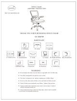
Tilt/ReclineDriveLockout(DLO)Limit
Alltiltandreclineseatingsystemsareequippedwitha
drivelockout(DLO)limittopreventthewheelchairfrom
beingdrivenwhentheseatingsystemistiltedorreclined
beyondapre-determinedsafetotalangle.Thetotalangle
canbeanycombinationofseatangle,backrestangleand/or
surfaceangle.Drivelockoutonlyrespondswhenyouadjust
anglesinstandstill.
TheDLOlimitissettoamaximumof60°(TDXSP2)/50°
(Storm
4
).OntheStorm
4
,anadditionalswitchactivatesthe
DLOifthetiltangleexceeds25°.
Fig.3-1
(Anglemeasuredfromvertical)
LifterReducedDriveSpeed(RDS)Limit
Seatingsystemsthatareconguredwithascissorlift
modulearecongured/programmedwithaReducedDrive
Speedlimit.Thelimitutilizesmicroswitchestotriggerthe
seatingsystemintoreducedspeeddriveassoonas:
•theseatingsystemisraisedtoapre-determinedheight
beyondthehome(fullyretracted)position,or
101585725-G

Components
•theseatingsystemistiltedoutsideofapre-determined
anglerange.
Tilt/Recline/Lifter
(T/R/L)systems:
RDSlimit=
•max.100mm(TDX
SP2)
•10mm(Storm
4
)
•130°–90°
Fig.3-2Homeposition(left),LifterRDSlimit(right)
Fig.3-3TiltRDSlimit
Max.BackAngleLimit
Themaximumtiltlimitestablishesthemaximumbackangle
fortheseatingsystemattilt/reclinecombined.Thefunction
ofthislimitistopreventthebackanglefromextending
beyondamaximumpre-setangle.UltraLowMaxxseating
systemsaretypicallypresetatthefactorytothemaximum
allowableangleanddonotrequireanyfurtheradjustment
unlessthemaximumangleneedstobedecreased(see
hazardstatementbelow).
Tilt/Recline:Max.Tilt/ReclineLimit=168°
RiskofDamagetoWheelchair
–Whenestablishingthemaximumbacklimit,
alwaysconsiderthesizeandlocationofany
personalgearthatmaybecarriedonthe
wheelchair,asitcouldcauseinterference
betweenthebackrestandthewheelchairbase
whenfullytilted/reclined,anddamagethe
actuatorand/orwheelchair .
Fig.3-4Max.Tilt/ReclineLimit(max.backangle)
LifterLockout
Liftersystemsareequippedwithalifterlockouttoprevent
thelifteractuatorfromraisingwhenthesystemistiltedor
reclinedmorethan60°(TDXSP2)/50°(Storm
4
combined
angle)/25°(Storm
4
tiltangle).
1585725-G
11

Invacare®UltraLowMaxxbyMotionConcepts
TDXSP2:
Max.60°>60°
Storm
4
combined
angle:
Max.50°>50°
Storm
4
tiltangle:
Max.25°>25°
12
1585725-G

Setup
4Setup
4.1GeneralinformationonadjustingUltraLow
Maxx
CAUTION!
Damagetomobilitydeviceandaccidenthazard
Itispossiblethatcollisionscanoccurbetween
mobilitydevicecomponentsduetovarious
combinationsofadjustmentoptionsandtheir
individualsettings
–Themobilitydeviceisttedwithanindividual,
multiplyadjustableseatingsystemincluding
adjustablelegrests,armrests,aheadrestor
otheroptions.Theseadjustmentoptionsare
describedinthefollowingchapters.They
areusedtoadapttheseattothephysical
requirementsandtheconditionoftheuser .
Whenadaptingtheseatingsystemandtheseat
functionstotheuser,ensurethatnomobility
devicecomponentscollide.
4.2Adjustmentpossibilityforremote
Thefollowinginformationisvalidforallseatingsystems.
CAUTION!
Riskoftheremotebeingpushedbackwards
duringanaccidentalcollisionwithanobstacle,
suchasadoorframeortable,andthejoystick
beingjammedagainstthearmpadiftheposition
oftheremoteisadjustedandallscrewsarenot
completelytightened
Thiswillcausethemobilitydevicetodrive
forwarduncontrollablyandpotentiallyinjurethe
mobilitydeviceuserandanypersonstandingin
theway.
–Whenadjustingthepositionoftheremote,
alwaysmakesuretotightenallscrewssecurely.
–Ifthisshouldaccidentallyhappen,immediately
switchthemobilitydeviceelectronicsOFFat
theremote.
CAUTION!
Riskofinjury
Whenleaningontheremote,forexample,when
transferringintooroutofthewheelchair,the
remoteholdermaybreakandtheusermayfall
outofthechair.
–Neverleanontheremoteasasupportfor,for
example,transfer .
4.2.1Adjustingtheheightoftheremote(onlyfor
swing–awayremotesupports)
•6mmAllenkey
1585725-G13

Invacare®UltraLowMaxxbyMotionConcepts
1.LoosenAllenscrewA.
2.Adjustremotetodesiredheight.
3.Re-tightenAllenscrew.
4.2.2AdjustingRemoteOffset
Theremotecanbeadjustedby20mm(0.8inch)sidewise.
•3mmAllenkey
Fig.4-1
1.LoosenAllenscrewsA.
2.Adjustremotetodesiredoffset.
3.Re-tightenAllenscrews.
4.3AdjustmentpossibilitiesforQuadLink
remotesupport
4.3.1Adjustingremoteheight
1.LoosenthetwosetscrewsAontheremotemount.
2.Pushorpulltheremotemountingtubeupordown
tothedesiredheight.
3.Tightenthetwosetscrewsontheremotemount.
4.3.2Adjustingremoteposition
Performthisproceduretoadjustthepositionoftheremote
ontheQuadLink.
14
1585725-G

Setup
1.LoosenscrewAsecuringadjustableremotetrayBto
QuadLink.
2.Rotateremotetodesiredposition.
3.TightenscrewtosecureadjustableremotetraytoQuad
Link.
4.3.3AdjustingLockTension
Bydefault,theQuadLinkisttedwithtwomagnetslocking
theQuadLinkinextendedposition.Removingamagnet
reducesthetensionandmakesiteasiertoreleasetheQuad
Link.
CAUTION!
RiskofInjuryorDamagetoWheelchair
RemovingbothmagnetsleavesQuadLinkwithout
lock.QuadLinkcouldretractunintentionally.
–Alwaysleaveatleastonemagnet.
•Smallpointedtoolsuchaspaperclip
1.SwivelQuadLinktosidetoaccessmagnets.
2.InserttoolinholeAandpushoutmagnetonother
side.
4.3.4SwivellingRemotetoSide
WARNING!
–Makesurengersarenotbetweenthelinkage
barswhenlockingtheQuadLinkretractable
remotemountintoposition.Pinchpointswill
occurbetweenthelinkagebarswhenlocking
theQuadLinkintoposition.
1585725-G15

Invacare®UltraLowMaxxbyMotionConcepts
SwivelRemotetoSide
1.
Toretractremotefromnormalextendedposition,push
outwardoninsidesurfaceofremoteuntilQuadLink
isfree.
TheQuadLinkworksthebestwhentheremote
ispushedoutwardontheinsidesurfaceofthe
remote,nearthearmrestpad.
2.PushremoteoutwardandrearwarduntilQuadLink
movesthroughitscompleterangeintoitsfullyretracted
position.
ReturnRemotetoExtendedPosition
1.
Toreturnremotetonormalextendedposition,push
outwardoninsidesurfaceofremote,thenforwardand
inwarduntilQuadLinkmovesthroughitscomplete
rangeandclicksintoitsfullyextendedposition.
4.4AdjustmentPossibilitiesforNucleusMidline
Holder
CAUTION!
RiskofInjuryandDamage
Remainingburrsandmissingendcapsafter
modicationsonrods,suchasshortenedrod,can
leadtoinjuryordamage.
–Deburrcutaftercuttingexcessivelength.
–Re-installendcapafterdeburring.
4.4.1AdjustingDepthofMidlineHolder
1.LoosenleverA.
2.Shiftmidlineholdertodesiredposition.
3.Tightenlever.
4.4.2AdjustingHeightofNucleusMidlineHolder
Youcanadjusttheheightofthenucleusmidlineholderin
twoways:
•Adjustittogetherwiththearmrestheight.Referto
correspondingarmrestchapters.
•Adjusttheheightofthenucleusmidlineholderonly.
Refertosectionbelow.
161585725-G

Setup
•3/16”Allenkey
1.LoosenscrewA.
2.Adjustnucleustodesiredheight.
3.Tightenscrew.
4.4.3AdjustingJoystick/DisplayPositiononNucleus
MidlineHolder
DLX-REM500
•3/16”Allenkey
1.LoosenscrewA.
2.Positiondisplayonnucleus.
3.Tightenscrew.
DLX-CR400andDLX-CR400LF
•5/32”Allenkey
1.LoosenscrewsA.
2.Positionjoystickonnucleus.
3.Tightenscrews.
•1/8“Allenkey
1.LoosenscrewA.
2.Openclampandpositionjoystickonnucleus.
3.Tightenscrew.
ASLComponentsonNucleusTray
•3/16”Allenkey
1585725-G
17

Invacare®UltraLowMaxxbyMotionConcepts
Thefollowinggraphicservesasanexample.
1.LoosenscrewA.
2.Positionjoystickonnucleus.
3.Tightenscrew.
ASLComponentsonNucleusOnly
•5/32”Allenkey
Thefollowinggraphicservesasanexample.
1.LoosenscrewA.
2.Positionjoystickonnucleus.
3.Tightenscrew.
4.5AdjustingManualChinControl
CAUTION!
RiskofInjuryandDamage
Remainingburrsandmissingendcapsafter
modicationsonrods,suchasshortenedrod,can
leadtoinjuryordamage.
–Deburrcutaftercuttingexcessivelength.
–Re-installendcapafterdeburring.
4.5.1AdjustingExtremityControlJoystick
AdjustingJoystickOrientation
Thejoystickcanbeturnedthrough360degrees.Asloton
thesideallowsyoutoanglethejoystickat90degrees.
1.LoosenhandscrewA.
2.Turnunderpartofjoysticktopositionslot.
3.Adjustjoystickorientation.Ifdesired,lockjoystickin90
degreeangleinslot.
4.Tightenhandscrew.
181585725-G

Setup
AdjustingPositiononHolder
•5/32”Allenkey
1.LoosenscrewsA.
2.Positionjoystickonholder.
3.Tightenscrews.
AdjustingDepthandHeight
Referto4.8AdjustingSwing-AwayMechanism,page20.
4.5.2AdjustingEggSwitch
AdjustingSwitchOrientation
Theeggswitchcanbeturnedthrough360degrees.
•7/16”wrench
1.LoosennutA.
2.Adjusteggswitchorientation.
3.Tightennut.
AdjustingDepthandHeight
Referto4.8AdjustingSwing-AwayMechanism,page20.
4.6AdjustingHeadArray
AdjustingPadPosition
•5/32”(4mm)Allenkey
1.LoosenscrewA.
2.Adjustpadposition.
3.Tightenscrew.
AdjustingPROTONwings
Referto4.8AdjustingSwing-AwayMechanism,page20.
1585725-G19

Invacare®UltraLowMaxxbyMotionConcepts
AdjustingHeadrestPosition
Referto4.19.4Adjustingmulti-axisheadresthardware,page
36.
4.7AdjustingSipandPuffHeadArray
AdjustingPadPosition
•5/32”(4mm)Allenkey
1.LoosenscrewA.
2.Adjustpadposition.
3.Tightenscrew.
AdjustingPositionofSipandPuffTube
1.BendexiblesipandpufftubeAtodesiredposition.
AdjustingDepthofSipandPuffTube
1.LoosenclampingleverA.
2.Adjustsipandpufftubetodesireddepth.
3.Tightenclampinglever .
AdjustingHeadrestPosition
Referto4.19.4Adjustingmulti-axisheadresthardware,page
36.
4.8AdjustingSwing-AwayMechanism
CAUTION!
RiskofInjuryandDamage
Remainingburrsandmissingendcapsafter
modicationsonrods,suchasshortenedrod,can
leadtoinjuryordamage.
–Deburrcutaftercuttingexcessivelength.
–Re-installendcapafterdeburring.
Theswing-awaymechanismcanbeusedfordifferent
optionssuchas:
•PROTONwingsofheadarray
•Extremitycontroljoystickforchincontrol
•Eggswitch
201585725-G
/