Page is loading ...


©2019InvacareCorporation
Allrightsreserved.Republication,duplicationormodicationinwholeorinpartisprohibitedwithoutpriorwritten
permissionfromInvacare.Trademarksareidentiedby™and®.AlltrademarksareownedbyorlicensedtoInvacare
Corporationoritssubsidiariesunlessotherwisenoted.

Contents
1General.........................................5
1.1Introduction..................................5
1.2GeneralInformation............................5
1.3NotesonShipping..............................5
1.4SymbolsinThisManual..........................5
1.5ImagesinThisManual..........................5
1.6SystemIdentication............................5
1.7Abbreviations.................................6
2Safety..........................................7
2.1SafetyandFittingInstructions.....................7
3Overview........................................9
3.1Components..................................9
3.1.1OverviewofSeatingSystem....................9
3.1.2BackrestStyles..............................9
3.1.3ArmrestStyles..............................10
3.1.4RemoteBrackets............................11
3.1.5MountingPositionsofLiNXModules.............13
3.1.6LiNXWiringDiagrams.........................13
3.2TighteningTorques.............................13
3.3Imperialtometricconversionchart.................14
3.4ACS2MountingPositionsandWiringDiagrams........14
3.4.1MountingPositionsofACS2Modules.............14
3.4.2WiringdiagramsUltraLowMaxxwithTDXSP2......16
3.4.3WiringdiagramsUltraLowMaxxwithStorm
4
.......20
4Service..........................................24
4.1SystemReviewChecklist.........................24
4.2Inspectionchecklist.............................24
4.3Lubrication...................................25
4.4UpdatingACS2Software.........................25
5SettingsandAdjustments............................29
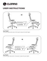
5.1Measuringcorrectly.............................29
5.2SettingDriveLockoutandLimitSwitches.............29
5.3Centerofgravity(CG)adjustments(forwardandaft)....30
5.3.1Adjustingcenterofgravity.....................31
5.3.2MountingpositionsforTDXSP2.................31
5.3.3MountingpositionsforStorm
4
..................32
6Chassis..........................................34
6.1Replacingtherearsuspensionstrut(Storm
4
)..........34
7Seat............................................35
7.1Remove/InstallSeatFrameShrouds.................35
7.2ReplacingSeatPansand/orSideRails...............35
7.3ReplacingPositioningSystemHardware.............36
7.4Replacingtiltactuator...........................36
7.5Replacinglifteractuator.........................36
7.6Removing/Installingseat.........................37
7.7Removing/Installingtiltmodule/lifter/tiltmodule......37
7.8AdjustingSeatDepth............................38
7.9AdjustingSeatWidthandBackrestWidth............38
7.10Adjustingseatheight(TDXSP2)...................39
7.11Settingpre-tilt................................39
7.12Replacingposturebelt..........................40
8Backrests........................................41
8.1ReplacingHighBackAssemblyorBackCover/Foam
Assembly...................................41
8.2Removing/InstallingtheMatrx®BackAssembly—Tilt
Systems....................................41
8.3Removing/InstallingtheMatrx®Back
Assembly—Recline............................42
8.4ReplacingBackCane............................42
8.5ReplacingSeatBackMountingHardware.............43
8.6ReplacingBackrestActuator.......................43
8.7ReplaceElanHeadrestAssembly...................44
8.8AdjustingBackrestHeight—ManualBackrest.........45
8.9AdjustingBackrestHeight—PoweredRecline.........50
8.10AdjustingExtendedShearReduction...............53
8.11Adjustingbackrestpreclineangle..................53
8.12AdjustingAngleofPresetBackrest.................54
8.13AdjustingfoaminsertsofHighBack................54
9Armrests........................................55
9.1ReplaceArmrestReceiver........................55
9.2ReplacingtheCantileverFlip-UpArmrest.............55
9.3Adjustingcantileverip-uparmrest.................55
9.4ReplacingtheCantileverSeatMountArmrest.........56
9.5UltraRailMountedFlipBackCantileverMaxx
Armrest....................................56
9.6InstallingMultiAxisUpperExtremitySupport
(MACES)....................................57
9.7AdjustarmpadwithMultiAxisUpperExtremity
Support(MACES).............................58
9.8InstallingElbowBlock...........................58
9.9AdjustingElbowBlock...........................58
9.10ArmPadInstallation/Adjustment..................59
9.11Installing/AdjustingTroughArmPad................60
9.12ReplacingHandPad............................60
9.13Adjustingtwopostreclinearmrest.................60
9.14Installing/AdjustingButtonsorT oggles..............61
10Legrests........................................62
10.1PivotPluslegrests.............................62
10.1.1SwingawayPivotPluslegrests.................62
10.1.2RemovingPivotPlusLegrests..................62
10.1.3AdjustingangleofPivotPluslegrests............62
10.1.4AdjustingWidth-andAngle-Adjustable
Footplate.................................63
10.1.5ReplacingActuatorofPoweredPivotPlus
Legrest...................................63
10.1.6ReplacingPivotPlusCalfPadAssembly...........63
10.1.7ReplacingFootplateRoller....................64
10.2Center-mountedlegrests—manuallyadjustable......64
10.2.1Installing/RemovingCenterMountedFootrest......64
10.2.2ReplacingCableReleaseFootrestBrace..........65
10.2.3Removing/installingcrossbraceofcenter-mounted
legrest...................................65
10.2.4Removingthelegrest........................65
10.2.5Settingtheangleofthelegrest................66
10.2.6SettingLengthofLegrest.....................66
10.2.7SettingAngleofFootPlate....................66
10.2.8Remove/InstallAdjustableCalfPadHardware......66
10.2.9SettingAngleandHeightofCalfPad............67
10.2.10ReplaceCenterBracketforManualCenter
MountFootrest............................67
10.3LNXlegrest..................................67
10.3.1Removing/installingcrossbraceofside-mounted
legrests..................................67
10.3.2ReplacingLNXpoweredcenter-mountedlegrest
withtelescopingfootboard....................67
10.3.3ReplacingIndependentMountingFootPlate
Hardwareand/orFootPlates..................68
10.3.4ReplacingFootPlatformAssembly..............69
10.3.5ReplacingIndividualCalfPad,CalfPadAssembly
orCover..................................69
10.3.6AdjustingBasicAngleofLNXLegrest............70
10.3.7Settingthelengthofthelegrest................70
10.3.8SettingAngleofFootPlate....................71
10.3.9Adjustingfootplatewidthofcenter-mounted
legrest...................................71
10.3.10SettingAngleofFootboard...................71
10.3.11SettingHeightandWidthofCalfPad...........71
10.4Vari-Ffootrest................................71
10.4.1Swivellingthefootrest/legrestoutwardand/or
removing.................................71
10.4.2Settingtheangle...........................72
10.4.3Settingtheendstopofthefootrest............72
10.4.4Adjustingthelengthofthefootrest.............73
10.5Vari-Alegrests................................73
10.5.1Swivellingthefootrest/legrestoutwardand/or
removing.................................73
10.5.2Settingtheangle...........................73
10.5.3Settingtheendstopofthelegrest..............74
10.5.4Adjustingthelengthofthelegrest..............75
10.5.5Adjustingthedepthofthecalfpad.............75
10.5.6Adjustingtheheightofthecalfpad.............75

Invacare®UltraLowMaxxbyMotionConcepts
10.5.7Unlockingandswivellingthecalfpadbackward
whenalighting.............................75
10.5.8Adjustingtheangle–adjustablefootplate.........75
10.5.9Adjustingtheangle–anddepth–adjustablefoot
plate....................................76
10.6ADMlegrests................................76
10.6.1Swivellingthelegrestoutwardand/orremoving....76
10.6.2Settingtheangle...........................76
10.6.3Adjustingthelengthofthelegrest..............76
10.6.4Adjustingthedepthofthecalfpad.............76
10.6.5Adjustingtheheightofthecalfpad.............77
10.6.6Unlockingandswivellingthecalfpadbackward
whenalighting.............................77
10.6.7Adjustingtheangle–adjustablefootplate.........77
10.6.8Adjustingtheangle–anddepth–adjustablefoot
plate....................................77
10.7Poweredelevatinglegrests(ADElegrests)............78
10.7.1Swivellingthelegrestoutwardand/orremoving....78
10.7.2Settingtheangle...........................78
10.7.3Adjustingthelengthofthelegrest..............78
10.7.4Adjustingthedepthofthecalfpad.............78
10.7.5Adjustingtheheightofthecalfpad.............78
10.7.6Unlockingandswivellingthecalfpadbackward
whenalighting.............................79
10.7.7Adjustingtheangle–adjustablefootplate.........79
10.7.8Adjustingtheangle–anddepth–adjustablefoot
plate....................................79
11PositioningOptions...............................80
11.1Hipsupportwithquickrelease...................80
11.2LateralTrunkSupportAdjustments.................81
11.3Headrests...................................81
11.3.1Adjustingtheheadrest.......................81
11.3.2InstallingheadrestadapterforEliteandHigh
Backs....................................82
11.3.3Auto–styleheadrestset-upandinstallation........82
11.3.4AdjustingElanHeadrestHardware..............82
11.3.5Adjustingmulti-axisheadresthardware...........83
12PrimaryRemotes.................................85
12.1AdjustmentPossibilityforRemote.................85
12.1.1AdjustingRemoteHeight(onlyforSwing–Away
RemoteSupports)...........................85
12.1.2AdjustingRemoteOffset......................85
12.1.3InstallingStandardRemoteHolderforLiNX
Remotes..................................85
12.1.4InstallingSwing-AwayRemoteHolderforLiNX
Remotes..................................85
12.2AdjustingSwing-AwayDisplayHolder...............86
12.3QuadLink...................................86
12.3.1InstallingRemoteontoQuadLink(untilFebruary
2017)....................................86
12.3.2ReversingMountingPositionofRemote(until
February2017).............................87
12.3.3Securingtheremotecable....................88
12.3.4InstallingLiNXRemoteontoQuadLink...........88
12.3.5ReversingMountingPositionofRemote(asof
February2017).............................88
12.3.6Adjustingremoteheight......................89
12.3.7Adjustingremoteposition....................89
12.3.8AdjustingLockTension.......................89
12.4NucleusMidlineHolder.........................90
12.4.1InstallingNucleusMidlineHolder...............90
12.4.2AdjustingDepthofMidlineHolder..............90
12.4.3AdjustingHeightofNucleusMidlineHolder.......90
12.4.4AdjustingJoystick/DisplayPositiononNucleus
MidlineHolder.............................90
13SecondaryInputs—User...........................92
13.1AdjustingManualChinControl....................92
13.1.1AdjustingExtremityControlJoystick.............92
13.1.2AdjustingEggSwitch........................92
13.2AdjustingHeadArray...........................92
13.3AdjustingSipandPuffHeadArray.................92
13.4AdjustingSwing-AwayMechanism.................93
13.5ReplacingLipswitch............................93
14SecondaryInputs—Attendant.......................94
14.1InstallingBracketforAttendantRemoteHolder.......94
14.2InstallingClampforDLX-ACU200RemoteHolderon
ManualBackrest..............................94
15AuxiliaryModules................................95
15.1ReplacingInputModuleDLX-IN500................95
15.2ReplacingOutputModuleDLX-OUT500.............95
15.3ReplacingActuatorModuleDLX-ACT400.............96
4
1586649-F

General
1General
1.1Introduction
Thisdocumentcontainsimportantinformationabout
assembly,adjustmentandadvancedmaintenanceofa
productcomponent.Toensuresafetywhenhandlingthe
component,readthisdocument,theservicemanualsof
thebaseproductandadditionalcomponents,andtheuser
manualscarefullyandfollowthesafetyinstructions.
ThecomponentitselfdoesnotbearaCEmarking,butitis
partofaproductthatcomplieswiththerespectivevalid
regulationsconcerningmedicaldevices.Thecomponents
isthereforecoveredbytheCEmarkingoftheproduct.
FindtheusermanualonInvacare’swebsiteorcontact
yourInvacarerepresentative.Seeaddressesattheend
ofthisdocument.
Invacarereservestherighttoalterproductspecications
withoutfurthernotice.
Beforereadingthisdocument,makesureyouhavethe
latestversion.YoundthelatestversionasaPDFonthe
Invacarewebsite.
Forpre-saleanduserinformation,seetheusermanual.
Formoreinformationabouttheproduct,forexample
productsafetynoticesandproductrecalls,contactyour
Invacarerepresentative.Seeaddressesattheendofthis
document.
1.2GeneralInformation
Serviceandmaintenanceworkmustbecarriedouttaking
thisdocumentintoaccount.
Itisimperativethatyouobservesafetyinformation.
Informationaboutoperationoraboutgeneralmaintenance
andcareworkontheproductshouldbetakenfrom
servicemanual.
Assemblyofaccessoriesmightnotbedescribedinthis
document.Refertothemanualdeliveredwiththe
accessory.Additionalmanualscanbeorderedfrom
Invacare.Seeaddressesattheendofthisdocument.
Youcanndinformationaboutorderingsparepartsin
thesparepartscatalogue.
SparepartsmustmatchoriginalInvacareparts.Onlyuse
sparepartswhichhavebeenapprovedbyInvacare.
Theproductmayonlybemaintainedandoverhauledby
qualiedpersonnel.
Theminimumrequirementforservicetechniciansis
suitabletraining,suchasinthecycleororthopedic
mechanicselds,orsufcientlylong-termjobexperience.
Experienceintheuseofelectricalmeasuringequipment
(multimeters)isalsoarequirement.SpecialInvacare
trainingisrecommended.
Alterationstothemobilitydevicewhichoccurasaresult
ofincorrectlyorimproperlyexecutedmaintenanceor
overhaulworkleadtotheexclusionofallliabilityonthe
sideofInvacare.
Ifyouhaveanyproblemsorquestionscontactyour
provider .
1.3NotesonShipping
•Ifthemobilitydevicehastobeshippedbacktothe
manufacturerformajorrepairs,youshouldalways
usetheoriginalpackagingfortransport.
•Pleaseattachaprecisedescriptionofthefault.
1.4SymbolsinThisManual
Symbolsandsignalwordsareusedinthismanualand
applytohazardsorunsafepracticeswhichcouldresultin
personalinjuryorpropertydamage.Seetheinformation
belowfordenitionsofthesignalwords.
WARNING
Indicatesahazardoussituationthatcould
resultinseriousinjuryordeathifitisnot
avoided.
CAUTION
Indicatesahazardoussituationthatcould
resultinminororslightinjuryifitisnot
avoided.
IMPORTANT
Indicatesahazardoussituationthatcould
resultindamagetopropertyifitisnot
avoided.
Tips
Givesusefultips,recommendationsand
informationforefcient,trouble-freeuse.
Tools
Identiesrequiredtools,componentsand
itemswhichareneededtocarryoutcertain
work.
1.5ImagesinThisManual
Thedetailedimagesinthismanualaregivenmarksto
identifyvariouscomponents.Componentmarksintext
andoperationalinstructionsalwaysrelatetotheimage
directlyabove.
1.6SystemIdentication
EachMotionConceptsseatingsystemisidentiedby
auniqueserialnumber,whichallowsustotracethe
productionhistoryofthesystemandbetterequips
ustoaddressanyserviceissuesthatmayoccurover
thelifetimeoftheproduct.Thelocationoftheserial
numberidenticationplatevariesdependingonthetype
ofpositioningsysteminstalled.Therearetwopossible
mountinglocationsasindicatedintheimagesbelow.
1586649-F5

Invacare®UltraLowMaxxbyMotionConcepts
1.7Abbreviations
Abbreviation
Meaning
CG
=
CenterofGravity
DLO
=
DriveLockout
ESR
=
ExtendedShearReduction
PES
=
PowerElevatingSeat
PPS
=
PowerPositioningSystem
STF
=
Seat-To-FloorHeight
61586649-F

Safety
2Safety
2.1SafetyandFittingInstructions
Thesesafetyinstructionsareintendedtopreventaccidents
atwork,anditisimperativethattheyareobserved.
Beforeanyinspectionorrepairwork
•Readandobservethisrepairmanualandthe
associatedusermanual.
•Observetheminimumrequirementsforcarryingout
thework(see1.2GeneralInformation,page5).
PersonalSafetyEquipment
Safetyshoes
Themobilitydevice,andsomeofitscomponents,arevery
heavy.Thesepartscanresultininjuriestothefeetifthey
areallowedtodrop.
•Wearstandardizedsafetyshoesduringallwork.
Eyeprotection
Itispossiblethatbatteryacidcanbedischargedwhen
workingondefectivebatteriesorwhenhandlingbatteries
improperly.
•Alwaysweareyeprotectionwhenworkingonany
defectiveorpossiblydefectivebatteries.
Safetygloves
Itispossiblethatbatteryacidcanbedischargedwhen
workingondefectivebatteriesorwhenhandlingbatteries
improperly.
•Alwayswearacid-proofsafetygloveswhenworking
onanydefectiveorpossiblydefectivebatteries.
GeneralSafetyInformationandInformationAboutFitting
/Removal
DANGER!
RiskofDeath,SeriousInjury,orDamage
Lightedcigarettesdroppedontoanupholstered
seatingsystemcancauseareresultingin
death,seriousinjury,ordamage.Mobility
deviceoccupantsareatparticularriskofdeath
orseriousinjuryfromtheseresandresulting
fumesbecausetheymaynothavetheabilityto
moveawayfromthemobilitydevice.
–DONOTsmokewhileusingthismobility
device.
WARNING!
RiskofSeriousInjuryorDamage
Storingorusingthemobilitydevicenearopen
ameorcombustibleproductscanresultin
seriousinjuryordamage.
–Avoidstoringorusingthemobilitydevice
nearopenameorcombustibleproducts.
CAUTION!
Riskofcrushing
Variouscomponentssuchasthedriveunit,
batteries,seatetcareveryheavy.Thisresults
ininjuryhazardstoyourhands.
–Notethehighweightofsomecomponents.
Thisappliesespeciallytotheremovalofdrive
units,batteriesandtheseat.
CAUTION!
Injuryhazardifthemobilitydevicestarts
movingunintentionallyduringrepairwork
–Switchthepowersupplyoff(ON/OFFkey).
–Engagethedrive.
–Beforeliftingup,securethemobilitydevice
byusingchockstoblockthewheels.
CAUTION!
Fireandburnhazardduetoelectrical
short-circuit
–Themobilitydevicemustbecompletely
switchedoffbeforeremovalof
voltage-carryingcomponents!Todo
this,removethebatteries.
–Avoidshort-circuitingthecontacts
whencarryingoutmeasurementson
voltage-carryingcomponents.
CAUTION!
Riskofburnsfromhotsurfacesonthemotor
–Allowthemotorstocooldownbefore
commencingworkonthem.
CAUTION!
Injuryhazardandriskofdamagetomobility
deviceduetoimproperorincomplete
maintenancework
–Useonlyundamagedtoolsingoodcondition.
–Somemovingpartsaremountedinsockets
withPTFEcoating(Teon™).Nevergrease
thesesockets!
–Neveruse"normal"nutsinsteadof
self-lockingnuts.
–Alwaysusecorrectly-dimensionedwashers
andspacers.
–Whenreassembling,alwaysreplaceanycable
tieswhichwerecutduringdismantling.
–Aftercompletingyourwork/beforerenewed
start-upofthemobilitydevice,checkall
connectionsfortighttting.
–Aftercompletingyourwork/beforerenewed
start-upofthemobilitydevice,checkallparts
forcorrectlocking.
–Onlyoperatethemobilitydevicewiththe
approvedtyrepressures(seetechnicaldata).
–Checkallelectricalcomponentsforcorrect
function.Notethatincorrectpolaritycan
resultindamagetothecontrolsystem.
–Alwayscarryoutatrialrunattheendof
yourwork.
CAUTION!
Riskofinjuryanddamagetoproperty,ifthe
maximumspeedreductiononawheelchair
withalifterdoesnotfunctioncorrectly
Thewheelchair’scontrolunitmustreducethe
maximumpossiblespeedassoonasthelifter
israised.
–Testthemaximumspeedreductionfor
correctfunctionafteranymaintenancework
ormodicationstothewheelchair .
1586649-F
7

Invacare®UltraLowMaxxbyMotionConcepts
CAUTION!
Anychangestothedriveprogramcanaffect
thedrivingcharacteristicsandthetipping
stabilityofthemobilitydevice
–Changestothedriveprogrammayonlybe
carriedoutbytrainedInvacareproviders.
–Invacaresuppliesallmobilitydeviceswitha
standarddriveprogramex-works.Invacare
canonlygiveawarrantyforsafemobility
devicedrivingbehavior-especiallytipping
stability-forthisstandarddriveprogram.
Markallcurrentsettingsforthemobilitydevice
(seat,armrests,backrestetc.),andtheassociated
cableconnectingplugs,beforedismantling.This
makesreassemblyeasier.Allplugsarettedwith
mechanicallockswhichpreventreleaseofthe
connectingplugsduringoperation.Toreleasethe
connectingplugsthesafetylocksmustbepressed
in.Whenreassemblingensurethatthesesafety
locksarecorrectlyengaged.
81586649-F

Overview
3Overview
3.1Components
3.1.1OverviewofSeatingSystem
Fig.3-1
A
Backrest,see3.1.2BackrestStyles,page9
B
Armrest,see3.1.3ArmrestStyles,page10
C
Cushion
D
Seatplate
E
Siderail
F
Remotebracket,see3.1.4RemoteBrackets,
page11
G
Remotebracketforattendant,see3.1.4
RemoteBrackets,page11
3.1.2BackrestStyles
TheUltraLowMaxxseatisavailablewithdifferentbackreststyles.
1586649-F9

Invacare®UltraLowMaxxbyMotionConcepts
BackrestFrameBackrestStyle
Fig.3-2ManualRecline
Fig.3-3StandardRehabBack
Fig.3-5HighBack
Fig.3-4PoweredReclinewithESR
Fig.3-6MatrxBacks
3.1.3ArmrestStyles
TheUltraLowMaxxseatisavailablewithdifferentarmreststyles.Forremotebracketsthatcanbemountedtoarmrest,
see3.1.4RemoteBrackets,page11.
ForPoweredReclineForManualRecline
Fig.3-7TwoPostRecline
Fig.3-8BackpostMountedFlipBackCantilever
Fig.3-9UltraRailMountedFlipBack
CantileverMaxx
Armpadstyles
AllUltraLowMaxxarmrestsareavailablewiththefollowingarmpads:
101586649-F

Overview
DeskArmpadFullLengthArmpadErgonomicArmtroughFlatHandPad
Fig.3-10
Fig.3-11
Fig.3-12
Fig.3-13
3.1.4RemoteBrackets
UltraLowMaxxcanbettedwithdifferentbracketsforremotes:
•PrimaryRemotesforUsers,page11
•SecondaryInputsforUsers,page12
•RemotesforAttendant,page12
PrimaryRemotesforUsers
Remotesforthewheelchairuserareinstalledataslotatthearmrestoronnucleusmidlineholder.
StandardwithSupportTubeStandardwithSwing-AwayBracket
Fig.3-14
Fig.3-15
QuadLinkREM500Swing-AwayDisplayHolder
Fig.3-16
Fig.3-17
1586649-F
11

Invacare®UltraLowMaxxbyMotionConcepts
NucleusMidlineHolderforREM500
Fig.3-18
Fig.3-19
UltraLowMaxxwithnucleusmidlineholdercancarryadditionalbrackets,remotesandswitches.Anadapterisneeded
toinstallnucleusmidlineholdertoslotatthearmrest.
SecondaryInputsforUsers
NucleusMidlineHolder
Fig.3-21
Fig.3-22
Fig.3-20
Fig.3-23
SupportTube
Fig.3-25
Fig.3-24
Fig.3-26
RemotesforAttendant
Remotebracketforthewheelchairattendantisinstalledatthepushbaroratthepushhandlesatthebackrestframe
ofthepowerwheelchair.
12
1586649-F

Overview
AttendantRemoteBracketforPrimary
Remotes
AttendantRemoteBracketfor
SecondaryInputs
AttendantRemoteBracketforIDC
Fig.3-27
Fig.3-28
Fig.3-29
Remotebracketcanbemountedinavarietyofpositions.
3.1.5MountingPositionsofLiNXModules
Thischapteronlyshowsthemountingpositionsofmodulesinstalledonthebackrest.Youndmoreinformationabout
thefollowingcomponentsintheLiNXservicemanual:
•Remotemodules
•ASLcomponents
•Powermodules
•LiNXseatingmodulesandinterfaces
•Poweredseatingaccessories
•Powermodulemounting
•MountingpositionsofpowermodulesandDLX-ACT400onthewheelchair
Fig.3-30ManualBackrest
Fig.3-31PoweredBackrest
A
DLX-OUT500
Outputmodule
B
DLX-IN500
Inputmodule
C
GLM-CONX4
Busexpansionblock
D
DLX-ACT400
Actuatormodule
3.1.6LiNXWiringDiagrams
WiringdiagramsforLiNXaredescribedintheLiNXservice
manual.
3.2TighteningTorques
CAUTION!
Riskofdamagetomobilitydevicedueto
improperlytightenedscrews,nutsorplastic
connections.
–Alwaystightenscrews,nutsetc.tothestated
tighteningtorque.
–Onlytightenscrewsornutswhicharenot
listedherengertight.
1586649-F13

Invacare®UltraLowMaxxbyMotionConcepts
Thetighteningtorquesstatedinthefollowinglistare
basedonthethreaddiameterforthenutsandboltsfor
whichnospecicvalueshavebeendetermined.Allvalues
assumedryandde-greasedthreads.
ThreadTighteningTorquein
Nm±10%
M43Nm
M5
6Nm
M610Nm
M825Nm
M1049Nm
M1280Nm
M14120Nm
M16180Nm
3.3Imperialtometricconversionchart
Youcanusethischartasanorientationtondtheright
toolsize.
IMPERIALMETRIC
inch
mm
5/64
1.9844
3/32
2.3813
7/64
2.7781
1/8
3.1750
9/64
3.5719
5/32
3.9688
11/64
4.3656
3/16
4.7625
13/64
5.1594
7/32
5.5563
15/64
5.9531
1/4
6.3500
17/64
6.7469
9/32
7.1438
19/64
7.5406
5/16
7.9375
21/64
8.3344
11/32
8.7313
23/64
9.1281
3/8
9.5250
25/64
9.9219
13/32
10.3188
IMPERIALMETRIC
inch
mm
27/64
10.7156
7/16
11.1125
29/64
11.5094
15/32
11.9063
31/64
12.3031
1/2
12.7000
33/64
13.0969
17/32
13.4938
35/64
13.8906
9/16
14.2875
37/64
14.6844
19/32
15.0813
39/64
15.4781
5/8
15.8750
41/64
16.2719
21/32
16.6688
43/64
17.0656
11/16
17.4625
45/64
17.8594
23/32
18.2563
47/64
18.6531
3/4
19.0500
49/64
19.4469
25/32
19.8438
51/64
20.2406
13/16
20.6375
53/64
21.0344
27/32
21.4313
55/64
21.8281
7/8
22.2250
3.4ACS2MountingPositionsand
WiringDiagrams
3.4.1MountingPositionsofACS2Modules
Thischapteronlyshowsthemountingpositionsofmodules
installedonthebackrest.Youndinformationabout
othercomponentsintheservicemanualofthepower
wheelchair.
14
1586649-F


Invacare®UltraLowMaxxbyMotionConcepts
3.4.2WiringdiagramsUltraLowMaxxwithTDXSP2
Wiringdiagramtilt/recline(TDXSP2)
161586649-F


Invacare®UltraLowMaxxbyMotionConcepts
Wiringdiagramtilt/reclineandattendantcontrol(TDXSP2)
181586649-F


Invacare®UltraLowMaxxbyMotionConcepts
3.4.3WiringdiagramsUltraLowMaxxwithStorm
4
Wiringdiagramtilt/recline(Storm
4
)
201586649-F
/