Anova TAN3280FM Assembly Instructions Manual
- Type
- Assembly Instructions Manual

!
anovafurnishings.com
888.535.5005 tel
TOOLS NEEDED:
• 5/32" Allen wrench
• 1/4" Allen wrench
• 3/16" Wire pull rod
• 5/16" Open-end or
box-end wrench
Assembly Instructions
Tandem Contour Benches
TAN3284P-4'
TAN3284T-4'
TAN3284FM-4'
TAN3284MR-4'
TAN3280FM-6'
TAN3280MR-6'
TAN3280P-6'
TAN3280T-6'
-
-
PERSPECTIVE
TOTEM
-
-
FRACTURED MOVEMENT
MOUNTAIN RANGE
&
&
&
&
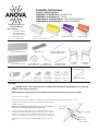
BENCH COMPONENTS: Pattern may vary on the bench seat and backrest panels.
ASSEMBLY HARDWARE: All hardware is stainless steel.
(1) Bench Seat
ASSEMBLY:
Inspect the shipping container contents for damage and to determine that all components and hardware are present.1.
2. Lay all parts on a so work surface or on the shipping packaging to prevent
damage to the nish.
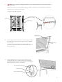
3. Locate one of the mounting anges and one of LED light xtures. Mount
the light xture to the ange by inserting two 6-32 x 3/8" hex head bolts
through the mounting holes. Place two 6-32 x 5/16 Nylock nuts on the ends
of the screws and tighten them with the 5/16" open-end or box-end wrench.
Repeat this process to install the remaining LED light xture to the other
ange.
NOTE: Before assembling the nuts to the bolts, it is recommended that a
light oil or petroleum jelly be applied to the screw threads.
(1) Le End
Casting
(1) Right End
Casting
(7) 1/4"-20 x 5/8"
Allen Head Screws
Perspective Mountain RangeTotem Fractured Movement
(2) Optional
Mounting Flanges
(1) Optional Back
Panel Wire Cover
(1) Optional Bench Seat
Aluminum Wire Cover
(2 or 3) Optional
LED Light Fixtures
(4) 6-32 x 3/8"
Hex Head Bolts
(4) 6-32 x 5/16"
Nylock Nuts
(8) 5/16"-18 x 1"
Allen Head Screws
(4) 5/16" Flat
Washers
Mounting Flange
LED Light
6-32 x 3/8"
Hex Head Bolt
6-32 x 5/16"
Nylock Nut
(1) Rear Backrest Panel
(1) Front Backrest Panel
(3) 1/4" Flat
Washers
CAUTION: Steps 3 – 10 are applicable for the assembly of optional 2-light and 3-light LED kits. For a 3-light LED
kit, include steps A – G on page 4.
NOTE: LED light kit components must be assembled and mounted to the bench before the panel assemblies.
1
This is a two-person assembly.
4' Benches will be available soon.
Additional Hardware Not
Included with Purchase
(2) Heat Shrink Crimp

2
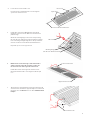
Bench Seat
Bench Seat Aluminum Wire Cover
4. Locate the bench seat and wire cover.
Insert the bench seat aluminum wire cover through the
square slots on the bench seat.
1/4"-20 x 5/8" Allen Head Screw
Mounting Flange
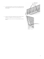
Wire Leads
Take the wires from the light xture that is mounted to the le
end of the bench and measure approximately 2 feet of wire from
the xture, then cut and save the excess wire. It will be needed
in step 9.
7.
Pull the wires leads of the LED light xture through the
middle hole of the bench seat. Make sure all of the slack is
pulled through.
Mount the mounting ange to the bench seat by inserting
two 1/4"-20 x 5/8" Allen head screws through the mounting
holes of the ange and tightening them to the pre-installed
rivet nuts on the bench seat with the 5/32" Allen wrench.
Repeat this process on the opposite side.
5.
NOTE: The wire leads run through a small channel with a
stainless steel tube in the le end casting so make sure
the wire leads run from the right side to the le side.
Pull the wire leads from the right end of the bench seat
through the aluminum wire cover using the 3/16" wire pull
rod.
6.
Connected wire leads
Square Slots
Le end of the bench
Right end of the bench

3
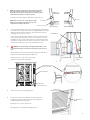
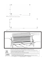
Locate the trimmed spare wires from step 7 and guide them through the
hole in the back of the leg of the le end casting by pulling them through
with the 3/16" wire pull rod until there is approximately 2 feet of wire
remaining out of the seat access hole.
Strip each wire end of insulation until approximately a 1/4" of bare wire
is exposed. Using the heat shrink crimps, secure one wire from each of
the LEDs in to one end of the crimp and insert one of the wires that runs
through the casting into the other. Then use a heat gun to seal the heat
shrink crimp. Repeat the process for the remaining loose wires.
9.
NOTE: The le end casting has two threaded holes about half
way up the back leg and also has a channel in the bottom of
the back leg for the wire to run through. The right leg only has
one threaded hole and does not have a channel.
Locate the end castings and place them next to the bench seat.
8.
!
10. Caution: To avoid pinching or damaging the LED wire, use the
compartment built into each of the bench castings to tuck any excess
wire.
Mount the bench seat to the end casting by inserting two 5/16"-18 x 1"
Allen head screws and through the mounting holes.
Repeat this process on the on the opposite side.
Tighten all of the hardware nger tight.
11. Turn the bench over into an upright position.
Le End Casting
Bench Seat
5/16"-18 x 1"
Allen Head Screw
Compartment for
the excess wires.
Le End Casting Right End Casting
Two holes
Seat access hole
One hole
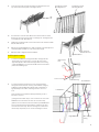
12. Insert two of the 5/16"-18 x 1" Allen head screws through the
mounting holes of the front backrest panel and the right end
casting and tighten them nger tight.
Repeat this process on the opposite side.
Then tighten the screws with the 1/4" Allen wrench.
5/16"-18 x 1"
Allen Head Screw
Front Backrest
Panel
NOTE: Refer to steps A – G on page 4 if the 3-light
LED kit is being installed. Return to steps 13- 17 to
complete the assembly of the bench.
THIS DRAWING IS FOR PROTOTYPE OR TOOLING
USE ONLY. DO NOT USE FOR PRODUCTION.
REVISIONS
REV.
DESCRIPTION
DATE
6" iconic bench
A
TAN3280P
SHEET 1 OF 1
1:3
1/15/2018
REV
DWG. NO.
B
SIZE
TITLE:
PRINT IS FOR FABRICATION ONLY. ALL SURFACES
MAY EXPAND BY .125± .0625 DURING COATING.
ALL DIMENSIONS ARE IN INCHES AND ALL ANGLES
OR BENDS ARE 90º UNLESS OTHERWISE SPECIFIED
DO NOT SCALE DRAWING
211 North Lindbergh Blvd.
St. Louis, MO 63141
888.535.5005 tel
314.754.0835 fax
anovafurnishings.com
THIS DRAWING AND ALL THE INFORMATION CONTAINED HEREIN IS THE PROPERTY OF
ANOVA™. DO NOT USE OR COPY WITHOUT WRITTEN PERMISSION.
THIS DRAWING IS CONFIDENTIAL AND IS SUBJECT TO RETURN ON DEMAND.
THIRD ANGLE PROJECTION
DRAWN
DATE
R. Patterson
TOLERANCES UNLESS NOTED:
X ± 1 X.X ± .5 X.XX ± .25 X.XXX ± .125
X.XXXX ± .0625 X.XXXXX ± .03125
X.XXXXXX ± .015625 ANGULAR ± 1°
SCALE
A A
B B
4
4
3
3
2
2
1
1
Right LED wires
Le LED wires
Wires through
casting

4
13. Locate the rear backrest panel and slide its mounting brackets over
top of the front backrest panel's mounting brackets.
Front Backrest Panel
Mounting Bracket
Rear Backrest Panel
Mounting Bracket
14. Insert the three 1/4"-20 x 5/8" Allen head screws and three 1/4" at
washers into the rear backrest panel's mounting holes. Then tighten the
screws with the 5/32" Allen wrench.
15. Tighten the remaining 5/16" screws on the bottom side of the bench with
the 1/4" Allen wrench.
17. Aer two weeks, retighten all of the hardware.
16. Aer the bench with LED xtures is fully assembled, approximately 4 feet
of lead wire will be available to route to the power supply.
1/4"-20 X 5/8"
Allen Head Screw
1/4" Flat Washer
3-LED Light Assembly
Locate the 3rd LED xture and guide the wires through the wire
channel hole and out of the seat access hole. Be sure to leave
approximately 40" of wire between the light xture and casting
so that this LED xture can reach the middle of the front backrest
panel in the following steps.
A.
Right LED wires
(i)
(ii)
Le LED wires
Back LED wires
Wires through
casting
B. Locate the trimmed spare wires from step 7 and guide them
through the hole in the back of the leg of the le end casting by
pulling them through with the 3/16" wire pull rod until there is
approximately 2 feet of wire remaining out of the seat access
hole.
Strip each wire end of insulation until approximately a 1/4" of
bare wire is exposed.
(i) Using the heat shrink crimps, secure one wire from each of the
LED xtures from the bench seat into one end of the crimp.
(ii) Next, insert one wire from the front backrest panel LED xture
and one of the wires that run through the casting into the other
end of the heat sink crimp. Then use a heat gun to seal the heat
shrink crimp. Repeat the process for the remaining loose wires.
Le End Casting
Wire Channel
Hole
Seat access hole

5
5/16"-18 x 1"
Allen Head Screw
Front Backrest
Panel
Insert two of the 5/16"-18 x 1" Allen head screws through the mounting
holes of the front backrest panel and the right end casting and tighten
them nger tight.
Insert one of the 5/16"-18 x 1" Allen head screws through the top
mounting holes of the front backrest panel and the le end casting and
tighten it nger tight.
Mount the LED light xture to the back panel mounting bracket by
inserting two 6-32 x 3/8" hex head bolts through the mounting holes.
Place two 6-32 x 5/16" nylock nuts on the ends of the screws and tighten
them with the 5/16" open-end or box-end wrench.
D.
E.
6-32 x 3/8" Hex Head Bolt
6-32 x 5/16" Nylock Nut
LED Light Fixture
!
C. Caution: To avoid pinching or damaging the LED wire, use the compartment built into each of the bench castings to
tuck any excess wire.
Mount the bench seat to the end casting by inserting two 5/16"-18 x 1" Allen head screws and through the mounting holes.
Repeat this process on the on the opposite side.
Tighten all of the hardware nger tight.
Le End Casting
Bench Seat
Compartment for
the excess wires.
THIS DRAWING IS FOR PROTOTYPE OR TOOLING
USE ONLY. DO NOT USE FOR PRODUCTION.
REVISIONS
REV.
DESCRIPTION
DATE
6" iconic bench
A
TAN3280P
SHEET 1 OF 1
1:3
1/15/2018
REV
DWG. NO.
B
SIZE
TITLE:
PRINT IS FOR FABRICATION ONLY. ALL SURFACES
MAY EXPAND BY .125± .0625 DURING COATING.
ALL DIMENSIONS ARE IN INCHES AND ALL ANGLES
OR BENDS ARE 90º UNLESS OTHERWISE SPECIFIED
DO NOT SCALE DRAWING
211 North Lindbergh Blvd.
St. Louis, MO 63141
888.535.5005 tel
314.754.0835 fax
anovafurnishings.com
THIS DRAWING AND ALL THE INFORMATION CONTAINED HEREIN IS THE PROPERTY OF
ANOVA™. DO NOT USE OR COPY WITHOUT WRITTEN PERMISSION.
THIS DRAWING IS CONFIDENTIAL AND IS SUBJECT TO RETURN ON DEMAND.
THIRD ANGLE PROJECTION
DRAWN
DATE
R. Patterson
TOLERANCES UNLESS NOTED:
X ± 1 X.X ± .5 X.XX ± .25 X.XXX ± .125
X.XXXX ± .0625 X.XXXXX ± .03125
X.XXXXXX ± .015625 ANGULAR ± 1°
SCALE
A A
B B
4
4
3
3
2
2
1
1

6
F. Locate the back panel wire cover and insert its from a high angle into the
LED mounting bracket's slot. Once it is in the slot lower it down onto the
back rest panel.
G. Mount one of the 5/16"-18 x 1" Allen head screws to the le end casting
aligning the screw with the curve on the back panel wire cover.
Then tighten all of the screws on the rear back panel with the 1/4" Allen
wrench.
5/16"-18 x 1"
Allen head screw
LED Mounting
Bracket Slot

1/25/2018 Copyright 2018 ANOVA® Made in USA. 7
Note: Please contact Customer Care at 1-866-797-1761 when ordering replacement parts.
Tandem Assembly and Replacement Parts
Mounting Flange
LED Light Fixture
Bench Seat
Le End Casting
Front Backrest Panel
Rear Backrest Panel
Right End Casting
O 0.50"
70.62"
Tandem 6' Contour Bench Foot Mount
21.75"
21.75"
47.44"
Tandem 4' Contour Bench Foot Mount
Wire Cover
O 0.50"
-
 1
1
-
 2
2
-
 3
3
-
 4
4
-
 5
5
-
 6
6
-
 7
7


Anova TAN3280FM Assembly Instructions Manual
- Type
- Assembly Instructions Manual
Ask a question and I''ll find the answer in the document
Finding information in a document is now easier with AI
Related papers
-
Anova CE18J90T Assembly Instruction
-
-
-
-
-
-
-
-
-
Other documents
-
 Rotorlight Anova User manual
-
Polaris 2008 sportsman x2 User manual
-
Polaris Sportsman 800 EFI User manual
-
Cub Cadet Domestic Series 7000 User manual
-
 Sportsman Masters 227 Bay Boat Owner's manual
-
 Sportsman Masters 207 Bay Boat Owner's manual
-
 Sportsman Masters 267 Bay Boat Owner's manual
-
Rikon Power Tools 30-217 User manual
-
 South bend SB1002 Owner's manual
-
 Sportsman Masters 267 Bay Boat Owner's manual


