Page is loading ...

Operative technique
EasyFuse
Dynamic compression system
™

2
EasyFuse™ | Operative technique
Introduction 3
Indications and contraindications 4
Operative technique 5
Mid/hindfoot surgical technique 5
4-Leg surgical technique 8
Removal and reinsertion 11
Procedural sizing chart 12
Ordering information 13
Table of contents
EasyFuse™
Dynamic compression system
Proper surgical procedures and techniques are the
responsibility of the medical professional. The following
guidelines are furnished for information purposes only.
Each surgeon must evaluate the appropriateness of
the procedures based on his or her personal medical
training and experience. Prior to use of the system,
the surgeon should refer to the product package insert
for complete warnings, precautions, indications,
contraindications and adverse effects. Package inserts
are also available by contacting the manufacturer.
Contact information can be found on the back of this
surgical technique and the package insert is available
on the website listed.
Acknowledgments:
Surgeon design team – The EasyFuse dynamic compression system was developed in conjunction with:
John R. Clements, DPM (Roanoke, VA), Kent Ellington, MD (Charlotte, NC), Carroll Jones, MD (Charlotte, NC),
John S. Lewis, Jr., MD (Louisville, KY)

3
EasyFuse™ | Operative technique
Indications and contraindications
Indications
The EasyFuse dynamic compression system is intended
to be used for fracture xation, osteotomy xation, and
joint arthrodesis of the foot and ankle.
Contraindications
There are no product specic contraindications.
Introduction
15 x 12 x 12
4.1 x 1.5 x 2.5
15 x 15 x 15
4.1 x 1.5 x 2.5
15 x 20 x 20
4.1 x 1.5 x 2.5
18 x 15 x 15
4.1 x 1.5 x 2.5
18 x 20 x 20
4.1 x 1.5 x 2.5
18 x 25 x 25
4.1 x 1.5 x 2.5
20 x 15 x 15
5.5 x 1.5 x 2.5
20 x 20 x 20
5.5 x 1.5 x 2.5
20 x 25 x 25
5.5 x 1.5 x 2.5
25 x 20 x 20
5.5 x 1.5 x 2.5
25 x 25 x 25
5.5 x 1.5 x 2.5
25 x 20 x 20 x 20 x 20
5.5 x 1.5 x 2.5
30 x 20 x 20 x 20 x 20
5.5 x 1.5 x 2.5
30 x 12 x 14 x 16 x 16
5.5 x 1.5 x 2.5
30 x 14 x 16 x 18 x 18
5.5 x 1.5 x 2.5
Dimensions in millimeters (mm)
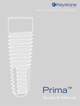
Legend
1
1 x 2 x 3
A x B x C
2 3
AB
C
EasyFuse dynamic compression system is an internal xation system intended for fractures, osteotomies, and joint
arthrodesis of the midfoot and hindfoot. The system is provided as a single-use sterile pack comprising of a bone staple
implant and select instruments for implantation. Multiple implants sizes are available consisting of two-leg and four-leg
variants with features such as low-prole and wide bridges, as well as multiple leg lengths. Additional instruments are
provided in separate, single-use sterile packs. The staple is composed of nickel-titanium (nitinol) alloy per ASTM F2063.
EasyFuse implants are provided pre-loaded on a single-use disposable cartridge. This cartridge is then attached to an
inserter creating the assembly used to implant the staple. The implant is designed to provide sustained compression
to facilitate bony fusion.

4
EasyFuse™ | Operative technique
Operative technique
Mid/Hindfoot
surgical technique
Step 1: Prepare fusion site
Create the osteotomy and/or prepare the fusion site
needed to implant EasyFuse.
Step 2: Size
Place the Universal Drill Guide perpendicular across
the xation site to determine the appropriate implant
size. Rotate the knob clockwise and select the preferred
staple size. Notice the distance between drill holes will
change as the knob is rotated to each size.
Universal Drill Guide
Step 3: Drill
Use the Drill to create a pilot hole in the bone. Use the
laser markings on the Drill to measure the drill depth.
Prior to drilling any additional holes, place a
corresponding Locator Pin in the rst hole through the
drill guide.
Drill
Locator Pin

5
EasyFuse™ | Operative technique
Step 4: Prepare inserter
Place the Universal Implant Inserter into its unlocked
position by lifting the lever up.
Assemble the selected implant Cartridge onto the
Universal Inserter by aligning the tabs on the implant
Cartridge with the grooves of the Universal Inserter
and rotating clockwise until locked.
Proceed to press the lever of the Universal Inserter
down to its locked position to outwardly displace the
legs of the EasyFuse implant.
Universal Inserter
Implant Cartidge
Step 5: Insert implant
Remove the Locating Pins and Drill Guide before
inserting the implant.
Position the legs of the EasyFuse over the pilot holes
and advance the implant into the holes by hand until
fully seated.

6
EasyFuse™ | Operative technique
Step 6: Remove inserter
Unlock the Universal Implant Inserter from the implant
by moving the inserter lever to its unlocked position.
Slide outward or twist counter-clockwise the Universal
Inserter to disengage cartridge from implant.
Step 7: Final seat and fluoro check
If necessary, place the implant Cartridge on the EasyFuse
bridge and lightly tap with a mallet on the back of the
Inserter until the implant is ush to the bone.
Check the nal position of the EasyFuse implant under
uoroscopy.
Step 8: Additional implants
Repeat steps 2 through 7 for each additional EasyFuse
implant used.
Tip: If placing 2 EasyFuse implants in any orientation
other than parallel to one another, stagger the implant
placement so the legs do not obstruct one another
inside the bone.

7
EasyFuse™ | Operative technique
Step 1: Prepare fusion site
Create the osteotomy and/or prepare the fusion site
needed to implant EasyFuse.
4-Leg surgical
technique
Step 2: Size
Place the 4-leg Sizer perpendicular across the xation
site to determine the appropriate implant size.
Adjust the distance across the Universal Drill Guide to
the selected size by rotating the knob clockwise.
Attach the 4-leg Clip to the Universal Drill Guide.
4-Leg Sizer
Step 3: Drill
Place the Universal Drill Guide across the xation site.
Use the Drill to create a pilot hole in the bone. Use the
laser markings on the Drill to measure the drill depth.
Prior to drilling any additional holes, place a
corresponding Locator Pin in the rst hole through the
drill guide. Prepare the outer most holes rst prior to
preparing the inner holes.
4-Leg Clip

8
EasyFuse™ | Operative technique
Step 4: Prepare inserter
Place the Universal Implant Inserter into its unlocked
position by lifting the lever up.
Assemble the selected implant Cartridge onto the
Universal Inserter by aligning the tabs on the implant
Cartridge with the grooves of the Universal Inserter
and rotating clockwise until locked.
Proceed to press the lever of the Universal Inserter
down to its locked position to outwardly displace the
legs of the EasyFuse implant.
Step 5: Insert implant
Remove the Locator Pins and Drill Guide before
inserting the implant.
Position the legs of the EasyFuse implant over the pilot
holes and advance the implant into the holes by hand
until fully seated.

9
EasyFuse™ | Operative technique
Step 6: Remove inserter
Unlock the Universal Implant Inserter from the implant
by moving the inserter lever to its unlocked position.
Slide outward or twist counter-clockwise the Universal
Inserter to disengage cartridge from implant.
Step 7: Final seat and fluoro check
If necessary, place the implant Cartridge on the EasyFuse
bridge and lightly tap with a mallet on the back of the
Inserter until the implant is ush to the bone.
Check the nal position of EasyFuse implant under
uoroscopy.
Step 8: Additional implants
Repeat steps 2 through 7 for each additional EasyFuse
implant used.
Tip: If placing 2 EasyFuse implants in any orientation
other than parallel to one another, stagger the implant
placement so the legs do not obstruct one another
inside the bone.

10
EasyFuse™ | Operative technique
Removal and reinsertion
The EasyFuse implant can be removed using the Universal Implant Inserter and the appropriate implant Cartridge.
Assemble the implant Cartridge onto the Universal Inserter. Ensure that the Universal Inserter lever is in its
unlocked position.
To remove an EasyFuse implant, use a at-sided instrument, like an osteotome, to wedge the bridge of the implant slightly
off the bone. Place the Cartridge Tip underneath the implant bridge and lock onto the implant by moving the Universal
Inserter lever to its locked position. Pull up on the inserter to remove the implant from the bone.
If required, the EasyFuse implant can be repositioned and inserted again following step 5 in the surgical technique.
Explant information
If the removal of the implant is required due to revision or failure of the device, the surgeon should contact
the manufacturer using the contact information located on the back cover of this surgical technique to receive
instructions for returning the explanted device to the manufacturer for investigation.
Postoperative management
Postoperative care is the responsibility of the treating physician.

11
EasyFuse™ | Operative technique
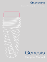
Procedural sizing chart
The diagram and chart below highlight some of the suggested procedures and recommended sizing.
11
10
9
7
65
4
3
2
1
7
77
8
12
13
14
15
Index Procedure Implant sizing
1Hallux IP Fusion 15x12
2MTPJ Fusion 18x15, 20x15, MTP
3Lapidus Fusion 15x15, 18x20, 18x25, 20x25 4 Leg
4Naviculocuneiform Fusion 18x15, 18x20, 20x15, 20x20
5Talonavicular Fusion 18x20, 18x25, 20x20, 20x25
6Calcaneocuboid Fusion 18x25, 20x20, 20x25, 4 Leg
7TMT Fusion 15x15, 15x20, 18x15, 18x20,
20x15, 20x20
8Chevron Osteotomy 15x15, 15x20,18x15, 18x20
9Metatarsal Osteotomy 15x15, 15x20, 18x15, 18x20,
20x15
10 Proximal Base Osteotomy 15x15, 15x20, 18x15, 20x15
11 Cotton Osteotomy 18x15, 18x20, 20x15, 20x20
12 Evans Osteotomy 20x20, 20x25, 25x20, 25x25
13 Calcaneal Osteotomy 20x20, 20x25, 25x20, 25x25
14 Subtalar Fusion 20x20, 20x25, 25x20, 25x25
15 Jones Fracture 15x12, 18x15

12
EasyFuse™ | Operative technique
Part number Description
FFS21512 EasyFuse Implant Procedure Pack, 15x12
FFS21515 EasyFuse Implant Procedure Pack, 15x15
FFS21520 EasyFuse Implant Procedure Pack, 15x20
FFS21815 EasyFuse Implant Procedure Pack, 18x15
FFS21820 EasyFuse Implant Procedure Pack, 18x20
FFS21825 EasyFuse Implant Procedure Pack, 18x25
FFS22015 EasyFuse Implant Procedure Pack, 20x15
FFS22020 EasyFuse Implant Procedure Pack, 20x20
FFS22025 EasyFuse Implant Procedure Pack, 20x25
FFS22520 EasyFuse Implant Procedure Pack, 25x20
FFS22525 EasyFuse Implant Procedure Pack, 25x25
FFSP1530 EasyFuse Instrument Procedure Pack
Ordering information
2-Leg Implant Part Numbers
Part number Description
FFS4MTPS EasyFuse Implant Procedure Pack, MTP, Small
FFS4MTPL EasyFuse Implant Procedure Pack, MTP, Large
FFS42520 EasyFuse Implant Procedure Pack, 4-Leg, 25x20
FFS43020 EasyFuse Implant Procedure Pack, 4-Leg, 30x20
FFSP1530 EasyFuse Instrument Procedure Pack
4-Leg Implant Part Numbers

13
EasyFuse™ | Operative technique
Notes

14
EasyFuse™ | Operative technique
Notes

15
EasyFuse™ | Operative technique
Notes

This document is intended solely for the use of healthcare professionals. A surgeon must always rely on his or her own
professional clinical judgment when deciding whether to use a particular product when treating a particular patient. Stryker
does not dispense medical advice and recommends that surgeons be trained in the use of any particular product before using
it in surgery.
The information presented is intended to demonstrate a Stryker product. A surgeon must always refer to the package insert,
product label and/or instructions for use, including the instructions for cleaning and sterilization (if applicable), before using
any Stryker product. Products may not be available in all markets because product availability is subject to the regulatory
and/or medical practices in individual markets. Please contact your Stryker representative if you have questions about the
availability of Stryker products in your area.
Stryker Corporation or its divisions or other corporate afliated entities own, use or have applied for the following
trademarks or service marks: EasyFuse, Stryker. All other trademarks are trademarks of their respective owners or holders.
AP-015450, 09-2021
Copyright © 2021 Stryker
Foot & Ankle
Manufacturer:
Stryker Corporation
1023 Cherry Road
Memphis, TN 38117
800 238 7117
901 867 9971
www.wright.com
/