Page is loading ...

SCORE
®
/ SCORE
®
AS
Primary Total Knee System
Mobile bearing
Surgical Technique
With Navigation
4-in-1 Instrumentation

Overview of SCORE
®
/ SCORE
®
AS TKS
•
The SCORE
®
TKS is a PCL-sacrificing, mobile bearing implant in rotation for primary knee
arthroplasty.
•
The stability is provided by sagittal and frontal congruency through the extension to the flexion.
•
The SCORE
®
TKS is available in cemented and cementless version.
•
The SCORE
®
AS TKS is coated with Titanium Nitride (TiN) to minimise allergic reactions
(cemented components only).

3
1. Femoral component:
Overview of SCORE
®
/ SCORE
®
AS TKS
Anterior cut at 6°
Component in Cobalt Chrome.
Dual coated cementless
component (80 μm plasma-
sprayed titanium + 80 μm
HAP). Cemented* component
is micro-blasted.
* SCORE
®
AS femoral component in Cobalt
Chrome, coated with 4 μm Titanium Nitride
(TiN). Cemented component only.
Thickness: 8 mm
Articulating surface with
mirror finish
Trochlear groove is offset
laterally by 6° allowing a
better stress distribution
Anatomic trochlea with a
single radius of curvature
Optimal shape of the
intercondylar box
ü For medio-lateral and
sagittal stabilisations with
regard to the insert: the
contact surface is increased
ü Reduced pressure on the
patella
Posterior cut at 2°
Radius of curvature
reducing over 100° in order
to increase flexion
Anterior edge respecting
the anatomy design
Notch on each side for
grasping
2 stabilisation pegs
Ø 8 mm x 13 mm
Not HAp coated in
cementless version
Trochlea closed in posterior
guaranteeing the largest
possible contact surface of
the condyle with the insert
Constant radius of curvature from
complete extension up to 100° flexion

4
The polyethylene patellar implant are available in three versions:
Overview of SCORE
®
TKS
2. Tibial component:
Rotative mobility of the tibial insert:
Thickness:
8 mm
UHMW PE
component
Congruency of the
femoral component
with tibial insert in
extension
Lateral
chamfers
Cylindrical and
conical plug
Central spinal massif
ü medio-lateral and
saggital stability
Large anterior chamfer
Thickness:
8,5 mm
Thickness:
7 mm
Resurfacing patella
with cement
Inserted patella
cemented
Inserted patella
cementless

5
Overview of SCORE
®
TKS
Tibial baseplate:
SCORE
®
/ SCORE
®
AS
Anatomical
coverage in
rotation
(mobile insert)
- Tibial extension stems:
- Ø 10 to 16 mm
- Length 75 to 200 mm
Possibility of using (e.g. in cases of uni revision, or TKA, or after osteotomy):
- Tibial half-wedges:
- Thickness 5 mm
- Thickness 10 mm
- Thickness 15 mm
- Offset connectors:
- 2 mm
- 4 mm
- 6 mm
Mirror polish finish
contact surface with
mobile insert
Component in Cobalt Chrome.
Dual coated cementless
component (80 μm plasma-
sprayed titanium + 80 μm
HAP). Cemented component
is micro-blasted.
3 sizes of delta wings
(sizes 1-2, 3-4-5, 6-7)
Conical tibial keel
shape identical for all
sizes
Tibial extension stems
available:
- Ø 10 to 16 mm
- Length 75 to 200 mm
Anatomical posterior shape
* SCORE
®
AS tibial component in Cobalt Chrome, coated with 4 μm Titanium Nitride (TiN). Cemented component only.

6
AP
AP
ML
ML
Overview of SCORE
®
TKS
3. SCORE
®
implant product range:
•
Femoral components:
- Cemented condyles: 7 sizes
- Uncemented condyles: 7 sizes
•
Patellar components:
- Resurfacing patella with cement: Ø 30, 33 and 36 mm
- Inserted patella cemented: Ø 23, 26 and 29 mm
- Inserted patella cementless: Ø 23, 26 and 29 mm
•
Tibial components:
- Cemented tibial baseplate: 7 sizes
- Uncemented tibial baseplate: 7 sizes
Δ AP: increment between sizes: 2.66 mm
Δ ML: increment between sizes: 3.3 mm
Increment between sizes: 2.3 mm
Increment between sizes: 3.5 mm
- Tibial inserts: 7 sizes
5 thickness (10, 12, 14, 16 and 20 mm)
Increment between sizes: 2.1 mm
Increment between sizes: 3.3 mm

7
4. Components compatibility:
Femoral component & insert size
Tibial baseplate size
S1
S1
S2
S2
S3
S3
S4
S4
S5
S5
S6
S6
S7
S7
Overview of SCORE
®
TKS
The SCORE
®
femoral implant is compatible with the whole range of patellar implants.

8
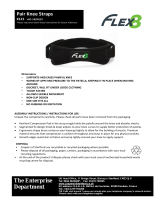
Workstation components
Camera head positioning
handles
Camera head positioning
handles
Carry handles (both sides)
Carry handles
(both sides)
Speakers
(both sides)
Laser control buttons
(bilateral)
LCD touch screen
22’’ LCD touch screen
USB ports
V2 Workstation
V3 Workstation
Front:
Laser pointer
Laser pointer
Optical sensors
Optical sensors
Status lights
Status lights
USB ports
Speakers
Power button

9
Workstation components
Camera head
release button
Power cord holder
Power
cord alimentation
Rear ports
Rear ports
On/Off switch
V2 Workstation
V3 Workstation
Rear:
Tower locking handles
Vent
Tower unlocking handle
Vent
Camera head
tightening knobs
Power cord holder

10
Latch
Latch
Front
Front
Pedals for V2 Workstation Pedals for V3 Workstation
Rear
Rear
Storage area
for pedal and
workstation cover
Storage area
for pedal and
workstation cover
Preparation phase
Shipping case for V2 Workstation
Shipping trunk for V3 Workstation

11
Preparation phase
•
Unlock the four latches on the shipping trunk.
•
Open the front panel and take out the workstation, pedal and pedal cover.
•
Place the workstation on a stable table or operating room cart.
•
Clean the workstation according to the instructions in the user manual or in the software.
NOTE: - The workstation user manual is found in the shipping trunk.
- It is also available under the ≪Options Menu≪ function in the software (see page 15).
•
Connect the pedal to the back of the V2 Workstation or to the side of the V3 Workstation (refer
to photos for location of ports) and slide it into its protective cover (found in the trunk).
•
Plug in the workstation’s power cord.

12
Preparation phase
Locked position
Unlocked position
Locking lever

13
Preparation phase
•
Position the workstation so that it is at least 1.5 m from the patient.
•
Set the camera head in neutral position (maximum height, no rotation).
•
Unlock the adjustable tower: lift the locking lever and let the tower rise freely until it reaches its
maximum height.
•
Press the power button:
- V2 Workstation: move the green button on rear of workstation
to « I » position;
- V3 Workstation: press the power button at lower right portion of screen
;
it will turn green when the power is on.

14
Screen layout
Title of current step
Information area and
buttons
Yellow pedal: indicates action
carried out when pedal is pressed
Blue pedal: action carried out when
pedal is pressed
Menu:
Options
Visibility of each array:
Green - visible
Red - not visible
Indicates if pointer
can be used as a mouse
on screen
Screenshot capture button
Active area

15
Options menu description
The «Exit Application»
button will only be
active during the final
step.
To exit the application
before the final step,
go to the «Options»
menu to select it.
Show camera field
of view to locate
arrays
Display gaps between
tibial cut and virtual
femoral component
Display gaps between
tibial cut and femoral
cut
Return to proximal
tibial cut navigation
step
Return to distal
femoral cut navigation
step
View all the validated steps
during the surgery
Reset navigation station position
relative to surgeon position
During the gap management step:

16

17
Preparation phase
•
Press the touch screen to select the preferred system language.
•
Select «Knee», then select the ANATOMIC
®
implant and the 4-in-1 protocol.
•
On the «Information» page, input the required information using the virtual keyboard.
- Surgeon name
- Patient name
- Patient date of birth (optional)
- Operated side (select right or left)
•
To go to the next step, press the blue pedal or the blue arrow on the screen.
•
To go to the previous step, press the yellow pedal or yellow arrow on the screen.
•
Configuring the surgery-related options:
- Order in which distal femoral and tibial cuts are performed
- Order in which trial implants are acquired

18
Marker
Spherical
Markers
Release button
Array
Fixation pins
Femur
Femur
array
Tibia array
Fixation pins
Array fixation
support

19
Preparation phase
•
Clip the round markers to the arrays:
- 3 for the Tibia (T) array
- 3 for the Femur (F) array
- 4 for the Pointer (P) array
- 3 for the Guide (G) array
•
The pins must be placed on the anteromedial side of the femur and tibia (when the surgeon
stands on the lateral side) and must not interfere with tap placement. They can be inserted
either percutaneously or through an incision.
NOTE: If the femoral pin is being inserted percutaneously, make sure the knee is flexed to prevent
damaging muscle fibres.
•
Insert the first pin: go through the proximal cortex and then into, but not through, the distal
cortex.
•
Place the array fixation support on the first pin to get the proper spacing for the second pin.
•
Clip the F array on the moveable part of the support, making sure the arrows are aligned
correctly. If the array needs to be removed during the procedure, it can be returned to the same
position on the support.
•
Orient the array towards the camera head and lock the fixation support.
•
Position and secure the arrays so they are always visible to the camera head, whether the knee
is flexed or extended.
Important: Once the knee joint has been opened and exposed with the retractors provided,
any osteophytes must be removed in order to acquire correct joint surfaces, otherwise the implant
selected may be too large or too small.

20
3D view
of arrays
/