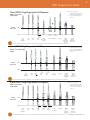
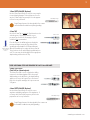
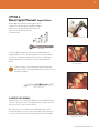
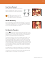
Keystone Dental Stage-1 is a single-stage implant system designed to simplify the implant procedure for both the patient and the clinician. It eliminates the second stage surgery, reducing trauma to the patient and chair time for both the patient and the surgeon. The Morse Taper Prosthetic Connection provides a mechanically locking friction fit between the implant and abutment, virtually eliminating loosening. The implant is suitable for use in partially or fully edentulous maxillae and mandibles, in support of single or multi-unit restorations.
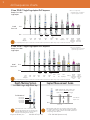
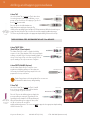
Keystone Dental Stage-1 is a single-stage implant system designed to simplify the implant procedure for both the patient and the clinician. It eliminates the second stage surgery, reducing trauma to the patient and chair time for both the patient and the surgeon. The Morse Taper Prosthetic Connection provides a mechanically locking friction fit between the implant and abutment, virtually eliminating loosening. The implant is suitable for use in partially or fully edentulous maxillae and mandibles, in support of single or multi-unit restorations.


-
 1
1
-
 2
2
-
 3
3
-
 4
4
-
 5
5
-
 6
6
-
 7
7
-
 8
8
-
 9
9
-
 10
10
-
 11
11
-
 12
12
-
 13
13
-
 14
14
-
 15
15
-
 16
16
-
 17
17
-
 18
18
-
 19
19
-
 20
20
-
 21
21
-
 22
22
-
 23
23
-
 24
24


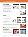
Keystone Dental Stage-1 is a single-stage implant system designed to simplify the implant procedure for both the patient and the clinician. It eliminates the second stage surgery, reducing trauma to the patient and chair time for both the patient and the surgeon. The Morse Taper Prosthetic Connection provides a mechanically locking friction fit between the implant and abutment, virtually eliminating loosening. The implant is suitable for use in partially or fully edentulous maxillae and mandibles, in support of single or multi-unit restorations.
Ask a question and I''ll find the answer in the document
Finding information in a document is now easier with AI
Related papers
-
 Keystone Dental Stage-1 Prosthetic Manual
-
 Keystone Dental RESTORE Surgical Manual
-
 Keystone Dental RESTORE Prosthetic Manual
-
 Keystone Dental Prima & Genesis Prosthetic Manual
-
 Keystone Dental TILOBEMAXX Surgical Manual
-
 Keystone Dental Prima Plus Surgical Manual
-
 Keystone Dental PrimaConnex Surgical Manual
-
 Keystone Dental I-HEXMRT Surgical Manual
-
 Keystone Dental TILOBEMAXX Surgical Manual
-
 Keystone Dental Genesis Surgical Manual


Other documents
-
 eazypower 88256 Installation guide
-
Midmark UltraClave M11 Specification
-
-
DENTSPLY 57H User manual
-
 Edge Systems HYDRAFACIAL Handpiece User manual
-
Zimmer enPulsPro User manual
-
-
 parkell D722 User manual
-
-
 Tuttnauer ELARA11-D Operation & Maintenance Manual


