Page is loading ...

Sports MedJoint Spine
Surgical Technique
CALIPERED KINEMATIC ALIGNMENT

GMK Sphere Calipered Kinematic Alignment Surgical Technique
2
INDEX
1. INTRODUCTION 4
1.1 Kinematic Alignment approach 4
1.2 Indications 4
1.3 Contraindications 5
1.4 Surgical Approach 5
2. TIBIO-FEMORAL OFFSET MEASUREMENT 5
3. DISTAL FEMORAL RESECTION 6
3.1 Placing the Intramedullary Rod 6
3.2 Positioning the Distal Cutting Guide 7
4. ANTERIOR CUT, POSTERIOR CUT AND CHAMFER 8
4.1 Femoral Sizing 8
4.2 4in1 Cutting Block Positioning 9
4.3 Posterior cut, anterior cut and chamfers 12
4.4 Femoral Upsizing/Downsizing 12
5. TIBIAL RESECTION 13
5.1 Mark the A/P axis on the tibia 13
5.2 Assembling the Extramedullary Guide 13
5.3 Setting the tibial varus/valgus with the extramedullary guide 14
5.4 Setting the tibial slope with the extramedullary guide 14
5.5 Setting the tibial resection level with the extramedullary guide 15
5.6 Stabilization of the tibial cutting block 15
5.7 Removing the extramedullary guide 15
5.8 Tibial resection 16
6. FLEXION GAP CHECK 16
7. EXTENSION GAP CHECK 17
8. TRIAL REDUCTION 18
8.1 Balance the TKA with trial components 19
8.2 Tibial bridge tray 21
9. FINISHING THE FEMUR AND TIBIA 22
9.1 Femoralnishing 22
9.2 Femoralnishingcheck 23
9.3 Tibial Finishing 24
9.4 Tibial stem extension 25

3
10. PATELL A 27
11. SELECTION OF THE PROSTHETIC COMPONENTS - SIZE MATCHING 28
12. FINAL IMPLANT 28
12.1 Tibial implant 28
12.2 Insert 29
12.3 Femoral implant 29
12.4 Patella 29
13. ANNEX 1 UNSLOTTED GUIDE COMPATIBILITY 30
13.1 Distal femoral resection 30
13.2 Proximal tibial resection 30
14. ANNEX 2 MIS GUIDE COMPATIBILITY 31
14.1 Distal femoral resection 31
14.2 Proximal tibial resection 32
15. ANNEX 3 4IN1 CUTTING BLOCK COMPATIBILITY 32
15.1 Posterior referencing: femoral sizing and external rotation adjustment 33
15.2 Posterior referencing: 4in1 cutting block positioning 33
15.3 Femoral upsizing/downsizing 34
16. IMPLANTS NOMENCLATURE 37
17. KA INSTRUMENT COMPLEMENT 40
18. COMPATIBILITY CHART 42

GMK Sphere Calipered Kinematic Alignment Surgical Technique
4
1. INTRODUCTION
1.1 KINEMATIC ALIGNMENT APPROACH
The three goals of Kinematically Aligned Total Knee
Arthroplasty are:
1. Restore the native tibial-femoral articular surfaces
2. Restore the native knee and limb alignments
3. Restore the native laxities of the knee.
This document describes the Calipered Kinematic
Alignment technique main steps to kinematically align the
femoral and tibial components to the native tibial-femoral
articular surface.
Through a series of caliper measurements, adjustments are
made until the thickness of the femoral and tibial resections
match the thickness of the femoral and tibial components
within ± 0.5 mm, after compensating for worn cartilage (~ 2
mm) and the kerf of the saw blade (~ 1 mm).
Hence, target caliper measurement = Implant Thickness -
Cartilage Wear - Saw Blade Thickness
This restores the native joint lines and co-aligns the axes of
the components with the three kinematic axes of the knee
without ligament release.
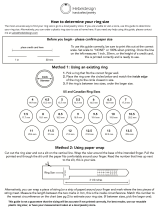
EXAMPLE: In a varus knee there is typically cartilage wear
on the medial distal condyle, whereas the lateral distal
condyle and the posterior condyles exhibit minimal wear.
Consequently:
Example target caliper measurements:
•
Unworn Posterior Femoral Condyles
= 8 mm - 0 mm - 1 mm = 7 mm
•
Worn Distal Femoral Condyles
= 9 mm - 2 mm -1 mm = 6 mm
•
Unworn Distal Femoral Condyle
= 9 mm - 0 mm - 1 mm = 8 mm
9 mm
1 mm
8 mm
1 mm
1.
The technique described in this document is applicable only
to cases where the anatomical landmarks required through
the procedure can be identified. If these landmarks are not
identifiable, alternative tools like patient matched technology
are required to kinematically align the femoral and/or tibial
components, provided enough information on the patient’s
native anatomy is available to plan implant positioning.
CAUTION
Should it not be possible to identify any of the anatomical
landmarks described in this surgical technique, follow the
steps described in the standard GMK Sphere surgical
technique (ref. 99.26SPHERE.12US & 99.26I.12US).
Complex cases should be carefully analyzed in order to
determine whether an alternative alignment approach or
additional corrections should be considered. For example,
extra-articular deformity might be best corrected with
realignment osteotomy.
1.2 INDICATIONS
The GMK Sphere is designed for cemented use in total
knee arthroplasty, if there is evidence of sufficient sound
bone to seat and support the components.
This knee replacement system is indicated in the following
cases:
•
Severely painful and/or disabled joint as a result of
arthritis, traumatic arthritis, rheumatoid arthritis or
polyarthritis.
•
Avascular necrosis of femoral condyle.
•
Post traumatic loss of joint configuration.
•
Primary implantation failure.
GMK Sphere can be implanted using a kinematic alignment
approach. When a kinematic alignment approach is utilized,
this knee replacement system is indicated in the following
cases:
•
Severely painful and/or disabled joint as a result of
arthritis, traumatic arthritis, rheumatoid arthritis or
polyarthritis.
•
Collagen disorders, and/or avascular necrosis of the
femoral condyle.
•
Moderate valgus, varus, or flexion deformities.
Tibial wedges cemented are to be attached to the tibial
baseplate with both the fixing cylinders and bone cement.
The screwed tibial augments are for screwed fixation to the
tibial baseplate.

5
1.3 CONTRAINDICATIONS
Total knee replacement is contraindicated in the following
cases:
•
Progressive local or systemic infection.
•
Muscular loss, neuromuscular disease or vascular
deficiency of the affected limb, making the operation
unjustifiable
•
Severe instability secondary to advanced destruction
of condylar structures or loss of integrity of the lateral
ligament.
Mental or neuromuscular disorders may create an
unacceptable risk to the patient and can be a source of
postoperative complications. It is the surgeon’s
responsibility to ensure that the patient has no known
allergy to the materials used.
The Kinematic Alignment Surgical Technique is
contraindicated also for patients with greater than 5°
valgus deformity with MCL insufficiency.
1.4 SURGICAL APPROACH
The most common surgical approach is the vertical midline
skin incision and a medial parapatellar approach. Other
approaches may be used depending on the surgeon’s
preferences. After exposing the joint via elevation of the
medial retinaculum, flex the knee. Prior to any bone
resection define the normal bony architecture by removing
the osteophytes (including those at the intercondylar
notch) as collectively these contribute to the maintenance
of any malalignment and conceal the true bone size.
Resect the anterior cruciate ligament. If you are using a
GMK Sphere CS insert, resect also the posterior cruciate
ligament which also aids exposure by permitting easier
subluxation of the tibia for its subsequent osteotomy.
CAUTION
If a cruciate retaining insert (CR Insert) is used, the posterior
cruciate ligament must be preserved.
During all procedures it is the intention to replace the bone
and cartilage, that has been lost secondary to the arthritic
process and resected as part of the arthroplasty, with a
similar thickness of polyethylene and metal provided by the
prosthetic components.
2. TIBIO-FEMORAL OFFSET MEASUREMENT
When using a GMK Sphere CR insert, the measurement of
the tibio-femoral offset can be a reference to check the
slope once the trial implants are in place. Flex the knee to
90°. Expose the knee using a medial approach. Position the
arms of the offset caliper against the distal medial femoral
condyle and anterior tibia. Orientate the longer arm parallel
to the patella tendon. Measure the distance. When cartilage
on the medial femoral condyle is worn to the bone subtract
2 mm from the offset measurement.
2.
3.
CAUTION
This measurement is not reliable in case of deficient ACL
with postero-medial wear of the tibia.
To evaluate the slope in such cases please refer to the table
GMK Sphere decision tree - CR insert in chapter 8.1.

GMK Sphere Calipered Kinematic Alignment Surgical Technique
6
3. DISTAL FEMORAL RESECTION
Calipered kinematic alignment sets the femoral component
coincident to the distal articular surface of the native femur.
Restoring the native distal femoral line requires
compensations of ~2 mm for worn cartilage when present
on the distal femoral condyles. When measuring the cut,
~1 mm of saw blade kerf should be accounted for.
Compensation for bone wear is rarely required at the 0°
of flexion position on the osteoarthritic femoral condyle
with end-stage varus or valgus deformity.
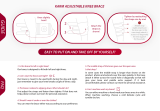
3.1 PLACING THE INTRAMEDULLARY ROD
First, set the flexion-extension position of the femoral
component. Drill a hole midway between the top of the
intercondylar notch and the anterior cortex, depending on
the anterior-posterior size of the femur. Keep a 5-10 mm
bridge of bone between the posterior rim of the drill hole
and the top of the intercondylar notch. Orient the drill
parallel to the anterior surface and perpendicular to the
distal articular surface of the distal femur.
CAUTION
Excessive flexion of the femoral component could lead to
patellar instability. Orienting the drill hole parallel to the
anterior surface of the distal femoral shaft minimizes
flexion of the femoral component.
90°
5-10 mm
4.
Insert the rod 8-10 cm into the femur using the marks
engraved on the shaft as a reference.
5.
Determine the extent of cartilage wear on each distal
femoral condyle. Use a ring curette to remove any partially
worn cartilage on the bone.
Set the varus-valgus angle and proximal-distal level of the
femoral component. This is done using a distal cut
referencing guide. The guide can compensate for 2 mm of
cartilage wear on the worn condyle(s).
4 distal referencing guides are available:
•
1x UNWORN/UNWORN: This is for cases with no
cartilage wear on either distal femoral condyle
•
1x UNWORN/WORN: This is for cases with cartilage
wear on the right medial or left lateral condyle
•
1x WORN/UNWORN: This is for cases with cartilage
wear on the left medial or right lateral condyle
•
1x WORN/WORN: This is for cases with wear on both
distal femoral condyles
6.
Select the appropriate guide depending on the operative
side and the pattern of cartilage wear.
Place it onto the intramedullary rod and advance it until it
contacts both femoral condyles. Stabilize the distal cut
reference guide by means of two threaded pins into the
distal holes.

7
3.2 POSITIONING THE DISTAL CUTTING GUIDE
Slide the fixed slotted distal cut positioner onto the distal
cut reference guide.
Connect the distal cutting block to the fixed slotted distal
cut positioner then secure the connection by pushing the
lever down.
CAUTION
The slotted distal cutting guide is NOT compatible with the
Micrometric Distal Cut Positioner unslotted version
(ref.02.07.10.0185).
7.
The femoral distal resection is set at 9 mm, corresponding
to the thickness of the distal condyles of the femoral
component.
OPTION
Alternatively, a micrometric distal cut positioner is available.
The distal resection level can be adjusted by turning the
screw on the distal cut positioner. Make sure to set a 9 mm
distal resection.
Stabilize the distal cutting block by inserting two pins in the
parallel positioning holes (marked in red in the figure below)
and one pin in the oblique hole (marked in blue in the figure
below) and then remove everything except the distal cutting
block by releasing the lever.
Reference Line
Standard distal slotted cutting block
8.
Distal cutting block holes (right knee)
Parallel positioning holes
Oblique fixation holes
Alignment rod holes
Parallel repositioning holes
Additional fixation holes
9.
Check the distal femoral resection level using the angel
wing. Perform the distal cut with a 1.27 mm thickness saw
blade through the slot built into the guide. Once the
resection is performed, remove the pins.
VERIFICATION CHECK
Using the dedicated caliper, check the thickness of the
resected medial and lateral distal femoral bone and
cartilage (if present) resection. Measurement on the
unworn condyles should read 8.0 ± 0.5 mm. Worn condyles
should measure 6.0 ± 0.5 mm. These values equal the 9
mm thickness of the distal condyles of the GMK Sphere
femoral component after compensating for the ~1 mm
kerf of the saw blade and 2 mm of worn cartilage when
present.

GMK Sphere Calipered Kinematic Alignment Surgical Technique
8
In cases of a 1 mm under-resection, refine the cut through
the slot of the distal cutting block.
Should a recut be necessary, use the repositioning holes to
move the distal cutting block proximally in 2 mm
increments. Before performing the recut, check the distal
cutting block position with an angel wing.
If one or both condyles have been over-resected by 1 or 2
mm, the correct joint line level is restored using dedicated
washers, as described in the next section.
TIP
Mark the number of millimeters of over-resection on each
distal femoral condyle with a pen as a reference for
selecting the correct washer.
4. ANTERIOR CUT, POSTERIOR CUT AND CHAMFER
Calipered kinematic alignment sets the femoral component
coincident to the posterior articular surface of the native
femur. Restoring the native posterior femoral line requires
compensation for cartilage wear when present.
Compensation for bone wear at 90° of flexion position is
rarely required on the osteoarthritic femoral condyle with
end-stage varus or valgus deformity.
Set the anterior-posterior translation and internal-external
rotation of the femoral component by placing the 0°
posterior referencing guide in contact with the posterior
femoral condyles.
Use the 4in1 cutting block to perform the anterior, posterior,
and chamfer resections of the femur. All femoral resections
must be performed using a sawblade 13 mm wide with a
maximum thickness of 1.27 mm.
10.
4in1 cutting block holes
Parallel positioning holes (Posterior Referencing)
Parallel positioning holes (Anterior Referencing)
Handle holes
Oblique fixation holes
Cancellous bone screw holes
4.1 FEMORAL SIZING
A modular femoral sizer is available to position the 4in1
cutting block.
Select the 0° rotational guide. Slide the rotational guide
onto the driven pins to connect the rotational guide to the
posterior referencing femoral sizer. A ‘click’ will be heard
when it is fully engaged.
11.
The posterior referencing femoral sizer must be flush
against the cut edge of the distal femur. Both the posterior
condyles should be in contact to its base. The position of
the posterior referencing guide rarely requires correction
because it is uncommon for the posterior femoral condyles
to experience complete cartilage loss.
TIP
Insert an angel wing between the foot of the Posterior
Referencing Femoral Sizer posterior to the worn femoral
condyle when compensating for worn cartilage.

9
12.
To measure the size of the femur:
1. The stylus should contact the anterior ridge of the lateral
femoral cortex.
2. The posterior plates should be in contact with both the
medial and lateral posterior femoral condyles.
The size can be read on the front of femoral sizer.
13.
The position of the sizer can be refined by selecting the size
of the femur using the anterior stylus.
14.
4.2 4IN1 CUTTING BLOCK POSITIONING
Option 1: Posterior Pegs
Once the size has been established, drill through the
dedicated peg holes, indicated in blue on the picture below,
on the femoral sizer to prepare for the posterior pegs on the
4in1 block.
15.
Femoral sizer holes
Parallel positioning holes (Posterior Referencing)
4in1 peg drilling holes (Posterior Referencing)
Epicondylar axis reference holes
Fixation holes
CAUTION
While drilling, ensure that contact between the femoral
sizer and the distal resection remains flush and intact.

GMK Sphere Calipered Kinematic Alignment Surgical Technique
10
OPTION
To achieve further stabilization, insert two pins into the
fixation holes.
Remove the femoral sizer from the bone. Select the 4in1
block which corresponds to the size previously determined.
Prepare the 4in1 cut block by assembling the pegs to the
back of the cutting block. Apply the 4in1 block onto the
distal femoral resection.
Check the level of the anterior cut by placing the angel wing
into the slot of the anterior resection.
16.
CAUTION
The position of the 4in1 cutting block pegs DOES NOT
CORRESPOND to the position of the final femoral
component lugs. Preparation for the lugs of the final
femoral component is in a later step.
If one or both distal condyles were over-resected, move the
position of the 4in1 block distally using the dedicated 1 and
2 mm washers.
17.
To apply the washer, slide it over the posterior peg of the
4in1 block until it contacts the flat surface of the back of
the 4in1 block. Secure the washer by inserting the short
fixation peg on the washer into the cancellous bone screw
hole. Confirm the washer lies flush.
18.
NOTE: The position of the cancellous bone screw holes
relative to the posterior fixation pegs changes from size to
size.
Secure the 4in1 block by inserting two headed pins into the
lateral oblique fixation holes.
Option 2: Posterior Referencing Pins
CAUTION
If a correction washer is required, the posterior referencing
pins cannot be used.
Once the size has been established, pre-drill the medial and
lateral posterior referencing pin holes through the femoral
sizer. Then insert one pin in the medial hole and one pin in
the lateral hole.
CAUTION
While drilling, ensure that contact between the femoral
sizer and the distal resection is maintained.
Remove the femoral sizer by sliding it off the medial and
lateral pins inserted.

11
19.
Select the 4in1 block which corresponds to the size
previously determined. Slide the 4in1 block over the pins
through the corresponding row of parallel positioning holes
until it contacts the distal resection.
Check the level of the anterior cut by placing the angel wing
into the slot of the anterior resection.
Once the position of the 4in1 block is satisfactory, secure
the cutting block by inserting two headed pins into the two
lateral oblique fixation holes. Remove the positioning pins.
OPTION
If no correction washers were used, cancellous bone
screws can be used alternatively or together with the lateral
pins to stabilize the 4in1 guide. Insert the cancellous bone
screws through the dedicated holes using the dedicated
screwdriver.
20.
CAUTION
It is strongly recommended not to impact or hammer the
4in1 guide with a mallet. If the surgeon considers such
action necessary, do not impact directly on the 4in1 guide.
Use the femoral impactor as shown in the picture below.
21.

GMK Sphere Calipered Kinematic Alignment Surgical Technique
12
4.3 POSTERIOR CUT, ANTERIOR CUT AND
CHAMFERS
When the 4in1 cutting block has been stabilized via either
the posterior referencing pegs or posterior referencing pins,
perform the posterior condylar cut.
VERIFICATION CHECK
Using the dedicated caliper, check the thickness of the
resected medial and lateral posterior femoral bone and
cartilage (if present) resections. Measurement on the
unworn condyles should read 7.0 ± 0.5 mm. Worn condyles
should measure 5.0 ± 0.5 mm. These values equal the 8
mm thickness of the posterior condyles of the GMK Sphere
femoral component after compensating for the ~1 mm
kerf of the saw blade and 2 mm of cartilage wear when
present.
If needed, refine the cut through the slot of the 4in1 block.
In the rare event a 2 mm recut is necessary, reposition the
block using the posterior referencing pins.
If the posterior referencing pegs were used, position the
two central pins on the row of holes marked with a line.
Remove the cutting block, withdraw the two pegs and
reposition the pin holes just below the reference line.
If a 1 or 2 mm washer was used, place an angel wing
between the 4in1 block and the bone on the over-resected
condyle.
Perform the remaining femoral resections as follows:
•
Anterior cut
•
Posterior chamfer
•
Anterior chamfer
CAUTION
All femoral resections must be performed using a saw
blade 13 mm wide with a maximum thickness of 1.27 mm.
Remove the fixation pins, pegs and/or screws and then
remove the 4in1 block.
4.4 FEMORAL UPSIZING/DOWNSIZING
The difference between successive femoral sizes is 2 mm
in both anterior-posterior and medio-lateral dimensions.
Option 1: Posterior Pegs
Replace the 4in1 block with a more suitable size using the
posterior peg holes.
CAUTION
In the event downsizing is necessary, the anterior resection
level will move 2 mm posteriorly. Use an angel wing to
check this adjustment and ensure the downsized 4in1
block cuts will not result in anterior notching of the femur.
Option 2: Posterior Referencing Pins
If the 4in1 cutting block was positioned using the central
parallel pins, replace the cutting guide with the more
suitable size using the same row of pin holes.
CAUTION
In the event downsizing is necessary, the anterior resection
level will move 2 mm posteriorly. Use an angel wing to
check this adjustment and ensure the downsized 4in1
block anterior cut will not result in anterior notching of the
femur.

13
5. TIBIAL RESECTION
Calipered kinematic alignment sets the tibial component
parallel to the flexion-extension axis of the native knee and
coincident with the plane of the native tibia, which means
restoring the varus-valgus and the slope, after compensating
for cartilage and bone wear.
5.1 MARK THE A/P AXIS ON THE TIBIA
On the lateral tibial condyle, mark the anterior-posterior axis
(blue line) of the almost elliptically-shaped boundary of the
articular surface (black dots).
Mark also the anterior-posterior axis that passes through
the center of the tibia and parallel to the A/P axis of the
lateral compartment.
This will be the reference to adjust the rotation of the tibial
cutting block.
22.
5.2 ASSEMBLING THE EXTRAMEDULLARY GUIDE
The extramedullary guide consists of the following
components:
F
E
D
C
B
A
23.
Malleolar clamp (A)
Malleolar clamp support (B)
Tibial resection guide distal part (C)
Eyeballing extramedullary superior guide (D)
Tibial slotted cutting guide (E)
Tibial stylus (F)

GMK Sphere Calipered Kinematic Alignment Surgical Technique
14
Select the tibial slotted cutting guide which corresponds to
the operative side (left or right). Fix the slotted tibial cutting
guide to the extramedullary eyeballing superior guide using
the set screw provided (black circle). Insert the malleolar
clamp (A) into the malleolar clamp support (B). Slide the
distal part of the tibial resection guide (C) into the malleolar
clamp support. Then slide the eyeballing extramedullary
superior guide (D) into the distal part of the tibial resection
guide.
Secure the malleolar clamp around the ankle.
Position the assembly on the tibia and adjust the frontal
rotation. The mark engraved on the top of the tibial slotted
cutting guide should be aligned to anterior-posterior axis of
the lateral tibial condyle previously marked.
24.
Adjust the distance of the rods to the length of the patient’s
tibia and fix with the knob provided (grey arrow). A stylus
(F) is provided to check the tibial resection level.
OPTION
Once the tibial slotted cutting block is positioned on the
tibia, insert a pin into the central slot to fix the rotation.
Inserting this pin will still allow adjustment of the tibial
slope and varus/valgus.
Central Slot
25.
CAUTION
The cutting block does not have a built-in slope, i.e. when
the extramedullary jigs are aligned with the tibial axis, the
system provides a slope of 0°.
5.3 SETTING THE TIBIAL VARUS/VALGUS WITH
THE EXTRAMEDULLARY GUIDE
TIP
Set the varus-valgus orientation of the tibial resection
parallel to the articular surface of the native tibia
compensating for cartilage and bone wear. Translating the
malleolar clamp support 15 mm lateral sets the guide to
~ 3° varus to the tibial mechanical axis. Visually fine-tune
the varus/valgus setting of the tibial cutting guide looking
at the tibia articular surface.
26.
5.4 SETTING THE TIBIAL SLOPE WITH THE
EXTRAMEDULLARY GUIDE
Place an angel wing in the saw slot of the slotted tibial
cutting guide. Set the tibial slope by sliding the distal part
of the malleolar clamp support along the malleolar clamp
rod until the angel wing is parallel to the slope of the medial
joint line after compensating for cartilage and bone wear.
27.
It is recommended to avoid any excessive posterior slope,
and it is important to check that no anterior slope is
introduced.

15
5.5 SETTING THE TIBIAL RESECTION LEVEL WITH
THE EXTRAMEDULLARY GUIDE
Fix the tibial stylus into the dedicated hole on the cutting
guide. One side of the stylus allows to make a 8 mm cut
from the less worn tibia plateau, and the other side to make
a 2 mm from the most worn plateau.
Set the proximal-distal translation of the tibial component
by adjusting the level of the saw slot until the 8 mm side of
the tibial stylus contacts the center of the less worn tibial
condyle.
28.
The goal is to perform a conservative resection that allows
for any corrections or recuts that might be necessary to
re-establish soft tissue balance.
5.6 STABILIZATION OF THE TIBIAL CUTTING
BLOCK
Check the cut height and posterior slope using the angel
wing before fixing the tibial cutting block.
Pin the block to the tibia by using the two parallel positioning
holes marked with a line and one oblique fixation hole.
Tibial slotted cutting block - right side
Reference line
29.
Parallel positioning holes
Oblique fixation holes
Tibial stylus holes
Sawblade slot
5.7 REMOVING THE EXTRAMEDULLARY GUIDE
Remove the stylus by pulling it upwards (1). Unlock the
frontal screw of the extramedullary guide body (2). Open
the malleolar clamp (3) and remove the construct from the
patient (4).
1
2
4
3
30.

GMK Sphere Calipered Kinematic Alignment Surgical Technique
16
5.8 TIBIAL RESECTION
Bring the tibial cutting guide into contact with the tibia by
sliding it along the pins. If an increase in stability is required,
a third oblique pin can be introduced through the oblique
hole of the tibial slotted cutting block.
31.
CAUTION
Check that the rotation and varus/valgus of the tibial
cutting guide has not changed during disassembly of the
guides before performing the resection.
Finally, perform the tibial proximal resection by cutting with
a 1.27 mm thickness saw blade through the slot built into
the guide. Slide the tibial cutting block over its two parallel
pins and remove it.
VERIFICATION CHECK
Measure the thickness of the resected medial and lateral
tibial condyles at the base of the tibial spines. This two
measurements should be equal ± 0.5 mm. When one tibial
condyle is thinner than the other by 1 mm or more, expect
tightness in that compartment and/or slackness in the
other when assessing varus-valgus laxity with the knee in
full extension. Confirm the slope of the medial tibial
resection is parallel to the native slope after compensating
for wear. Any adjustment is performed only after checking
the flexion/extension gap, as described in the following
sections.
32.
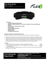
6. FLEXION GAP CHECK
Test the flexion gap using the flexion-extension spacers
(available thicknesses: 10, 11, 12, 13, 14 mm). Use the side
marked as “FLEX”.
At 90° of flexion lateral laxity should be higher than medial
laxity, which matches the native laxities of the knee.
33.
VERIFICATION CHECK
Assess the relative tightness between the medial and
lateral compartments by internally and externally rotating
the spacer. The spacer should fit tight and pivot about the
medial compartment and fit loose in the lateral
compartment. This tighter medial/looser lateral fit indicates
a trapezoid shaped flexion space like the native knee.

17
7. EXTENSION GAP CHECK
Test the extension gap with the flexion-extension spacer
(available thicknesses: 10, 11, 12, 13, 14 mm). Use the side
marked as “EXT”.
34.
Retract the medial and lateral soft-tissues and view the
interfaces between the femoral resection, spacer, and tibial
resection. Manually apply a varus-valgus stress with the
knee in full extension.
Confirm that laxity is negligible.
OPTION
As an alternative, modular spacers can be used in order to
check the extension gap. The femoral spacer simulates the
thickness of the femoral component, while the independent
cut reference spacer simulates the thickness of the tibial
component plus the minimum 10 mm insert. Assemble the
independent cut reference spacer with the femoral spacer
and the removable handle and introduce it into the joint
space.
35.
In case of laxity, the thickness of the different PE inserts
(11, 12, 13, 14, 17 and 20 mm) can be simulated by using
different tibial spacers (11, 12, 13, 14, 17 and 20 mm).
The femoral spacer must be fixed to the reference spacer
on the side marked “FEMORAL”. Similarly, the tibial spacer
must be fixed to the reference spacer on the side marked
“TIBIAL”.
19 mm
Trial femur
Femoral spacer
Independent cut
reference spacer
Trial tibia 10 mm tibial insert
Final implant
36.

GMK Sphere Calipered Kinematic Alignment Surgical Technique
18
VERIFICATION CHECK
At 0°of flexion varus/valgus laxity should be minimized and
native knee and limb alignments should be restored. The
medial and lateral gaps should be equally stable when
applying the varus-valgus stress, which restores both a
tight rectangular extension gap and the compartment
forces like the native knee.
CAUTION
If 1 or 2 mm washers were used in combination with the
4in1 block, an equivalent laxity should be allowed when
evaluating the thickness of the tibial insert.
If necessary, a 2 mm recut can be performed through the
dedicated block. Position the block on the cut surface and
stabilize it inserting two pins in the fixation holes before
cutting.
37.
If a correction is needed to restore a tight rectangular gap,
follow the steps below.
TIGHT MEDIAL & LOOSE
LATERAL IN EXTENSION
TIGHT LATERAL & LOOSE
IN MEDIAL EXTENSION
Remove medial osteophytes.
Reassess.
Recut tibia in 1°- 2° more
varus.
Insert 1 mm thicker spacer.
Remove lateral osteophytes.
Reassess.
Recut tibia in 1° - 2°more
valgus.
Insert 1mm thicker spacer.
Varus and valgus adjustments of 2° can be performed
through the dedicated blocks. Position the appropriate
block on the cut surface and stabilize it inserting two pins
in the fixation holes before cutting.
38.
8. TRIAL REDUCTION
To position the tibial trial, attach the tibial trial insert of the
correct thickness on the appropriately sized tibial trial.
Connect the removable handle and place the tibial trial on
the tibial cut plane. The tibial baseplate is asymmetrical.
Rotate the baseplate until the best coverage of the tibial
cortical bone is achieved.
39.

19
Assemble the femoral impactor/extractor on the slide
hammer and impact the appropriate size trial femur
centering it on the anatomical notch. Ensure medial or
lateral overhang is minimized.
40.
To change the thickness of the tibial trial insert, pull the
lever (A) and substitute with a more appropriate trial insert.
Remove the handle by pressing the button (B) and reduce
the patella. Test the knee by moving it through its full range
of motion to ensure optimal tracking of the components.
B
A
41.
CAUTION
During trialing, remove the trial femur before changing the
trial insert. Changing the trial insert with the trial femur in
place could be difficult due to the conformity of the medial
compartment.
8.1 BALANCE THE TKA WITH TRIAL COMPONENTS
If corrections are needed, a stepwise alignment algorithm
determines the actions to achieve kinematic alignment.
The underlying principle of this algorithm is that the
corrections requiring a recut of bone are performed by fine-
tuning the varus/valgus, slope, and proximal-distal
positions of the tibial resection, and not by recutting the
femur.
Balance the knee in full extension, 15-20° of flexion, and 90°
of flexion referring to the steps in the GMK Sphere CS and
Sphere CR Decision-Trees below.
Balance the TKA in Full Extension and 15-20° of Flexion
Place the knee in full extension. Confirm the knee fully
extends without a flexion contracture.
Retract the medial and lateral soft-tissues and examin the
interface between the femoral component and insert. Manually
apply a varus-valgus stress. Confirm the laxity is negligible and
increase insert thickness if needed.
Flex the knee 15-20°. Confirm the lateral compartment opens
~2 mm more than the medial compartment.
Balance the TKA in 90° of Flexion
Place the knee in 90° of flexion. Manually distract the tibia
from the femur, apply a posterior drawer test. Confirm the
knee is stable. If corrections are needed, refer to the steps
in the GMK Sphere - Flex Insert and GMK Sphere - CR Insert
decision trees below.
CAUTION
When using GMK Sphere Flex insert, confirm complete
resection of the posterior cruciate ligament.
VERIFICATION CHECK
When using the GMK Sphere CR insert, confirm the A-P
offset matches the offset measured at the time of exposure.
When the A-P offset is greater than at exposure and the
knee is tight in flexion and well-balanced in extension,
recheck the tibial slope and insert thickness. Refer to the
steps in point 4 in the GMK Sphere - CR Insert decision
trees below.
When the A-P offset is less than at exposure and the knee
is well-balanced in extension and loose in flexion, recheck
the integrity of the posterior cruciate ligament, the tibial
slope, and the insert thickness. Refer to the steps in point
6 in the GMK Sphere - CR Insert decision trees below.
It is possible to adjust the posterior slope (+/- 2°) using the
dedicated recut block. Ensure that the correction cutting
blocks are positioned on the same row of holes used to
perform the initial tibial resection.
42.
After any correction is applied, check again the extension
and flexion gaps.

GMK Sphere Calipered Kinematic Alignment Surgical Technique
20
FLEXION
EXTENSION
Tight Ok Loose
Tight 1 2 3
OK 4 5 6
GMK SPHERE DECISION-TREE - FLEX INSERT
1. If the joint is tight both in extension and flexion recut
tibia and remove 1-2 mm more bone (or if possible
decrease the thickness of the articular surface)
2. If the joint is tight in extension and well balanced in
flexion:
•
Remove posterior femoral osteophytes.
•
Strip posterior capsule.
•
Insert trial component and gently manipulate knee
into extension.
•
Reassess.
•
Resect additional proximal tibial bone with decreased
posterior slope and increase the thickness of the
articular surface.
3. If the joint is tight in extension and loose in flexion:
•
Remove posterior osteophytes.
•
Strip posterior capsule.
•
Insert trial component and gently manipulate knee
into extension.
•
Reassess.
•
Resect an additional 2 mm from the distal femur and
use a 2-mm thicker liner. *
4. If the joint is well balanced in extension and tight in
flexion:
•
Confirm complete resection of the PCL.
•
Increase posterior slope.
5. If the joint is well balanced both in extension and flexion
no further modifications are necessary.
6. If the articulation is well balanced in extension and loose
in flexion:
•
If still loose in flexion reduce slope or resect 1 - 2
mm bone from distal femur and add thicker Sphere
CS insert.
•
Add thicker spacer and recheck knee extends fully.
•
Remove posterior osteophytes.
•
Strip posterior capsule.
•
Insert trial component and gently manipulate knee
into extension.
•
Reassess.
•
Resect additional proximal tibial bone with
decreased posterior slope and increase the
thickness of the articular surface.
* This approach requires the surgeon to accept
that raising the femoral joint line by 2 mm
violates the kinematic alignment goal of restoring
the native tibial-femoral articular surfaces
FLEXION
EXTENSION
Tight Ok Loose
Tight 1 2 3
OK 4 5 6
GMK SPHERE DECISION-TREE - CR INSERT
1. If the joint is tight both in extension and flexion recut
tibia and remove 1-2 mm more bone (or if possible
decrease the thickness of the articular surface)
2. If the joint is tight in extension and well balanced in
flexion:
•
Remove posterior osteophytes.
•
Strip posterior capsule.
•
Insert trial component and gently manipulate knee
into extension.
•
Reassess.
•
Resect additional proximal tibial bone with decreased
posterior slope and increase the thickness of the
articular surface.
3. If the joint is tight in extension and loose in flexion:
•
Remove posterior osteophytes.
•
Strip posterior capsule.
•
Insert trial component and gently manipulate knee
into extension.
•
Reassess.
•
Resect an additional 2 mm from the distal femur and
use a 2-mm thicker liner. *
4. If the joint is well balanced in extension and tight in
flexion, increase posterior slope until native A-P offset is
restored at 90° of flexion.
5. If the joint is well balanced both in extension and flexion
no further modifications are necessary.
6. If the articulation is well balanced in extension and loose
in flexion:
•
When knee does not fully extend check PCL tension.
•
When PCL is incompetent use Sphere Flex insert.
•
Add thicker spacer and recheck knee extends fully.
•
Remove posterior osteophytes.
•
Strip posterior capsule.
•
Insert trial component and gently manipulate knee
into extension.
•
Reassess
•
Resect additional proximal tibial bone with
decreased posterior slope and increase the
thickness of the articular surface.
* This approach requires the surgeon to accept
that raising the femoral joint line by 2 mm violates
the kinematic alignment goal of restoring the native
tibial-femoral articular surfaces
/