Page is loading ...

Trademark Acknowledgements
Prima, PrimaConnex, PrimaSolo, RENOVA, RESTORE, STAGE-1, DynaBlast, DynaGraft•D, DynaMatrix, CALMATRIX,CALFORMA,TEFGEN-FD, TEFGEN-PLUS,TEFGEN and
TiLobe are trademarks of Keystone Dental, Inc.
The products described herein are covered by one or more of the following patents:
US 5,99 6 ,7 7 9 , US 6,142,296, US 7,249,949, and applicable international patents.
Additional patents are pending.
© Keystone Dental, Inc. 20 0 9 MK40040 Rev. A
Manufacturer
Keystone Dental, Inc.
144 Middlesex Turnpike
Burlington, MA 01803 USA
Call: 1-866-902-9272
Fax: 1-866-903-9272
Outside the USA
Call: +1-781-328-3490
Fax: +1-781-328-3400
Authorized Representative
Keystone Dental SpA
via A. Fleming, 19
37135 Verona, Italy
Call: +39-045-8230294
Fax: +39-045-8250296
Subsidiary:
Keystone Dental AB
Särö, Sweden
Call: +46-31-93-68-23
Fax: +46-31-93-68-45
Subsidiary:
Keystone Dental GmbH
Alfter, Germany
Call: +49-2222-9294-0
Fax: +49-2222-977356
Subsidiary:
Keystone Dental S.A.S.
Beauzelle, France
Call: +33-5-62-21-40-45
Fax: +33-5-61-42-06-32
Email: [email protected]
www.keystonedental.com
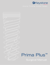
RESTORE
®
Implant System
Surgical Manual
0123
only
Trademark Acknowledgements
Prima, PrimaConnex, PrimaSolo, RENOVA, RESTORE, STAGE-1, DynaBlast, DynaGraft•D, DynaMatrix, CALMATRIX,CALFORMA,TEFGEN-FD, TEFGEN-PLUS,TEFGEN and
TiLobe are trademarks of Keystone Dental, Inc.
The products described herein are covered by one or more of the following patents:
US 5,99 6 ,7 7 9 , US 6,142,296, US 7,249,949, and applicable international patents.
Additional patents are pending.
© Keystone Dental, Inc. 20 0 9 MK40040 Rev. A
Manufacturer
Keystone Dental, Inc.
144 Middlesex Turnpike
Burlington, MA 01803 USA
Call: 1-866-902-9272
Fax: 1-866-903-9272
Outside the USA
Call: +1-781-328-3490
Fax: +1-781-328-3400
Authorized Representative
Keystone Dental SpA
via A. Fleming, 19
37135 Verona, Italy
Call: +39-045-8230294
Fax: +39-045-8250296
Subsidiary:
Keystone Dental AB
Särö, Sweden
Call: +46-31-93-68-23
Fax: +46-31-93-68-45
Subsidiary:
Keystone Dental GmbH
Alfter, Germany
Call: +49-2222-9294-0
Fax: +49-2222-977356
Subsidiary:
Keystone Dental S.A.S.
Beauzelle, France
Call: +33-5-62-21-40-45
Fax: +33-5-61-42-06-32
Email: [email protected]
www.keystonedental.com
RESTORE
®
Implant System
Surgical Manual
0123
only

2
Keystone Dental, Inc. 866-902-9272 (U.S.A.) 1-781-328-3490 (International) www.keystonedental.com
pre-surgical considerations
Symbols Key
= Note = Tip
Introduction
The RESTORE Surgical Manual is designed to aid clinicians in surgical procedures using Keystone Dental’s RESTORE
External Hex Implant System. Keystone Dental’s RESTORE External Hex Implant System is built upon a history of clinically
proven designs combined with enhancements that improve fit, function and overall ease-of-use. The External Hex
Prosthetic Connection is backed by almost 40 years of successful clinical experience. Restoratively, the RESTORE System
provides straightforward options for cement-retained, screw-retained and overdenture restorations. The procedures and
guidelines presented in this Manual are not a substitute for formal surgical training for the clinicians and dental laboratories.
It is the responsibility of the clinicians and dental laboratories to determine the final protocol and component selection.
Federal (USA) law restricts this device to sale by or on the order of a licensed dentist or physician.
Indications
The Keystone Dental RESTORE External Hex Implant System is intended for use in partially or fully edentulous areas in the
maxilla and mandible in support of single or multi-unit restorations. The implants may also function as terminal or intermediate
support for fixed bridgework.
PROSTHETIC CONSIDERATIONS:
• Cement-Retained Restorations (Fixed) utilizing multiple abutments
• Screw-Retained Restorations (Fixed Removable) utilizing multiple abutments
• Implant or Bar Attachment-Retained Overdenture Restorations
• Single Tooth Restorations without involvement of adjacent dentition
Contraindications
Customary general contraindications associated with elective surgery should be observed. These include, but are not limited to:
significant vascular impairment to the implant site; metabolic bone disease; clotting disorders; current treatment with
therapeutic agents that may have an effect on the surgical site, surrounding tissue, or normal healing responses (i.e. drug
therapy, chemotherapy, radiation therapy, chronic steroid treatment, anticoagulant therapy); or other metabolic or physical
disorders that interfere with bone growth, maintenance or wound healing.
POSSIBLE CONTRAINDICATIONS:
• Chronic bleeding problems • Diabetes (uncontrolled)
• Psychological impairment • Tobacco usage
• Treatment with chemotherapeutic agents • Chronic renal disease
• Metabolic bone or connective tissue diseases • Poor patient oral hygiene
• Treatment with corticosteroids • Bruxism
• Certain cardiac and vascular diseases • Alcoholism
= Caution
table of contents
Pre-Surgical Considerations
Introduction 2
Indications 2
Contraindications 2-3
Warnings 3
Adverse Reactions 3
Sterilization 4
Instrumentation 5
Sterilization Table 6
Surgical Guide Design and Fabrication 6
Taking an Impression at the Time of Surgery 6
RESTORE System Information
Implant Sizing Overlays 7
Drill Sequence Charts
Threaded Implant Placement 8
Depth Marking System 8
Drilling Sequences – Threaded Implants 8
Drilling and Tapping Procedures
Threaded Implants 9-12
Implant Placement Procedures
Threaded Implants 13-16
Implant Packaging 13
Motorized Implant Placement – Handpiece 13
Manual Implant Placement – Surgical Ratchet 14
Manual Implant Placement – Surgical Hand Driver 15
Cover Screw Placement 16
Closure and Suturing 16
Second Stage Uncovery 16
Post-Operative Procedures 16
Impression Taking Procedures at the Time of Surgery – Threaded Implants Only
Immediate Impressioning 17
Fabrication of the Abutment and Temporary Crown 18
Uncovery 19

Sterilization
All Keystone Dental RESTORE external hex implants and select prosthetic components are provided in sterile, gamma
irradiated packaging. Implants should not be used after the expiration date as sterility cannot be assured. The inner
vial, cover screw and the implant body are sterile unless the outer package seal has been damaged or opened.
Keystone Dental recommends storing implants in a cool, dry environment. Use only sterile, powder-free, starch-free
and talcum-free gloves during the procedure.
If the implant becomes contaminated by the patient’s body fluids or tissues in any way, the implant cannot be used in
any other patient. The implant may not be cleaned or re-sterilized for use in another patient. Do not attempt to
decontaminate the implant by any in-office method.
It is important to keep all instrumentation, the surgical handpiece and the equipment sterile to prevent the possible
contamination of the components, the surgical system, and thus, the patient. Always run a system check and have
back-up equipment, implants and instrumentation in case of contamination or failure of equipment or instrumentation.
3
4
Keystone Dental, Inc. 866-902-9272 (U.S.A.) 1-781-328-3490 (International) www.keystonedental.com
TEMPORARY CONTRAINDICATIONS:
• Systemic infection
• Local oral or respiratory infection
ANATOMICAL OR PATHOLOGICAL
CONTRAINDICATIONS:
• Less than 2mm of bone surrounding the implant
• Inadequate bone height where proper implant placement
would encroach within 2mm of the mandibular canal,
sinus floor, etc.
• Malignancies
Warnings
The implant placement procedure should be done under
aseptic conditions with specifically designed sterile surgical
instruments. A surgical drilling system with external or internal
irrigation is recommended for drilling the surgical site. The
specific drilling sequences for placement of implants should be
followed. When drilling with pilot, depth and finishing drills, use
an in-and-out motion. The use of surgical guides, depth
gauges, and parallel pins are recommended to aid in implant
placement and positioning.
Improper techniques can cause implant failure and/or bone loss.
No attempt should be made to alter or modify the implant body
or threaded area of the abutment. Abutments are for single
use only. An opened, unused abutment should not be used
in a different patient. Reduction of the abutments intraorally
may transmit heat to the implant body and surrounding bone.
Ample irrigation is necessary for cooling to prevent heat transfer
to the bone.
The use of electro-surgical instruments or lasers around metallic
implants and their abutments is discouraged due to the
potential risk of electric and/or heat conductivity to the
substrate metal.
Although techniques are described in the RESTORE Surgical
Manual and the RESTORE Prosthetic Manual, training in the
placement of implants is strongly recommended. Clinicians are
encouraged to attend courses to familiarize themselves with
established techniques of oral implantology.
It is very important to determine the local anatomy and
suitability of the available bone prior to implant placement.
Case planning with adequate radiographs, direct palpation and
visual inspection of the prospective implant site are necessary
prior to treatment and implant use.
Ensure that the patient has been well educated regarding
implant placement and restorative procedures, home care and
implant maintenance. The patient’s expectations of the final
result should be clearly defined.
Adverse Reactions
Some of the complications that can occur include: infection,
bone loss, patient discomfort, implant mobility, local soft tissue
degeneration and unfavorable implant placement or alignment.
Treatment for these reactions should follow standard dental
procedures as would be indicated and applied for natural
dentition. These would include pain medications, antibiotics,
removal from function, removal of mobile implants and soft
tissue/bone debridement and augmentation.
Implant mobility, bone loss or chronic infection may indicate
implant failure. Any implant that appears to be failing should be
treated as soon as possible. If the removal of the implant is
necessary, any soft tissue can be curetted from the implant site
and allowed to heal in the same manner as a traumatic natural
tooth extraction.
Unfavorable implant placement or alignment may be treated
with either pre-angled or customized abutments. If the implant
is unrestorable due to alignment or positioning, either with the
natural dentition or additional implants, the implant may need
to be left unrestored or removed/replaced.
pre-surgical considerations

5 6
Keystone Dental, Inc. 866-902-9272 (U.S.A.) 1-781-328-3490 (International) www.keystonedental.com
Keystone Dental surgical instruments and surgical tray are non-sterile. Always
remove instruments from the packaging prior to sterilization.
CLEANING PROCEDURE FOR SURGICAL TRAYS AND
INSTRUMENTATION
1. Disassemble the surgical kit and wash the tray using the detergent solution. Rinse the tray with water and
dry thoroughly.
2. Place the instruments in a beaker of detergent solution and sonicate for 10 minutes. Rinse thoroughly.
3. Remove any visible debris or bone fragments with a soft bristle brush. Rinse thoroughly.
4. Use a 22-gauge blunt needle connected to a syringe to flush water inside of the internally irrigated instruments.
(A 22-gauge blunt needle is supplied with the surgical kit.)
5. Rinse the instruments with alcohol to remove soap residue and minerals.
(This is important to help prevent corrosion.)
6. Blot the instruments with a towel and allow them to air dry completely.
7. Return the instruments to the appropriate location in the surgical tray.
8. Wrap the kit in a double layer of autoclave-approved paper.
9. Sterilize the kit according to the “Sterilization Table”.
Do not remove the surgical kit from the autoclave until the dry cycle is complete.
The use of hydrogen peroxide or other oxidizing agents will cause damage to the surface of the instruments. Towel
or air-dry all instrumentation before sterilization. Drills and taps should be replaced when wear, a decrease in cutting
performance or signs of discoloration are noted. Keystone Dental recommends replacement after approximately 20
osteotomies depending on bone density.
Each dental office is responsible for the proper, routine sterilization of instruments. All sterilization techniques should follow the unit
manufacturer’s guidelines. Place all instrumentation and implants onto the sterile work field in the order they will be used. This makes
for a natural progression through the case sequence. The surgical kit is set up in this fashion. Follow the drilling sequence printed on
the kit and in this guide.
Surgical Guide Design and Fabrication
The implanting surgeon, the restoring dentist, and the laboratory should work together to produce diagnostic wax-ups and a
surgical guide. This teamwork assists the implanting surgeon in the proper placement of the implant(s).
A surgical guide is used to indicate practical boundaries for the placement of implants and may prevent implants from being placed
too buccal/lingually or mesial/distally. This process helps to ensure functional placement of implants and esthetic restorative results.
A surgical guide can be made from clear, processed acrylic or vacuum-formed material produced from a duplicate stone model that
replicates the shape and contour of the desired final restoration.
The laboratory may pre-drill in the surgical guide to indicate an ideal implant location and angle. This pilot drill will aid the surgeon in
guiding the drilling sequence. The surgeon is ultimately responsible for the positioning and placement of the implant.
The implanting surgeon should communicate to the laboratory any conditions that may affect guide design (e.g., the type of incision
that will be used, expected reflection of tissue, etc.)
FOR PARTIALLY EDENTULOUS CASES:
The surgical guide should be trimmed to avoid contact with the soft tissue areas.
FOR FULLY EDENTULOUS CASES:
Full arch surgical guides will provide a nearly complete view of all final restorations in the arch. The use of a guide for this type of
restoration is crucial to ensure that the access points of the abutment screws are directed to the lingual of the anterior teeth and to
the occlusal of the posterior teeth, and not through the facial, buccal or interproximal surfaces.
For stability, the laboratory should design the surgical guide to seat on the hard palate in the maxilla or the retromolar pads in
the mandible.
Taking an Impression at the Time of Surgery
Taking an impression at the time of surgery is an option available if it is deemed necessary to have the laboratory fabricate a
temporary restoration and have it ready to be inserted at the time of second stage surgery instead of the healing abutment(s).
This allows for the tissue to heal to the natural contours of a tooth rather than to the round contours of a healing abutment. For a
detailed description of this technique, please see pages 17-19.
Sterilization Table
1. Autoclave: 121ºC (250˚F) 60 minutes exposure / 40 minute dry time / or 132ºC (270˚F) 40 minutes exposure / 30 minute
dry time. Do not exceed 140˚C (284˚F). Always use the dry cycle.
2. Dry Heat: 160˚C (320˚F) 120 minutes (minimum). Do not exceed 170˚C (338˚F).
It is recommended that the proper biological indicators for the selected sterilization method accompany each load
and that the appropriate sterile packaging be used to maintain sterility until use.
Keystone Dental does not recommend chemclave sterilization procedures as they may damage surgical
trays and/or instruments.
Do not use the original packaging in the autoclave! Autoclave re-sterilization can only be accomplished by
placing the individual components in the surgical tray, a sealed autoclave bag or in a surgical towel.
pre-surgical considerations

7
Keystone Dental, Inc. 866-902-9272 (U.S.A.) 1-781-328-3490 (International)
RESTORE system information
Implant Sizing Overlays
Transparent Implant Sizing Overlays (100% and 125% magnification) are included in the RESTORE Surgical Kit. Overlays are used
with radiographs to assist in the presurgical assessment and implant selection.
It is important to evaluate the general health of the mouth prior to implant placement. Special attention should be paid to the
spacing of implants between the natural teeth adjacent to the proposed implant site. It is important to place the proper size
implants in the area of missing teeth. Bone width and bone density play a roll in the size of the implant, as well as the interdental
space. As a general guideline, there should be 2-3mm of bone between two implants and 2mm of bone between the implants and
the sinus cavity, adjacent root(s), mandibular nerve canal and the outside surface of the bone structures.
X-rays should always be part of the pre-surgical treatment. The use of schematic implant overlays is helpful in determining available
space for implant placement.
The charts below are guidelines for implant spacing for SD (Small Diameter), RD (Regular Diameter) and WD (Wide Diameter)
single and multiple tooth replacements.
N
OTE:
Based on the implanting surgeon’s personal preference, the spacing may be increased or decreased.
Single-Tooth
Replacement
Minimum Space
Requirement
Implant Diameter Mesio-Distal Facio-Lingual
3.3mm 6.3mm 6.3mm
3.75mm 6.75mm 6.75mm
4.0mm 7.0mm 7.0mm
5.0mm 8.0mm 8.0mm
6.0mm 9.0mm 9.0mm
Implant Spacing
8
www.keystonedental.com
Multiple-Tooth
Replacement
Minimum Space Requirement
Implant Diameter
Center-to-Center
Spacing
Minimum Bone
Length Required
3.3mm 6.3mm 12.6mm
3.75mm 6.75mm 13.5mm
4.0mm 7.0mm 14.0mm
5.0mm 8.0mm 16.0mm
6.0mm 9.0mm 18.0mm
Maxillary
Interproximal
Height of
Contour
Cervical
Diameter
M-D
Length of
Crown
Central 8.5mm 7.0mm 10.5mm
Lateral 6.5mm 5.0mm 9.0mm
Cuspid 7.5mm 5.5mm 10.0mm
First Bicuspid 7.0mm 5.0mm 8.5mm
Second Bicuspid 7.0mm 5.0mm 8.5mm
First Molar 10.0mm 8.0mm 7.5mm
Second Molar 7.0mm 7.0mm 9.0mm
Evaluating Interproximal Space
Mandibular
Interproximal
Height of
Contour
Cervical
Diameter
M-D
Length of
Crown
Central 5.0mm 3.5mm 9.0mm
Lateral 5.5mm 4.0mm 9.5mm
Cuspid 7.0mm 5.5mm 11.0mm
First Bicuspid 7.0mm 5.0mm 8.5mm
Second Bicuspid 7.0mm 5.0mm 8.0mm
First Molar 11.0mm 9.0mm 7.5mm
Second Molar 10.5mm 8.0mm 7.0mm
Drill bands reference the insertion depth of the corresponding implant and do not indicate
actual millimeter drill length.
2.0/3.0mm
Pilot Drill
3.75mm
Tap
14mm
Cover
Screw
3.75 x 13mm
Threaded
Implant
Threaded Implant Placement
(3.75mm RD Implant Shown)
Depth Marking System
for Threaded Implants
Narrow
Profile
Placement
Head
1.6mm
Twist
Countersink
Drill
3.0mm
Twist
2.0mm
Twist
1.6mm
Twist
1.6mm
Twist
1.6mm
Twist
1.6mm
Twist
1.6mm
Twist
2.0mm
Twist
2.0mm
Twist
2.0mm/
3.0mm
Pilot
Counter
-Sink
3.75mm
Tap
2.0mm
Twist
2.0mm/
3.0mm
Pilot
3.0mm
Twist
3.3mm
Twist
Counter-
Sink
(Optional)
4.0mm
Tap
2.0mm
Twist
2.0mm/
3.0mm
Pilot
3.0mm
Twist
3.0mm/
4.2mm
Pilot
2.0mm
Twist
2.0mm/
3.0mm
Pilot
3.0mm
Twist
3.0mm/
4.2mm
Pilot
4.2mm
Twist
4.2mm/
5.2mm
Pilot
3
.3mm
3.75mm
4.0mm
5.0mm
6.0mm
2.8mm
Twist
3.3mm
Tap
3.0mm
Twist
4.2mm
Twist
5.0mm
Tap
5.2mm
Twist
6.0mm
Tap
Keystone Dental Drilling Sequences – Threaded Implants
Drill bands reference the insertion depth of the
corresponding implant and do not indicate actual
millimeter drill length. Refer to the Threaded Implant
Placement Guide for increased length of drill tips.
For placement of:
15mm Implant
13mm Implant
11.5mm Implant
10mm Implant
8mm Implant
ømm
≤1.42mm
Implant
Diameter
Drill Sequence
drill sequence chart

2.8mm TWIST DRILL (Final Drill for 3.3mm Implants)
Use the 2.8mm Twist Drill to expand the diameter of the site
preparation. Refer to the Depth Marking Chart on page 8 for the
specific markings.
3.3mm TAP (Only for 3.3mm implants)
Use of the 3.3mm Tap is required in Type I dense
bone. It is at the discretion of the surgeon whether or
not to pre-tap in Type II or III bone. Pre-tapping in
Type IV soft bone is not
recommended.
Place the Tap into the drilled implant site. Apply firm
pressure and begin rotating the Tap utilizing a slow speed/high-torque handpiece
(25-50 rpm maximum). When the threads begin to engage the bone, allow the Tap to
feed into the site without applying additional pressure. The osteotomy should be
tapped to the appropriate depth marking referenced on the Tap.
2.0/3.0mm PILOT DRILL
The 2.0/3.0mm Pilot Drill provides a smooth transition
between drill diameters and ensures that implant site
trajectory is maintained. To do so, drill into the site until the
etched line is even with the crest of the bone.
3.0mm TWIST DRILL (Final Drill for 3.75mm Implants)
Use the 3.0mm Twist Drill to expand the diameter of the site
preparation. Refer to the Depth Marking Chart on page 8 for
the specific markings. If needed, check the orientation of the
osteotomy using a Parallel Pin. When placing more than one
implant, insert the Parallel Pin into the 3.0mm hole. Begin
drilling the next site and align as the trajectory of the bone
permits.
COUNTERSINK DRILL (To Place 3.75mm Implants)
Prepare the superior portion of the osteotomy to accept the
flared neck of the 3.75mm implant. To do so, drill down to the
etched line at approximately the middle of the drill.
2.3mm ROUND MARKING BUR (Optional)
Once the implant site has been determined, either mark,
dimple,or penetrate the cortical bone by utilizing a 2.3mm (8
gauge) Round Marking Bur where desired. Use of the Round
Marking Bur is highly recommended for Type I and II quality
bone as drills may “skitter” on hard cortical plate without
an index point.
1.6mm TWIST DRILL
Select the appropriate length 1.6mm Twist Drill (external
irrigation) to begin the actual implant depth preparation.
Use the laser etch depth markings on the drill that
correspond to the implant that was selected. Refer to
the Depth Marking Chart on page 8 for the specific
markings. The proper depth will align with either the top or
bottom of the etched band.
2.0mm TWIST DRILL
Use the 2.0mm Twist Drill (internal irrigation) to penetrate
the bone to the appropriate depth marks on the drill.
Check the orientation of the osteotomy using a Parallel
Pin. When placing more than one implant, insert the
Parallel Pin into the 2.0mm hole. Begin drilling the next
site and align as the trajectory of the bone permits. Refer
to the Depth Marking Chart on page 8 for the specific
markings.
SURGICAL DEPTH PROBE (Optional)
The Surgical Depth Probe may be used to verify the depth
of the osteotomy after the 2.0mm Twist Drill. The apical
ball portion of the Surgical Depth Probe allows for tactile
examination of the implant site.
9
Keystone Dental, Inc. 866-902-9272 (U.S.A.) 1-781-328-3490 (International) www.keystonedental.com
3.3mm x13mm
3.3mm x18mm
2.8mm x 10mm
3.0mm x 10mm
drilling and tapping procedures – threaded implants
Round Marking Bur
Surgical Depth Probe
To place a
3.3mm implant,
go to page 13.
THESE ADDITIONAL STEPS ARE REQUIRED TO PLACE 3.75mm IMPLANTS
2.0/3.0mm Pilot Drill
Countersink Drill
1.6 x 15mm
To verify the position and trajectory of the implant site relative to
adjacent anatomy, a radiograph may be taken with the drill in place.
2.0 x 10mm
2.0 x 15mm
To place a 3.3mm implant, continue with the 2.8mm Twist Drill step below. Otherwise, proceed to the 2.0/3.0mm Pilot Drill Step below.
To place a 3.75mm implant, proceed with the 3.0mm Twist Drill step below. –OR–
To place a 4.0mm implant, proceed with the 3.3mm Twist Drill step on page 11. –OR–
To place a 5.0mm implant, proceed with the 3.0/4.2mm Pilot Drill step on page 11.
DRILL AND TAP SPEEDS
Drilling speeds of 1200-1800 rpm are recommended. When pre-tapping the bone, set the tapping speed to 25-50 rpm. All drilling and
tapping procedures should be performed using copious amounts of irrigation.
INCISIONS
Make an incision of appropriate design for elevation of a
flap. When working in the anterior mandible, locate the
mental foramen and where the inferior alveolar nerve exits.
Flatten any edges on the crest of the ridge if needed to
create a more even plane on which to place the implant.
External irrigation should be used for all modifications to
the bone.
Pre-Incision
Incision
2.8 x 15mm
3.0mm x 15mm
10

3.75mm TAP
Use of the 3.75mm Tap is required in Type I dense bone.
It is at the discretion of the surgeon whether or not to
pre-tap in Type II or III bone. Pre-tapping in Type IV soft bone
is not
recommended.
Place the Tap into the drilled implant site. Apply firm pressure
and begin rotating the Tap utilizing a slow speed/high-torque handpiece
(25-50 rpm maximum). When the threads begin to engage the bone, allow the
Tap to feed into the site without applying additional pressure. The osteotomy
should be tapped to the appropriate depth marking referenced on the Tap.
3.3mm TWIST DRILL (Final Drill for 4.0mm Implants)
Use the 3.3mm Twist Drill to expand the diameter of the site
preparation. Refer to the Depth Marking Chart on page 8 for
the specific markings.
Optional
: Depth Gauges are available for purchase
separately. It is recommended that the surgeon
thread floss through the floss-hole of the depth
gauge before surgery. This will aid in transporting the
depth gauge to and retrieval from the site after use.
4.0mm TAP
Use of the 4.0mm Tap is required
in Type I dense bone. It is at
the discretion of the surgeon whether or not to pre-tap in Type II
or III bone. Pre-tapping in Type IV soft bone is not
recommended.
Place the Tap into the drilled implant site. Apply firm pressure
and begin rotating the Tap utilizing a slow speed/high-torque
handpiece (25-50 rpm maximum). When the threads begin to engage the bone,
allow the Tap to feed into the site without applying additional pressure. The
osteotomy should be tapped to the appropriate depth marking referenced on the Tap.
3.0/4.2mm PILOT DRILL
The 3.0/4.2mm Pilot Drill provides a smooth transition
between drill diameters and ensures that implant site
trajectory is maintained. To do so, drill into the site until
the etched line is even with the crest of the bone.
4.2mm TWIST DRILL (Final Drill for 5.0mm Implants)
Use the 4.2mm Twist Drill to expand the diameter of the site
preparation. Refer to the Depth Marking Chart on page 8 for the
specific markings.
5.0mm TAP
Use of the 5.0mm Tap is required in Type I and II dense bone.
It is at the discretion of the surgeon whether or not to pre-tap
in Type III bone. Pre-tapping in Type IV soft bone is not
recommended.
Place the Tap into the drilled implant site. Apply firm pressure and
begin rotating the Tap utilizing a slow speed/high-torque
handpiece (25-50 rpm maximum). When the threads begin to
engage the bone, allow the Tap to feed into the site without
applying additional pressure. The osteotomy should be tapped to
the appropriate depth marking referenced on the Tap.
4.2/5.2mm PILOT DRILL
The 4.2/5.2mm Pilot Drill provides a smooth transition
between drill diameters and ensures that implant site
trajectory is maintained. To do so, drill into the site until the etched line is even with the
crest of the bone.
5.2mm TWIST DRILL (Final Drill for 6.0mm Implants)
Use the 5.2mm Twist Drill to expand the diameter of the site
preparation. Refer to the Depth Marking Chart on page 8 for the
specific markings.
6.0mm TAP
Use of the 6.0mm Tap is required in Type I, II and III bone. It is at
the discretion of the surgeon whether or not to pre-tap in Type IV
soft bone.
Place the Tap into the drilled implant site. Apply firm pressure
and begin rotating the Tap utilizing a slow speed/high-torque
handpiece (25-50 rpm maximum). When the threads begin to
engage the bone, allow the Tap to feed into the site without
applying additional pressure. The osteotomy should be tapped
to the appropriate depth marking referenced on the Tap.
11
12
Keystone Dental, Inc. 866-902-9272 (U.S.A.) 1-781-328-3490 (International) www.keystonedental.com
3.3mm x 10mm
THESE ADDITIONAL STEPS ARE REQUIRED TO PLACE 5.0mm IMPLANTS
THESE ADDITIONAL STEPS ARE REQUIRED TO PLACE 4.0mm IMPLANTS
3.0/4.2mm Pilot Drill
THESE ADDITIONAL STEPS ARE REQUIRED TO PLACE 6.0mm IMPLANTS
4.2 /5.2mm Pilot Drill
drilling and tapping procedures – threaded implants
To place a
3.75mm
implant, go to
page 13.
To place a
4.0mm implant,
go to page 13.
3.3mm x 15mm
4.0mm x 13mm
4.0mm x 18mm
To place a
5.0mm
implant, go to
page 13.
To place a
6.0mm implant,
go to page 13.
5.0mm x 15mm
4.2mm x 10mm
4.2mm x 15mm
6.0mm x 13mm
6.0mm x 15mm
5.0mm x 13mm
5.2mm x 10mm
5.2mm x 15mm
3.75mm x 13mm
3.75mm x 18mm

3.75mm TAP
Use of the 3.75mm Tap is required in Type I dense bone.
It is at the discretion of the surgeon whether or not to
pre-tap in Type II or III bone. Pre-tapping in Type IV soft bone
is not
recommended.
Place the Tap into the drilled implant site. Apply firm pressure
and begin rotating the Tap utilizing a slow speed/high-torque handpiece
(25-50 rpm maximum). When the threads begin to engage the bone, allow the
Tap to feed into the site without applying additional pressure. The osteotomy
should be tapped to the appropriate depth marking referenced on the Tap.
3.3mm TWIST DRILL (Final Drill for 4.0mm Implants)
Use the 3.3mm Twist Drill to expand the diameter of the site
preparation. Refer to the Depth Marking Chart on page 8 for
the specific markings.
Optional
: Depth Gauges are available for purchase
separately. It is recommended that the surgeon
thread floss through the floss-hole of the depth
gauge before surgery. This will aid in transporting the
depth gauge to and retrieval from the site after use.
4.0mm TAP
Use of the 4.0mm Tap is required in Type I dense bone. It is at
the discretion of the surgeon whether or not to pre-tap in Type II
or III bone. Pre-tapping in Type IV soft bone is not recommended.
Place the Tap into the drilled implant site. Apply firm pressure
and begin rotating the Tap utilizing a slow speed/high-torque
handpiece (25-50 rpm maximum). When the threads begin to engage the bone,
allow the Tap to feed into the site without applying additional pressure. The
osteotomy should be tapped to the appropriate depth marking referenced on the Tap.
3.0/4.2mm PILOT DRILL
The 3.0/4.2mm Pilot Drill provides a smooth transition
between drill diameters and ensures that implant site
trajectory is maintained. To do so, drill into the site until
the etched line is even with the crest of the bone.
4.2mm TWIST DRILL (Final Drill for 5.0mm Implants)
Use the 4.2mm Twist Drill to expand the diameter of the site
preparation. Refer to the Depth Marking Chart on page 8 for the
specific markings.
5.0mm TAP
Use of the 5.0mm Tap is required in Type I and II dense bone.
It is at the discretion of the surgeon whether or not to pre-tap
in Type III bone. Pre-tapping in Type IV soft bone is not
recommended.
Place the Tap into the drilled implant site. Apply firm pressure and
begin rotating the Tap utilizing a slow speed/high-torque
handpiece (25-50 rpm maximum). When the threads begin to
engage the bone, allow the Tap to feed into the site without
applying additional pressure. The osteotomy should be tapped to
the appropriate depth marking referenced on the Tap.
4.2/5.2mm PILOT DRILL
The 4.2/5.2mm Pilot Drill provides a smooth transition
between drill diameters and ensures that implant site
trajectory is maintained. To do so, drill into the site until the etched line is even with the
crest of the bone.
5.2mm TWIST DRILL (Final Drill for 6.0mm Implants)
Use the 5.2mm Twist Drill to expand the diameter of the site
preparation. Refer to the Depth Marking Chart on page 8 for the
specific markings.
6.0mm TAP
Use of the 6.0mm Tap is required in Type I, II and III bone. It is at
the discretion of the surgeon whether or not to pre-tap in Type IV
soft bone.
Place the Tap into the drilled implant site. Apply firm pressure
and begin rotating the Tap utilizing a slow speed/high-torque
handpiece (25-50 rpm maximum). When the threads begin to
engage the bone, allow the Tap to feed into the site without
applying additional pressure. The osteotomy should be tapped
to the appropriate depth marking referenced on the Tap.
11
12
Keystone Dental, Inc. 866-902-9272 (U.S.A.) 1-781-328-3490 (International) www.keystonedental.com
3.3mm x 10mm
THESE ADDITIONAL STEPS ARE REQUIRED TO PLACE 5.0mm IMPLANTS
THESE ADDITIONAL STEPS ARE REQUIRED TO PLACE 4.0mm IMPLANTS
3.0/4.2mm Pilot Drill
THESE ADDITIONAL STEPS ARE REQUIRED TO PLACE 6.0mm IMPLANTS
4.2 /5.2mm Pilot Drill
drilling and tapping procedures – threaded implants
To place a
3.75mm
implant, go to
page 13.
To place a
4.0mm implant,
go to page 13.
3.3mm x 15mm
4.0mm x 13mm
4.0mm x 18mm
To place a
5.0mm
implant, go to
page 13.
To place a
6.0mm implant,
go to page 13.
5.0mm x 15mm
4.2mm x 10mm
4.2mm x 15mm
6.0mm x 13mm
6.0mm x 15mm
5.0mm x 13mm
5.2mm x 10mm
5.2mm x 15mm
3.75mm x 13mm
3.75mm x 18mm

Implant Packaging
Peel back the Tyvek
®
lid on the outer package
and place the implant vial into the sterile field.
Pre-printed adhesive Patient Chart Labels are
provided for use in the patient’s chart.
Flip open the implant vial cap to expose the top of the
implant placement head. The implant can now be
removed from the implant vial and delivered to the
implant site using either a handpiece with handpiece
adapter, a surgical ratchet with ratchet adapter or
a surgical hand driver.
OPTION 1:
Motorized Implant Placement
(Handpiece)
Attach the handpiece adapter to the handpiece and press it into the
top of the implant placement head. Then connect the handpiece
adapter onto the placement head and deliver the implant assembly to
the site.
Thread the implant into the osteotomy at approximately 25-50 rpms
until it is snug. Do not over tighten the implant in the site, as this
could damage the threads prepared in the bone and result in less
than optimal immediate fixation.
PLACEMENT HEAD REMOVAL
Place either the open or closed end of the stabilizing
wrench over the placement head base to provide
counter-torque, while loosening the screw. Then use a
.048” Hex Driver to loosen and detach the screw and
placement head assembly from the implant.
OPTION 2:
Manual Implant Placement
(Surgical Ratchet)
Ratchet adapters and ratchet extenders are offered in two lengths for clinical
versatility. If necessary, the ratchet extenders enable clearance of the adjacent teeth.
Select the appropriate length ratchet adapter and insert it into the surgical ratchet.
The directional arrow on the ratchet should point in the clockwise direction.
Connect the ratchet adapter or the hand adapter onto the placement head and deliver the
implant assembly to the site. Thread the implant into the osteotomy until it is snug. Do not
over tighten the implant in the site, as this could damage the threads prepared in the bone
and result in less than optimal immediate fixation.
PLACEMENT HEAD REMOVAL
Place either the open or closed end of the stabilizing wrench over the placement head base
to provide counter-torque, while loosening the screw. Use a .048” Hex Driver to loosen and
detach the screw and placement head assembly from the implant.
Connecting Handpiece Adapter
onto Placement Head and
Carrying the Implant
Threading Implant Using the Handpiece
Stabilizing Wrench and Handpiece
Placement Head Removed
13 14
Keystone Dental, Inc. 866-902-9272 (U.S.A.) 1-781-328-3490 (International) www.keystonedental.com
implant placement procedures – threaded implants
Surgical Ratchet
Stabilizing Wrench
External Hex Handpiece Adapter
5mm
To improve stability of the ratchet/implant assembly during placement, insert
the pin on the stabilizing wrench into the hole in the top of the ratchet adapter.
Tightening Implant Using
the Surgical Ratchet
Stabilizing Wrench for Counter-Torque
Turn Counter Clockwise to Remove
Placement Head Screw
Peel Back the Tyvek Lid
Implant Vial Exposed
Implant Vial Open
In some clinical situations, the clinician may prefer to use the surgical
ratchet/ratchet adapter to manually deliver the last few rotations to fully
seat the implant. This allows for a better tactile feel during seating.
Removing Implant from the Vial
Ratchet
Extenders
Ratchet Conversion Adapter for
Narrow Profile Placement Heads

Cover Screw Placement
Use the .035” Hex Driver to unthread the cover screw
from the underside of the implant vial cap. Carry the
cover screw to the implant site and thread it into the
implant using finger pressure.
Closure and Suturing
Remove the retaining sutures on the reflected tissue flaps, if applicable. Close and suture the
tissue flap utilizing the desired technique. Take a radiograph to be used as a baseline for future
diagnosis.
Second Stage Uncovery
With a scalpel, make a small incision to expose the implant/cover screw. A tissue punch may also
be used as an alternative. Use a .035” Hex Driver to remove the cover screw. Then with a .048”
Hex Driver, place the appropriate height and diameter of healing abutment.
If bone prevents the healing abutment from fully seating on the implant, use the
Bone Profiler to clean up the interface. Doing so will help to create the proper
bone contours.
Post-Operative Procedures
A period of no less than three months unloaded healing time in the mandible and four months
unloaded healing time in the maxilla is strongly recommended. This is dependent on individual
patient healing rates. Each case should be independently evaluated. This unloaded healing
period allows for the integration between the bone and implant surface.
The patient must be instructed to follow a routine post-surgical regimen including ice or cold
packs for 24 hours post-implantation and to consume a soft, high nutrient diet, if possible.
According to individual surgical practice, consideration should also be given to dietary
supplements with high protein, high vitamin and high mineral content for up to a month as well.
Anti-edema steroid therapy may be initiated prior to surgery and continued for a period of 24
hours to one week post-surgery. Antibiotic treatment may be initiated one day pre-op and up to
one week post-op as the patient’s condition dictates. Sutures should be removed after
approximately 10 days or as an individual’s soft tissue healing dictates; chromic resorbable sutures
will typically resorb within 7 to 10 days.
If a removable prosthesis is used during this initial healing phase, it is recommended that the
underside of the prosthesis be relieved. This area may be relined with a soft tissue conditioner to
prevent pressure on the surgical site(s). The patient should be examined periodically using
radiographic evaluations to monitor healing of the soft tissues and bone.
Placing the Cover Screw
Final Suturing
15
16
Keystone Dental, Inc. 866-902-9272 (U.S.A.) 1-781-328-3490 (International) www.keystonedental.com
OPTION 3:
Manual Implant Placement
(Surgical Hand Driver)
The Keystone Dental Surgical Hand Driver is used to provide a hand-delivery option for implant
placement in the anterior region of the mouth. It provides a more tactile feel when placing
implants. Open the flip-top lid of the implant vial and connect the surgical hand driver to
the implant placement head. Remove the implant assembly from the vial and deliver to the
implant site. Thread the implant by hand clockwise into the osteotomy until it is snug.
PLACEMENT HEAD REMOVAL
Place either the open or closed end of the stabilizing wrench over the placement head base to
provide counter-torque, while loosening the screw. Then use a .048” Hex Driver to loosen and
detach the screw and placement head assembly from the implant.
External Hex Surgical Hand Driver
Surgical Hand Driver Carries the Implant
Threading Implant Using
the Surgical Hand Driver
Stabilizing Wrench
implant placement procedures – threaded implants
Straight
Cover Screw
Flared
Cover Screw
Headless
Cover Screw
Unthreading the Cover Screw
from Vial Cap
Bone Profiler

LABORATORY PROCEDURE
Fabrication of the Abutment and Temporary Crown
Step 1:
Attach an implant analog to the placement head.
S
tep 2:
Drill
a hole in the pre-op model to accommodate placement of the
implant analog into the model.
S
tep 3:
After drilling the hole, place the jig/placement head/implant analog onto
the diagnostic model.
S
tep 4:
Use acrylic or stone to secure the implant analog into the stone model.
S
tep 5:
Modify the final/temporary abutment and fabricate the temporary crown.
17
18
Keystone Dental, Inc. 866-902-9272 (U.S.A.) 1-781-328-3490 (International) www.keystonedental.com
CLINICAL PROCEDURE
Immediate Impressioning
The lab will need full-arch impressions/models of the upper and lower jaw in order to fabricate the
restoration. These can be alginate impressions taken before surgery.
Step 1:
Without removing the placement head, place the implant following normal protocol.
Depending on how the height of the placement head relates to the adjacent teeth,
a taller placement head may have to be installed.
S
tep 2:
Place a 3-4mm tall “ball” of rope wax on the top of the placement head. This will allow for
easy access to the screw later.
Do not apply any rope wax to the hex portion of the placement head.
S
tep 3:
Use a vinyl polysiloxane occlusal registration material around the hex of the head
and over the incisal 1/3 of the adjacent teeth, mesial and distal to the implant.
Do not allow the material to engage any undercuts of the adjacent teeth.
S
tep 4:
Wipe off the excess occlusal registration material to expose the top of the screw prior
to
the material setting. Once the material has set, remove the wax to expose the screw for
the placement head.
Step 5:
Utilizing a .048” Hex Driver, disengage the placement head screw from the implant.
Remove the jig, which includes the placement head locked in position.
If the assembly does not remove fairly easily, it may be engaging an undercut.
S
tep 6:
Send this assembly to the laboratory for fabrication
of a final or temporary abutment and a
temporary restoration.
S
tep 7:
Place the cover screw utilizing a .035” Hex Driver,
close the flap and suture the tissue.
Implant Placed
impression taking procedures – at the time of surgery
(threaded implants only)
Ball of Rope Wax on Placement Head
Occlusal Registration Material Syringed
Top of the Screw Exposed
Placement Head and Jig RemovedPlacement Head Screw Removed
Implant Analog Attached
to Placement Head
Hole Drilled in Model
Jig/Placement Head/Implant Analog
Placed on Model
Analog in Stone Model
Abutment Modified and
Temporary Crown Fabricated

20
www.keystonedental.com
notes
19
Keystone Dental, Inc. 866-902-9272 (U.S.A.) 1-781-328-3490 (International)
CLINICAL PROCEDURE
Uncovery
Step 1:
Uncover the implant following normal protocol. Then remove the cover screw.
Step 2:
Remo
ve the abutment from the model and seat it onto the implant.
The abutment’s rotational position must be in the same position in the
mouth as it was on the model.
S
tep 3:
Tighten the abutment screw by hand and use an x-ray to verify that it is seated.
S
tep 4:
Plug the screw access hole with wax or a cotton pellet.
Step 5:
T
ry in the crown to confirm proximal contacts and occlusion. The floss should “snap”
through the proximal contacts. Keep the crown slightly out of occlusion.
S
tep 6:
Place a small amount of temporary cement into the crown. Then seat the crown. Be
sure to remove any excess cement.
S
tep 7:
Suture the tissue around the temporary crown. If needed, instruct the patient to return
to the restorative doctor for adjustments to the crown.
COC Abutment Seated in Mouth
Screw Access Hole Plugged with Wax
Try in the Crown
Crown Seated
impression taking procedures – at the time surgery
(threaded implants only)
/