Page is loading ...

We’ll Make It Stress-Free
If you have any questions along the way, just give us a call.
1-800-359-5520 We’re ready to help!
WSWM SONOS
®
SPEAKER MOUNT INSTRUCTION MANUAL

2
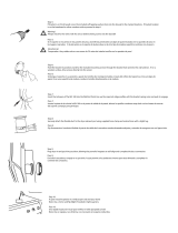
CAUTION: IMPORTANT SAFETY INSTRUCTIONS — PLEASE READ ENTIRE MANUAL PRIOR TO USE — SAVE THESE INSTRUCTIONS
Do you own a Sonos
®
PLAY:1™ or PLAY:3™ speaker?
This speaker mount is designed to support PLAY:1 and PLAY:3 speakers.
Weight Limit: 10 lb (4.5 kg)
Ready to begin?
Check your speaker owner’s manual to see if there are any special requirements for mounting your speaker.
Please read through these instructions completely to be sure you’re comfortable with this easy install process.
Do not use this product for any purpose not explicitly specifi ed by manufacturer.
Manufacturer is not responsible for damage or injury caused by incorrect assembly or use.
The wall must be capable of supporting fi ve times the weight of the speaker and mount combined.
If you do not understand these instructions or have doubts about the safety of the installation, assembly or use of this product, contact
Customer Service at 1-800-359-5520 (UK: 0800-056-2853).
Do you have all the tools needed?
Before getting started, let’s make sure this product is perfect for you!
1
2
3
Wood Stud Install
Concrete Install
Wallboard Install
Pencil Level
Screw
driver
Electric
Drill
Stud
Finder
Awl
Wood
Drill Bit
Masonry
Drill Bit
Hammer
Wallboard
Drill Bit
1/4 in.
(6.4 mm)
1/4 in.
(6.4 mm)
1/8 in.
(3 mm)

4
NOTE: Not all hardware included will be used.
WARNING: This product contains small items that could be a choking hazard if swallowed.
Before starting assembly, verify all parts are included and undamaged. If any parts are missing or damaged, do not return the damaged item to
your dealer; contact Customer Service. Never use damaged parts!
Supplied Parts and Hardware
STEP 1 Parts and Hardware STEP 2 Parts and Hardware
Wall Plate Screw
Mount
Wall Plate
Anchor
#10 x 1¾ in.
AF6 Toggler
01 x1
04 x1
02 x2
03 x2

5
STEP 3 Parts
Play:3 Interface
Cap
Play:1 / Play:3 Screw
Play:3 Interface Screw
1/4-20 x 1/2 in.
10-24 x 1/2 in.
STEP 2 Parts and Hardware (cont.)
08 x1
05 x1
06 x1
07 x1

6
2 31
1. Make sure that the placement of the wall plate
01
is not on a stud. Position the wall plate
01
at your desired height and level the wall plate
01
and mark
the hole locations.
2. Drill pilot holes using a 1/4 in. (6.4 mm) diameter drill bit.
3. Install 2 anchors
03
into the holes making sure that they are flush with the wallboard.
CAUTION: Avoid potential personal injury or property damage!
● Drywall covering the wall, must not be less than 1/4 in. (6.4 mm)
Max. 1/4 in.
(6.4 mm)
STEP 1A Attach Wall Plate to Wall
Wallboard Option
UP
01
03

7
4
4. Install the wall plate
01
with the two wall plate screws.
02
.
CAUTION: Avoid potential personal injury or property damage! Both screws
02
MUST BE firmly tightened to prevent unwanted movement of the wall
plate
01
.
Ensure the wall plate is securely fastened to the wall before continuing on to the next step.
NOTE: If needed, you can
make small level adjustments
to the wall plate
01
by
loosening the bottom screw
02
and shifting the wall
plate
01
until level. Tighten
the bottom screw
02
when
adjustments are complete.
02
01
01
02

8
2 31
1. Locate your stud. Verify and mark the center of the stud by finding the stud edges using an awl, a thin nail, or an edge to edge stud finder.
2. Position the wall plate
01
at your desired height and line up the holes with your stud center line. Level the wall plate
01
and mark the hole locations.
3. Drill pilot holes using a 1/8 in. (3 mm) diameter drill bit.
IMPORTANT: Pilot holes must be drilled to a depth of 1 ¾ in. (45 mm). Be sure to drill into the center of the stud.
● Drywall covering the wall, must not exceed 5/8 in. (16 mm)
● Minimum wood stud size: nominal 2 x 4 in. (51 x 102 mm) actual 1½ x 3½ in. (38 x 89 mm)
● Stud center must be verified
1/8 in.
(3 mm)
1 ¾ in. (45 mm)
Max. 5/8 in.
(16 mm)
CAUTION: Avoid potential personal injury or property damage!
UP
STEP 1B Attach Wall Plate to Wall
Wood Stud Option
01

9
4
4. Install wall plate
01
using two screws
02
. Tighten the screws
02
only until they are pulled firmly against the wall plate
01
.
CAUTION: Avoid potential personal injury or property damage! Both screws
02
MUST BE firmly tightened to prevent unwanted movement of the wall
plate
01
.
Ensure the wall plate is securely fastened to the wall before continuing on to the next step.
NOTE: If needed, you can
make small level adjustments
to the wall plate
01
by
loosening the bottom screw
02
and shifting the wall
plate
01
until level. Tighten
the bottom screw
02
when
adjustments are complete.
02
02
01
01

10
1. Position the wall plate
01
on the wall at your desired height. Level the wall plate
01
and mark the hole locations.
2. Drill two pilot holes using a 1/4 in. (6.4 mm) diameter masonry drill bit.
IMPORTANT: Pilot holes must be drilled to a depth of 2 in. (50 mm). Never drill into the mortar between blocks.
3. Insert two anchors
03
.
CAUTION: Be sure the anchors
03
are seated flush with the concrete surface.
● Mount the wall plate
01
directly onto the concrete surface
● Minimum solid concrete thickness: 8 in. (203 mm)
● Minimum concrete block size: 8 x 8 x 16 in. (203 x 203 x 406 mm)
2 31
1/4 in.
(6.4 mm)
2 in. (50 mm)
CAUTION: Avoid potential personal injury or property damage!
UP
STEP 1C
Attach Wall Plate to Wall
Solid Concrete or Concrete Block Option
01
03

11
4
4. Install wall plate
01
using two screws
02
. Tighten the screws
02
only until they are pulled firmly against the wall plate
01
.
CAUTION: Avoid potential personal injury or property damage! Both screws
02
MUST BE firmly tightened to prevent unwanted movement of the wall
plate
01
.
Ensure the wall plate is securely fastened to the wall before continuing on to the next step.
NOTE: If needed, you can
make small level adjustments
to the wall plate
01
by
loosening the bottom screw
02
and shifting the wall
plate
01
until level. Tighten
the bottom screw
02
when
adjustments are complete.
01
01
02
02

12
1
Attach the mount
04
to the Play:1 speaker with the Play:1 / Play:3 screw
07
.
NOTE: Speaker may be installed in either the right-side-up
position (shown) or up-side-down position, depending on need.
NOTE: Either mounting hole on the arm can be used.
STEP 2A
Attach Wall Mount to Speaker
SONOS
®
PLAY:1
04
07

13
1
3
2
1. Attach the Play:3 Interface bracket
05
to the mount
04
with the
Play:3 Interface screw
06
.
2. Fit the assembly onto the Play:3 speaker by inserting the legs of
the Play:3 Interface bracket
05
into the 4th holes from the end
and resting the bracket
05
against the speaker.
3. Secure the assembly to the Play:3 speaker with the
Play:1/Play:3 speaker screw
07
.
STEP 2B
Attach Wall Mount to Speaker
SONOS
®
PLAY:3 Vertical Option
05
04
05
04
06
07

14
1
3
2
1. Attach the Play:3 Interface bracket
05
to the mount
04
with the
Play:3 Interface screw
06
.
2. Fit the assembly onto the Play:3 speaker by inserting the legs of
the Play:3 Interface bracket
05
into the 4th holes from the end
and resting the bracket
05
against the speaker.
3. Secure the assembly to the Play:3 speaker with the
Play:1/Play:3 speaker screw
07
.
STEP 2C
Attach Wall Mount to Speaker
SONOS
®
PLAY:3 Horizontal Option
07
05
05
05
04
04
06

15
STEP 3
Mount Assembly to Wall Plate
01
08
04
Slide the speaker/wall mount assembly
onto the wall plate
01
.
Slide the cap
08
onto the mount
04
to finish the assembly.

16
Adjustments
35º
70º
132º
66º
The speakers can be rotated as desired on the mount.
The speakers can be tilted on the mount.
9.05°
30°
35°
66°
70°
132°
Play:3Play:3
Play:3
Play:1

17
THIS PAGE INTENTIONALLY LEFT BLANK

22
THIS PAGE INTENTIONALLY LEFT BLANK

23
THIS PAGE INTENTIONALLY LEFT BLANK

Milestone AV Technologies and its a liated corporations and subsidiaries (collectively, “Milestone”), intend to make this manual accurate and complete. However,
Milestone makes no claim that the information contained herein covers all details, conditions, or variations. Nor does it provide for every possible contingency in
connection with the installation or use of this product. The information contained in this document is subject to change without notice or obligation of any kind.
Milestone makes no representation of warranty, expressed or implied, regarding the information contained herein. Milestone assumes no responsibility for accuracy,
completeness or su ciency of the information contained in this document.
©2016 Milestone AV Technologies. All rights reserved. Sanus is a division of Milestone.
All other brand names or marks are used for identifi cation purposes and are trademarks of their respective owners.
Thank you for choosing Sanus! Please take a moment to let us know how we did:
SANUS • 6436 City West Parkway • Eden Prairie, MN 55344 USA 6901-002658 00
Call us: 1-800-359-5520
UK: 0800 056 2853
Leave a review: sanus.com
Email us: [email protected]
/