
IMPORTANT INSTRUCTIONS:
• Use the local electrical code approved installation when installing this product.
• The electrical parts in this kit are designed to complete the installation. Individual use of these devices may
be used in accordance to National Electric Code Requirements.
• This kit is not designed to be powered directly to the circuit panel.
• This installation is live (electrically energized) only when the supplied extension cord receptacle end is
plugged to the power inlet and the plug end is connected to a live wall outlet or surge suppressor that is
plugged into a live wall outlet.
• If you are not familiar with home wiring systems, please call a qualified electrician to install this product
• This Power Feed is not designed to be used as an extension cord outside the wall. Miss use of this power feed can
result in FIRE or DEATH by ELECTRICAL SHOCK. Please read these instructions carefully and follow ALL Directions.
Before USE:
• A Cord set Not Marked for Outdoor or outside the wall use is to be used behind a wall in an indoor wall only.
• Inspect thoroughly before installation. DO NOT USE IF DAMAGED.
• Look for number of watts on Appliance to be plugged into Power Extender.
• See the label on Power Extender for Specific Wattage.
• Insure the receptacle you intend to plug the Power Extender into is not more than 15 AMPS and connected to
the circuit panel with a 15 Amp Circuit Breaker.
• Do not plug more than the specified watts 10 Amps, 125 Vac, 60 Hz into this C7 Connector.
• Make sure Appliance is off before connecting Cord to outlet.
• Fully plug into Outlet.
• Do not remove bend or modify any metal prongs or pins of Power Extender.
• Insure Mounting devices are securely fastened to the wall and Power Extender is securely fastened to the
Mounting device.
• Fully insert plug into Outlets on all connections
• Do not use excessive force to Make Connections.
• Do not connect a three prong plug into a 2 hole cord.
• THIS IS A POLARIZED POWER FEED.
• Insure Installation meets all NEC code requirements. If unsure consult a licensed electrician.
During Use:
• Keep away from water.
• Do not use when wet.
• Keep Children and pets away from Power Jumper and IEC Cord Set
• Do not plug multiple extension cords from either end. Plug the C7 connector into the SONOS Speaker of the
“C714 Adapter” and the IEC to NEMA 5-13P cord set into the IEC Power Inlet of the “Power Extender” to a
surge protector or a live 15 amp receptacle.
• Do not over bend or apply excessive tension on either cord set plugged into the Power Jumper ends.
Product Use and Intended Application: Product shall be used in dry indoor premise or commercial wiring in
behind and permanently affixed to the interior wall, and be installed or fished in air voids, and joints, and
masonry block or tile walls where such walls are not exposed to, nor subject to, excessive moisture or
dampness. The Power Extender enables the installer to feed power to a HDTV mounted to the wall via an
extension cord plugged into the IEC end and then plugged into a live receptacle from an electrical branch wired
to the circuit panel. The product comes prewired so there is no wiring required by the installer.
Conforms to STD 514D and Certified CSA STD 22.2 No. 42.1-00
Electrical Rating: 125 VAC, 15 AMPS, 60 Hz
Minimum Conductor Size: 14 Gauge
Max Operating Temperature: 90° C
UL 2256 / UL 2459 / UL 94 V-0
Patented with multiple patents pending.
All rights reserved. Sonos is a registered trademark of Sonos, Inc.
SPECIFICATIONS:
Model Similarities – Length and Color, Black and White, 15’, 25’, 40’; C714 SONOS Electrical Rating 10 Amp, 125 Vac, 60
Hz, 14 AWG Conductor to a IEC 60320 CY14 power inlet. Power Jumper Assembly Insulated Cable meets UL 514D, CSA
STD 22.2 4 2.1-00 Power Jumper Assembly meets NEC Code: 250.146(D), Isolated Receptacles, Interconnect meets UL
2256 and UL 2459, Adapter C714 meets UL498:2012 ed. 15 +R: 07 Jul2016, CSA2C22.2@21:2014 Ed.9 +A1, Power
Jumper Assembly Cable, Type NM-B (Non-metallic sheathed cable) has a broad range of usage as defined in Article 334
of the National Electrical Code (NEC). The Power Jumper is compatible to NEC Article 300.15 (E) Integral Enclosure and
NEC 334.40 (B) Devices of Insulating Material and other NEC code requirements suitable for it intended application. All
connector material used in the Power Jumper Cable assembly (Polycarbonate) are rated UL 94 V-0, for its intended
application.
14-2 Premise Wire Type NM-B cable may be used for both exposed and concealed work in normally dry locations at
temperatures not to exceed 90°C (with ampacity limited to that for 60°C conductors) as specified in the National
Electrical Code. NM-B cable may be run in air voids of masonry block or tile walls where such walls are not subject to
excessive moisture or dampness. Voltage rating for NM-B cable is 600 volts.
WARNING
MIDLITE® products shall be installed and used only as indicated in MIDLITE® product instruction sheets.
Instruction sheets are available online at www.midlite.com.
CAUTION
For shock protection, this device must be properly grounded. Use copper wire only with this device.
Risk of Fire -- Do Not Install Power Supply Cord within the Wall Cavity, or the equivalent.
Risk of Fire and Shock. Do not connect this box to any other circuits or outlets or the equivalent.
IMPORTANT INSTRUCTIONS
Read and understand all instructions. Follow all warnings and instructions marked on the product. Remember this
product is not part of your home’s electrical wiring system Do not install in areas near water such as swimming
pools, baths, sinks, showers, tubs and wet basements.
SAVE THESE INSTRUCTIONS.
PN: C7HS-X-WIP-XX
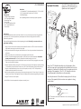
SPEAKER
RUBBER BUMPER
SPEEDPORT
WITH SCREW CAP
AND 1/4”-20 STUD
OVERMOLDED C714
HANDLE
2” HOLE
(HOLE SAW)
WIP End to be terminated
in an electrical box
Available in lenghts of
15’, 25’, or 40’
All rights reserved. Sonos is a registered trademark of Sonos, Inc.
3
1
2
102319
Screwcap Assembly


 1
1
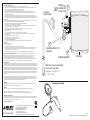 2
2


Nedis Speaker Wall Mount Installation guide
 OTE Speedport W 724V Type Ci Cosmote Owner's manual
Deutsche Telekom 40258947 Datasheet
 Tenvis JPT3812 Owner's manual
Digitus DN-18602 Quick start guide
Hyundai A1227 Datasheet
Auerswald COMpact 3000 analog Quick Start Instructions
Fujitsu Modem FC9660RA12 User manual
Sonos Playbar User manual

