Page is loading ...

Features
Control panel operator convenience features:
Wide viewing angle 2 x 20 (40 character) alphanumeric
LCD and dedicated LEDs provide convenient panel
status information
Operation is programmable using a multi-function
keypad and the panel LCD or via service computer (PC)
RS-232 service port provides upload/download PC
access for panel configuration and event history logs
Software updates are via PC download
Convenient library of standard custom label terms
Standard on-board DACT provides: Contact ID, 3/1, 4/2,
BFSK, and SIA formats
WALKTEST silent or audible system test
Voltage and current for both the battery charger and the
battery can be displayed at the front panel LCD
Five Standard Initiating Device Circuits (IDCs):
Five Class B IDCs with optional expansion to ten, all
with individual zone disable
Monitor 2-wire or 4-wire initiating devices including
TrueAlarm smoke detectors
Optional Class A Adapter Module
Two Standard Notification Appliance Circuits (NACs):
Class A or Class B outputs with solid state overcurrent
protection per NAC, each rated for 2 A
Selectable for Simplex
®
SmartSync two-wire
horn/strobe control or synchronized strobe control
Standard Power Supply:
Provides 3 A maximum @ nominal 24 DC
Automatic input power selection operates with 120 VAC
or 240 VAC, 50 or 60 Hz
On-board temperature compensated battery charger for
up to 12.7 Ah batteries in cabinet (UL and ULC) and up
to 25 Ah batteries in separate cabinet (UL only)
Additional standard features:
Programmable Active Status Reminder
Two auxiliary relays
IDCs, NACs, and Relay outputs are power limited (AC
input, battery circuits, and City Circuit Module outputs
are non-power limited)
Available with beige or red cabinet
UL listed to Standard 864
Available option modules:
Door mounted 24 LED annunciator (standard on ULC
models)
3 A Expansion Power Supply with two on-board 2 A
NACs that operate the same as standard NACs
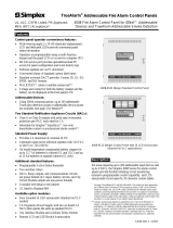
ALARM
ACK
SUPV
ACK
TROUBLE
ACK
ALARM
SILENCE
SYSTEM
RESET
FIRE
ALARM
SYSTEM
SUPERVISORY
SYSTEM
TROUBLE
ALARM
SILENCED
AC
POWER
4006-9102 (Beige) Standard Control Panel
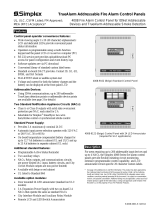
ALARM
ACK
SUPV
ACK
TROUBLE
ACK
ALARM
SILENCE
SYSTEM
RESET
FIRE
ALARM
SYSTEM
SUPERVISORY
SYSTEM
TROUBLE
ALARM
SILENCED
AC
POWER
Fire Alarm Annunciator
CAUTION
DISCONNECT
BATTERY AND
A. C. POWER
BEFORE
SERVICING
4006-9122 (Beige) Control Panel with 24 LED Annunciator
Available option modules (Continued):
Expansion IDC module with five Class B IDCs
Class A IDC Adapter Module, City Interface Module,
and Auxiliary Relay Module
Remote LCD and LED/Switch Annunciators
Description
For areas requiring from five to ten initiating zones, the
Simplex 4006 Series fire alarm control panels provide
flexible initiating circuit monitoring, extensive
programmable control capability, and LCD annunciated
circuit-specific 20 character custom labels.
*
See page 2 for additional ULC and MEA information. This product has been approved by
the California State Fire Marshal (CSFM) pursuant to Section 13144.1 of the California
Health and Safety Code. See CSFM Listing 7165-0026:318 for allowable values and/or
conditions concerning material presented in this document. It is subject to re-examination,
revision, and possible cancellation. Additional listings may be applicable, contact your local
Simplex product supplier for the latest status. Listings and approvals under Simplex Time
Recorder Co. are the property of Tyco Fire Protection Products.
LifeAlarm Fire Alarm Control Panels
UL, ULC, CSFM Listed; FM Approved; 4006 Series Fire Alarm Control Panels
MEA (NYC) Acceptance* Providing up to Ten IDCs and Four NACs
S4006-0001-9 2/2016

Standard Feature Details
Five Class B IDCs are each capable of supporting up to 30
Simplex current-limited smoke detectors or electronic heat
detectors (see list on page 4) as well as manual stations and
other compatible contact closure initiating devices. IDCs
are capable of Class A operation with an optional adapter
module and can be programmed as Style C (short or open
initiates a trouble) for use with current limited devices only.
Two, 2 A On-Board NACs provide conventional reverse
polarity operation, selectable as Class A or Class B, with
electronic control and overcurrent protection. Operation is
selectable for synchronized strobe or SmartSync horn/strobe
two-wire operation. Horn control can be selected at the panel
for: Temporal pattern coding, Steady On, Slow March Time
of 20 beats per minute (BPM), or Fast March Time of
120 BPM. Note: When selected for SmartSync horn/strobe
control, March Time produces 60 BPM.
The 24 VDC Auxiliary output provides up to 500 mA
for system use. (Auxiliary output current is counted for
total power supply capacity.)
Standard Auxiliary Relay Outputs. Two relay outputs
are available, selectable as normally open or normally
closed, rated 2 A @ 30 VDC per below:
Aux Relay 1 is normally assigned to General Alarm
operation but is programmable (see page 7)
Aux Relay 2 (Trouble) is energized when Normal and is
de-energized with a Trouble condition.
On-Board Dual Line DACT. Operation can be selected
for Contact ID, SIA, 3/1, 4/2, and BFSK formats.
Reporting includes Alarm, Supervisory, Trouble, and AC
Failure. Operation includes automatic 6 hour test and
programmable power fail report delay.
Standard Feature Details (Continued)
Power Supply and Battery Charger. DC power output
is 3 A @ 24 VDC for panel use. The temperature
compensated battery charger (sealed lead-acid batteries
only) is rated for up to 25 Ah batteries per UL 864 and up
to 12.7 Ah per ULC-S527. (Up to 12.7 Ah batteries fit in
the cabinet, larger batteries require an external cabinet.)
Panel electronics can measure and display voltage and
current for the power supply, batteries and the battery
charger (standard and expansion power supply). Depleted
battery trouble is monitored and annunciated and depleted
battery cutout can be selected. Active battery status
monitor supervises charger operation.
Optional Feature Details
Expansion Power Supply. Provides 3 A total @
24 VDC, two additional 2 A NACs, and an additional
auxiliary power output of 500 mA. Output operation is the
same as on the standard power supply.
Expansion IDC Module. Provides 5 additional Class B
IDCs with operation the same as the standard IDCs.
Expansion Relay Module. Provides 10 programmable
relays, jumper selectable as N.O. or N.C. Contacts are
rated 2 A @ 30 VDC. Typical application is to track
status of each IDC. See page 7 for relay program options.
Class A Adapter Module. Converts 5 IDCs from
Class B to Class A operation. Two modules can be
mounted for use with the Expansion IDC Module.
City Circuit Modules. These modules are available with
or without on-board disconnect switches, depending on
local requirements (either type can be disconnected
through the front panel under password control).
Connections are for Remote Station (reverse polarity) or
Municipal Master (local energy). Reporting includes
Alarm, Supervisory, and Trouble.
2 S4006-0001-9 2/2016
Control Panel
Model Color Description Listings Standard Feature Summary
4006-9102 Beige
Standard fire alarm control panel MEA
UL, FM,
& CSFM
5 Class B IDCs, 2 Class B/Class A
NACs, 3 A power supply with battery
charger; on-board DACT; 120/240 VAC,
50/60 Hz (autoselect)
4006-9101 Red
4006-9122 Beige
Fire alarm control panel with 24 LED
Annunciator on front door
ULC
4006-9121 Red
Option Modules
Model Description
4006-9801 Expansion Power Supply; 3 A, with 2 NACs, 120/240 VAC, 50/60 Hz
Select up to one of each as required
4006-9802 Expansion IDC Module; 5 Class B IDCs
4006-9803 Expansion Relay Module; 10 relays selectable as either N.O. or N. C.
4006-9804 Class A Adapter Module; converts 5 IDCs from Class B to Class A Select up to two maximum
4006-9805 City Circuit Module with disconnect switch
Select one if required
4006-9806 City Circuit Module without disconnect switch
Accessories
Model Description
2975-9811 Beige semi-flush trim kit; 1-7/16” (37 mm) wide; includes four corners and trim pieces for top, bottom, and sides
2975-9812 Red semi-flush trim kit; 1-7/16” (37 mm) wide; includes four corners and trim pieces for top, bottom, and sides
4009-9801
Beige External Battery Cabinet for up to 25 Ah batteries; mounts close-nippled to control panel cabinet; dimensions =
16-1/4” W x 13-1/2” H x 5-3/4” D (413 mm x 343 mm x 146 mm) [depth increased for 25 Ah effective 7/2005]
Batteries, 12 Volt (select one battery model per system standby requirements; order quantity of two)
Model Size Model Size Location Model Size Location
2081-9272 6.2 Ah 2081-9288 12.7 Ah
For cabinet mount
2081-9275 18 Ah
Requires 4009-9801 External Battery
Cabinet (UL listed only)
2081-9274 10 Ah 2081-9827 25 Ah
Product Selection

ALARM
ACK
SUPV
ACK
TROUBLE
ACK
ALARM
SILENCE
SYSTEM
RESET
FIRE
ALARM
SYSTEM
SUPERVISORY
SYSTEM
TROUBLE
ALARM
SILENCED
AC
POWER
1
ABC
2
DEF
3
GHI
4
JKL
5
MNO
6
PQRS
7
TUV
8
WXYZ
9
0
MENU
PREVIOUS
NEXT
ENTER
FUNCTION
DISABLE
ENABLE
EXIT
CLEAR
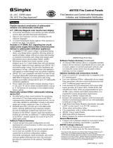
FIVE STATUS INDICATOR LEDs provide system status indications in
addition to LCD information, LEDs flash to indicate the condition and
then when acknowledged, remain on until reset
2 X 20 LCD READOUT, LED backlighted during normal conditions and abnormal
operating conditions, provides up to 20 characters for custom label information
FIRST ALARM DISPLAY: Operation can be selected for maintained display of first
alarm until acknowledged
THREE PROGRAMMABLE LEDs
provide custom labeling (labels insert into
a pocket), the top two LEDs are
selectable as red or yellow, the bottom
LED is selectable as green or yellow
CONTROL
PANEL VIEW
with door closed
ALARM SILENCE causes audible notification appliances
to be silenced, used after evacuation is complete and
while alarm source is being investigated
SYSTEM RESET restores
control panel to normal when
all alarmed inputs are
returned to normal
ALARM ACK acknowledges a Fire
Alarm condition, logs the
acknowledge, silences the operator
panel and all annunciator tone-alerts,
and steps through the active Alarm list
SUPV ACK acknowledges system
supervisory conditions, logs the
acknowledge, silences the operator
panel and all annunciator tone-alerts,
and steps through the active
Supervisory list
TROUBLE ACK acknowledges
system troubles, logs the
acknowledge, silences the
operator panel and all annunciator
tone-alerts, and steps through the
active Trouble list
FIVE NAVIGATION KEYS: MENU selects
the on-screen programming menu; left and
right arrows moves the position on the
screen, and PREVIOUS and NEXT
navigate screen selections
ALPHANUMERIC
KEYPAD provides
programming entry of
numbers and letters
FOUR EXTENDED FUNCTION KEYS: ENTER confirms
selections, EXIT/CLEAR backs out of the present screen menu
and clears information that has not been entered, FUNCTION
enables the active function menu, DISABLE/ENABLE toggles
the function or circuit status as appropriate per the selected
screen
3 S4006-0001-9 2/2016
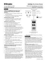
Fire Alarm Annunciator
RED LED
YELLOW LED
IDC 1
IDC 2
IDC 3
IDC 4
IDC 5
IDC 6
IDC 7
IDC 8
IDC 9
IDC 10
NAC 1
NAC 2
NAC 3
NAC 4
14 CUSTOM LABEL AREAS are available, typically for IDC
and NAC annunciation (shown labeled for reference, blank
labels are provided); dual LED locations have a Red LED
(top) and a Yellow LED (bottom); labels insert into pockets
behind the overlay; LED operation is programmable to track
other monitored status conditions
FOUR YELLOW LEDs provide
default NAC Trouble annunciation
(shown labeled as NAC 1-4)
Keyboard Reference
Door LED Annunciator Details

4 S4006-0001-9 2/2016
Power Ratings
AC Input Ratings
Input Voltage 120 VAC, 60 Hz; 220/230/240 VAC, 50/60 Hz, auto-select
Input Current, Standard 2 A maximum @ 120 VAC input; 1.5 A maximum @ 240 VAC input
Input Current with
Expansion Power Supply
4 A maximum @ 120 VAC input; 3 A maximum @ 240 VAC input
Power Supply Output Rating 3 A maximum @ 24 VDC in alarm (see NAC details on page 6)
Battery Charger
Temperature compensated charger is rated for up to 25 Ah per UL 864; up to
12.7 Ah per ULC-S527
Standby Current 130 mA; with 5 IDCs fully loaded, tone-alert silenced, trouble LED on
Standard Circuit Ratings (NOTE: Total DC current = 3 A maximum)
Notification Appliance Circuits (NACs)
NOTE: See details on page 6
2 A maximum @ 24 VDC, per circuit; available as Class A or Class B;
Class B end-of-line resistor = 10 k, 1/2 W; Model 4081-9008 (P/N 733-894)
Initiating Device
Circuits (IDCs)
Supervisory Current 3 mA maximum
Alarm Current 60 mA maximum
Capacity
Each IDC supports up to 30 detectors (smoke or electronic heat) and manual
stations as required; wiring distance is limited to 50 Ω maximum
End-of-Line Resistor 3.3 k, 1/2 W; Model 4081-9002 (P/N 733-893) for Class B IDCs
Annunciator
Communications
Quantity Supported Up to four annunciator modules per panel (see page 5 for details)
Wiring Type Twisted pair, or twisted, shielded pair; 18 AWG (0.82 mm
2
)
Bus-Style Wiring Up to 4000 ft (1219 m); 0.58 µF (580 nF) maximum capacitance; 35 max.
“T-Tap” Wiring Up to 10,000 ft (3048 m) total wiring; up to 2500 ft (762 m) to farthest device
Line Matching Resistor
Bus-style, connect one at panel and one at end of line
100 , 1/2 W; 4081-9011;
(part number 733-974)
T-Tap, connect one at panel and one at farthest device
Suppression
Use 2081-9044 Overvoltage Protectors where wiring leaves and enters a building
(refer to data sheet S2081-0016)
Auxiliary Power Output 500 mA maximum @ 24 VDC
Standard Auxiliary Relay Outputs
Relay 1 Programmable operation
Contacts rated 2 A @ 30 VDC, 0.35 power factor;
jumper selectable as N.O. or N.C.
Relay 2 Trouble operation
Wiring Connections for Above Circuits and
AC Input
Terminals rated for 18 AWG to 12 AWG (0.82 mm
2
to 3.31 mm
2
)
Option Module Ratings
Class A IDC Adapter Module Five circuits per module, rated same as circuits
Ten Relay Auxiliary
Module 4006-9803
Contact Ratings 2 A @ 30 VDC, 0.35 power factor; jumper selectable as N.O. or N.C.
Wiring Terminals rated for 18 AWG to 12 AWG (0.82 mm
2
to 3.31 mm
2
)
Environmental Ratings
Operating Temperature Range 32° to 120°F (0° to 49° C)
Operating Humidity Range Up to 93% RH, non-condensing @ 100.4° F (38° C) maximum
Compatible Simplex Detectors
Model Type Description Data Sheet
4098-9601
Photoelectric smoke detectors
for 2-wire and 4-wire bases
Standard detector (2.8% nominal)
S4098-0015
4098-9605 Reduced sensitivity detector (3.5% nominal)
4098-9602 Combination smoke and heat detector S4098-0017
4098 Series Duct detector housings 2-wire and 4-wire models S4098-0029
4098 Series Ionization Smoke Detectors 2-wire and 4-wire models S4098-0018
4098-9612
Electronic heat detectors for
2-wire and 4-wire bases
135° F (57°C)
Fixed temperature heat detector
S4098-0014
4098-9614 200° F (93°C)
4098-9613 135° F (57°C)
Fixed temperature heat detector with
rate-of-rise detection
4098-9615 200° F (93°C)
Compatible System Expansion Panels
Model Type Description Data Sheet
4003 Series Voice Control Panel
Provides a remote voice control panel with on-board NACs, internal
microphone, and remote microphone input
S4003-0002
4009 Series Remote NAC Extender
Provides remote NACs; includes power supply and battery charger;
4 extenders max/NAC; 4006 uses NAC output to provide control
S4009-0002
Note: Contact your local Simplex Product Supplier for additional compatible peripherals.
Specifications (Refer to Installation Instructions 579-704 for additional information)
Reference Information, Compatible Simplex Peripherals

The 4006 supports up to four annunciator options
including:
Door Mounted 24 LED Annunciator
4610-9111 Remote LED/Switch Annunciators
4606-9101 Remote LCD Annunciators
Annunciators communicate at a rate of 9600 baud with
24 VDC power supplied by separate wiring.
4610-9111 LED Annunciator Features:
16 LEDs with programmable functions and dedicated
LEDs for Alarm Silenced, Lost Communications,
Trouble, and Power-on
Keyswitch access controlled switches for
Acknowledge, Alarm Silence, Reset, and Lamp Test
Local tone-alert
4610-9111 LED/Switch Annunciator
4606-9101 LCD Annunciator Features:
LCD readout with two lines of 40 characters each and
LED backlighting
Wide viewing angle, super-twist design
Keyswitch access controlled
Control switches and status LEDs for:
Alarm, supervisory, or trouble acknowledge
Alarm silence and System Reset
Three programmable LED indicators:
Two LEDs are selectable as red or yellow
One LED is selectable as green or yellow
With provisions for custom labeling
4606-9101 LCD Annunciator
5 S4006-0001-9 2/2016
Model Module Supervisory Alarm
4006-9101
4006-9102
Standard fire alarm control panel 130 mA
160 mA
+ 60 mA per IDC in Alarm
4006-9121
4006-9122
Control panel with 24 LED Annunciator 148 mA
210 mA
+ 60 mA per IDC in Alarm
4006-9801 Expansion Power Supply 50 mA 60 mA
4006-9802 Expansion IDC Module 50 mA
50 mA
+ 60 mA per IDC in Alarm
4006-9803 Expansion Relay Module
0 mA
+ 10 mA per energized relay
0 mA
+ 10 mA per energized relay
4006-9804 Five Circuit IDC Class A Adapter
0 mA normal;
10 mA per IDC in trouble
0 mA normal;
10 mA per IDC in trouble
4006-9805
City Circuit Module with disconnect switch
30 mA 60 mA
4006-9806
City Circuit Module without disconnect switch
30 mA 60 mA
4606-9101
Remote LCD Annunciator (see data sheet
S4606-0001)
65 mA 140 mA
4610-9111
Remote LED/Switch Annunciator (see data
sheet S4610-0001)
40 mA
70 mA
(all LEDs and tone-alert on)
** Current Calculation Information:
1. To determine total supervisory current, add currents of modules in panel to base system value and all auxiliary loads.
2. To determine total alarm current, add currents of modules in panel to base system alarm current and add all panel NAC loads
and all auxiliary loads.
Fire Alarm Annunciator
ACK
RESET
ALARM
SILENCE
LAMP
TEST
ALARM
SILENCED
LOST COM
TROUBLE
POWER
CONTROL
ENABLE
FIRE
ALARM
ALARM
SILENCED
SYSTEM
SUPERVISORY
SYSTEM
TROUBLE
POWER
ON
SYSTEM
RESET
ALARM
ACK
SUPV
ACK
TBL
ACK
ALARM
SILENCE
Supervisory and Alarm Currents
Remote Annunciator Options

The following IDC operation modes are selectable from either the front panel or the PC programmer
6 S4006-0001-9 2/2016
Function Type Description Device State IDC Status
FIRE Fire monitor zone
Normal =
Current Limited =
Short =
Open =
NORMAL
FIRE
FIRE
TROUBLE
WATER Waterflow monitor zone
Normal =
Current Limited =
Short =
Open =
NORMAL
FIRE
FIRE
TROUBLE
HEAT Heat detector zone
DUCT Duct detector zone
PULL Manual (pull) station zone
SMOKE Smoke detector zone
SO Sprinkler Supervisory
Normal =
Current Limited =
Short =
Open =
NORMAL
SUPERVISORY
SUPERVISORY
TROUBLE
WSO
Combination waterflow and water supervisory
zone
Normal =
Current Limited =
Short =
Open =
NORMAL
SUPERVISORY
ALARM
TROUBLE
SUPV Supervisory monitor
Normal =
Current Limited =
Short =
Open =
NORMAL
SUPERVISORY
SUPERVISORY
TROUBLE
UTIL Supervised utility monitor
Normal =
Current Limited =
Short =
Open =
OFF
ON
ON
TROUBLE
TROUBLE Trouble monitor
Normal =
Current Limited =
Short =
Open =
NORMAL
TROUBLE
TROUBLE
TROUBLE
VSMOKE
Verified fire alarm; the abnormal (current limited)
state causes the alarm verification cycle to start;
a short is an immediate alarm
Normal =
Current Limited =
Short =
Open =
NORMAL
VERIFY
FIRE
TROUBLE
STYLEC Style C fire monitor
Normal =
Current Limited =
Short =
Open =
NORMAL
FIRE
TROUBLE
TROUBLE
LATSUPV
Latching supervisory monitor (supervisory
latches until system is reset)
Normal =
Current Limited =
Short =
Open =
NORMAL
SUPERVISORY
SUPERVISORY
TROUBLE
NAC Ratings, Maximum per NAC Appliances
Special Application: 2 A;
strobe synchronization is UL listed across all 4
system NACs for these 4906 Series appliances
Simplex 4901 Series (horns) and 4906 Series Multi-Candela non-addressable
strobes, horn/strobes, and speaker/strobes (contact your Simplex product
representative for compatible appliances)
Regulated 24 VDC: 1.5 A
NOTE: Maximum strobe load on main power
supply or expansion power supply is 1.35 A per
power supply (2.7 A total); remainder of power
supply rating is available for other loading
Power for other UL listed appliances; use associated external synchronization
modules where required
IDC Operation Modes
Detailed NAC Ratings

Function Type Description
SSIG Alarm signal, on until silenced
RSIG Alarm signal, on until reset
TROUBLE Trouble signal
SUPV Supervisory signal
QALERT SmartSync 2-wire horn/strobe control; horn on until silenced, strobe on until reset
WHEELOCK
Provides Wheelock strobe synch protocol when using only Wheelock strobes on panel, not to be mixed with
Simplex strobes
UTILITY Utility signal, generic non-alarm
7 S4006-0001-9 2/2016
Common Fire Alarm Operations
Function Type Relay Activates Upon Relay Deactivates Upon
SRELAY General Alarm Silence
RRELAY General Alarm Reset
SUPV Supervisory condition Clear
TRBL Trouble condition Clear
Special Functions
Function Type Description
UTILITY Utility IDC in the same alarm group activates
PRIMARY General alarm; relay is tied to Primary Elevator Recall contacts
ALTERN General alarm; relay is tied to Alternate Elevator Recall contacts
DRESET Relay provides 24 VDC power to 4-wire detectors; relay turns off for 5 seconds on System Reset
DHOLDER
Relay provides 24 VDC to larger door holder relay with separate power source; relay activates on general
alarm to remove power to door holder relay and close doors
Function Details
Custom labels
Up to 20 characters per point; a built-in message library provides for commonly used words for easy front
panel programming
Message Library
For front panel label creation convenience, the following words can be selected as part of a custom label
( _designates a built-in space; typing the first letter of a word/number will select the closest word in
alphabetical/numerical sequence)
North
South
East
West
Front
Center
rear
5th
Flr_1
Flr_2
Flr_3
Flr_4
Flr_5
RM_
Basement
Floor
Garage
Hallway
HVAC_Room
Kitchen
Lobby
Office
Patient
upper
lower
main
first
2nd
3rd
4th
Boiler_RM
Classroom
Closet_
Corridor
Elect_RM
Elevator
Entrance
Restroom
Room
Stairway
Storeroom
Wing
Zone
History logs
Three separate logs: Alarm (100 entries), Supervisory (100 entries), and Trouble (300 entries); logs can be
queried separately, or as a combined log; logs can be downloaded for printing or archiving using the RS-232
service port
Autoprogram
Automatically scans system for installed option modules and configures panel programming accordingly;
modes are available to detect new modules only, recreate default programming and then add all modules
found
Alarm Groups
Up to 99 alarm groups are available, any point may be in up to 3 alarm groups; this allows NAC and relay
operation to be associated with IDC inputs according to local response requirements
WALKTEST
Allows one person to perform system testing; alarm or trouble tests are followed by automatic reset; the alarm
zone is sounded out by associated audible notification or the response is silently logged into the Alarm log
Manual Control Allows selection of individual relays or NACs for system testing
Passcode
Protection
(4-digit number)
Level 1 = Acknowledge, Silence, System Reset, View logs, View point information, and Lamp Test
Level 2 = All Level 1 + Set Time/Date, Point Control, Enable/Disable points
Level 3 = All Level 2 + Clear logs, Clear verification tallies, Custom label editing, and WALKTEST
Level 4 = All Level 3 + Programming, Upload/Download; this is the Service access level
Relay Operation Modes
The following relay operations are selectable from either the front panel or the PC programmer.
Additional Programming Feature Details
NAC Operation Modes

Box width 15-5/8" (397 mm)
(Top and side views are
shown with door installed)
* Indicates optional modules
11-1/4" (286 mm)
13-1/2"
(343 mm)
13-1/4" (337 mm)
Battery Area
No conduit or wiring in this area
AC Input Terminals City Module*
ALARM
ACK
SUPV
ACK
TROUBLE
ACK
ALARM
SILENCE
SYSTEM
RESET
FIRE
ALARM
SYSTEM
SUPERVISORY
SYSTEM
TROUBL E
ALARM
SILENCED
AC
POWER
1
ABC
2
DEF
3
GHI
4
JKL
5
MNO
6
PQRS
7
TUV
8
WXYZ
9
0
MENU
PREVIOUS
NEXT
ENTER
FUNCTION
DISAB LE
ENABLE
EXIT
CLEAR
Class A
Adapter
Modules*
IDC Expansion
Module*
Main board
Relay
Expansion
Module*
Main board
Knockouts are
located on top
and sides
Expansion
Power Supply*
(extends under
IDC Expansion
Module space)
Display
Assembly
Box depth = 4-3/4" (121 mm)
16"
(406 mm)
Door thickness
5/8" (16 mm)
NOTE: For semi-flush mounting, cabinet
must extend 1-1/2" (38 mm)
minimum from wall surface
Tyco Fire Protection Products • Westminster, MA • 01441-0001 • USA S4006-0001-9 2/2016
www.simplexgrinnell.com
© 2012 Tyco Fire Protection Products. All rights reserved. All specifications and other information shown were current as of document revision date and are subject to change without notice.
TYCO, SIMPLEX, and the product names listed in this material are marks and/or registered marks. Unauthorized use is strictly prohibited.
Installation and Module Placement Reference
/