Page is loading ...

579-409
Rev. Q


©2005, 2006, 2008, Tyco Safety Products Westminster, MA 01441-0001 USA.
All rights reserved.
All specifications and other information shown were current as of document
revision date, and are subject to change without notice.
Printed in the United States of America.
Simplex and the Simplex logo are registered trademarks of Tyco International
Ltd. and its affiliates and are used under license.
Tyco is a registered trademark of Tyco International Services GmbH and is used
under license.
Microsoft is a registered trademark of Microsoft Corporation.
Windows is a trademark of the Microsoft Corporation.
All other logos and product names are trademarks or registered trademarks of
their respective companies.
Copyright and Trademarks
Copyright
Trademarks

SYSTEM REACCEPTANCE TEST AFTER SOFTWARE CHANGES -
To ensure proper system operation, this product must be tested in accordance
with NFPA 72 after any programming operation or change in site-specific
software. Reacceptance testing is required after any change, addition or deletion
of system components, or after any modification, repair or adjustment to system
hardware or wiring.
All components, circuits, system operations, or software functions, known to be
affected by a change, must be 100% tested. In addition, to ensure that other
operations are not inadvertently affected, at least 10% of initiating devices that
are not directly affected by the change, up to a maximum of 50 devices, must
also be tested and proper system operation verified.
DO NOT INSTALL ANY SIMPLEX PRODUCT THAT APPEARS
DAMAGED. Upon unpacking your Simplex product, inspect the contents of
the carton for shipping damage. If damage is apparent, immediately file a claim
with the carrier and notify your local Simplex product supplier.
ELECTRICAL HAZARD - Disconnect electrical power when making any
internal adjustments or repairs. All repairs should be performed by qualified
technical representatives.
RADIO FREQUENCY ENERGY
This equipment has been tested and found to comply with the limits for a Class
A digital device, pursuant to Part 15 of the FCC Rules. These limits are
designed to provide reasonable protection against harmful interference when the
equipment is operated in a commercial environment. This equipment generates,
uses, and can radiate radio frequency energy and, if not installed and used in
accordance with the instruction manual, may cause harmful interference to radio
communications. Operation of this equipment in a residential area is likely to
cause harmful interference in which case the user will be required to correct the
interference at his or her own expense.
NFPA 72 is a registered trademark of the National Fire Protection Association.
Cautions and Warnings
System Reacceptance Test

iii
How to Use this Publication ..................................................................vi
Conventions Used .............................................................................vi
Keyboard Conventions ......................................................................vi
Text Conventions..............................................................................vii
Using the Mouse...............................................................................vii
Chapter 1 Before You Begin...........................................................1-1
Introduction.....................................................................................1-1
In this Chapter ................................................................................1-1
Getting Started...................................................................................1-2
Unpack the Equipment ...................................................................1-2
Inspect the Equipment....................................................................1-2
Inventory the Equipment.................................................................1-2
Related Documentation..................................................................1-2
Chapter 2 Installing the Hardware .................................................2-1
Introduction.....................................................................................2-1
In this Chapter ................................................................................2-1
System Requirements........................................................................2-2
System Requirements for Windows 2000 Computers ...................2-2
Additional Hardware Requirements (Central Station Receiving Fire
Applications)...................................................................................2-2
Sur-Guard System III DACR/IMS Limitations.................................2-2
Electrical Input Ratings...................................................................2-3
Positioning the Equipment .................................................................2-4
Considerations................................................................................2-4
Connecting the IMS to the System.....................................................2-5
Connecting the Equipment.............................................................2-5
Connecting a Touchscreen Monitor ...............................................2-7
Connecting the Mouse....................................................................2-7
Connecting the Keyboard...............................................................2-7
Connecting the Software Key.........................................................2-7
Connecting the Printer (Optional)...................................................2-7
Connecting the Optional Uninterruptible Power Supply (UPS)......2-8
Connecting to a Network................................................................2-8
Chapter 3 Installing the IMS Software ...........................................3-1
Introduction.....................................................................................3-1
In this Chapter ................................................................................3-1
Software Requirements......................................................................3-2
IMS Requirements..........................................................................3-2
Optional Software...........................................................................3-2
Installing the Software........................................................................3-3
Installing Windows 2000.................................................................3-3
Installing Serial Touchscreen Software..........................................3-4
Calibrating Touchscreen Software .................................................3-4
Installing the Optional Tape Drive Software from Floppy Disk.......3-5
Installing the Optional Tape Drive Software from CD-ROM...........3-6
Editing the Windows WIN.INI file for Optional Tape Drive .............3-6
Installing the Security Service ........................................................3-6
Installing the 4190 IMS Software....................................................3-7
Contents

iv
Requiring or Disabling Logon Password in Workgroup Setting.....3-8
Installing and Operating the SPC 2120 Utility (RETROFIT
APPLICATION ONLY)........................................................................3-9
Introduction.....................................................................................3-9
Requirements .................................................................................3-9
Installation Procedure.....................................................................3-9
Operating the SPC 2120 Utility.....................................................3-10
Configuring the Computer Ports.......................................................3-11
Port Configuration Procedure.......................................................3-11
Adding 2120 Points (RETROFIT APPLICATIONS ONLY) ..............3-14
How to Add 2120 Points to the Point Database and Network......3-14
Configuring the IMS to Communicate with DACRs..........................3-16
Adding the DACR Port..................................................................3-16
Adding DACR Accounts and Points .............................................3-16
Adding the Event Account............................................................3-16
Entering Points Manually..............................................................3-16
Importing CID Points.....................................................................3-17
4190 IMS Checkout..........................................................................3-18
How to Checkout the IMS.............................................................3-18
Testing Circuit Supervision...........................................................3-18
Chapter 4 Installing the IMS Rack-Mount Versions......................4-1
Introduction.....................................................................................4-1
In this Chapter ................................................................................4-1
Installing the Rack-Mount Components.............................................4-2
Installation Procedure.....................................................................4-2
Chapter 5 Connecting 2120 Nodes and DACRs (RETROFIT
APPLICATIONS ONLY)........................................................................5-1
Introduction.....................................................................................5-1
In this Chapter ................................................................................5-1
Hardware Requirements....................................................................5-2
Required Cables and Connectors ..................................................5-2
Connecting the 2120 Nodes to the IMS (Retrofit Applications Only).5-3
Installing with Adapter Cable..........................................................5-3
Installing without Adapter Cable.....................................................5-5
Connecting DACRs to the IMS...........................................................5-6
Installing with Adapter Cable..........................................................5-6
Installing MLR-2DG-DACR without adapter...................................5-8
Configuring System III DACR Options..........................................5-10
Configuring Bosch 6600 DACR Options ......................................5-10
Chapter 6 Jumpers, Interrupts, and Switch Settings...................6-1
Introduction.....................................................................................6-1
In this Chapter ................................................................................6-1
Interrupt (IRQ) Settings......................................................................6-2
Recommended Interrupt (IRQ) Settings.........................................6-2
IMS IRQ Settings............................................................................6-2
Possible IRQ Settings.....................................................................6-3
Jumper Settings .................................................................................6-4
RS-232 Media Card (P/N 565-327)...............................................6-4
Wired Media Card (P/N 565-413)...................................................6-4
Fiber Optic Media Assembly...........................................................6-4

v
Switch Settings...................................................................................6-5
UL Card (P/N 565-283)...................................................................6-5
Configuring the Devices.....................................................................6-6
Configuring Device Drivers for Windows 2000...............................6-6
Quad Serial Port Card ....................................................................6-6
Interfacing with the 4120 Network......................................................6-7
Network Interface Card...................................................................6-7
Installing Cards and Jumpers.............................................................6-8
Inserting and Connecting Cards in the IMS....................................6-8
4190-8103 ⎯ Card Slot Positions..................................................6-8
Continuity Check for Model 4190-8103 with UL Card Installed......6-9
Verifying the Tape Drive Installation ................................................6-10
Verifying Tape Drive Installation (Optional)..................................6-10
Disabling the Reboot Watchdog.......................................................6-11
Reboot Watchdog.........................................................................6-11

vi
Before you start using the 4190 Information Management System Installation
and Checkout Instructions, it is important to understand the conventions used in
this publication.
The following conventions are used in this publication to identify special names
or text.
• When a membrane panel key (located below the display) is referenced in
this manual, it is normally shown between angle brackets. Examples are
<ALARM SILENCE> and <SYSTEM RESET>.
• Italic type indicates important terms or titles of publications, such as the
4190 Information Management System Installation and Checkout
Instructions.
• Text enclosed in quotation marks indicates the title of a chapter or section
of the manual, such as “How to Use this Publication.”
• Bulleted lists, such as this one, provide you with information. They are also
used to indicate alternatives in numbered procedural steps.
• Numbered lists indicate procedures with steps that you must carry out
sequentially.
The following conventions are used to describe keys and key combinations.
• Key names appear in bold type and in capital letters and are referred to by
their names only, without the word “key.” For example, “press SHIFT”
means press the keyboard key labeled “Shift.”
• A plus sign (+) between two key names means that you hold down the first
key while pressing the second key. For example, “press SHIFT+F1” means
hold down the SHIFT key while pressing the F1 key. If the key sequence
includes three or more key names, hold down all of the keys except for the
last one, and then press and release the last key. For example, “press
CTRL+ALT+DEL” means hold down the CTRL and ALT keys, and then
press the DEL key.
• A comma between key names means that you press and release the first
key, and than press and release the second key, and so on. For example,
“press ALT, F, P” means press ALT and release it, press F and release it,
and press P and release it.
• “Arrow keys” is the collective name for the UP ARROW, DOWN
ARROW, LEFT ARROW, and RIGHT ARROW keys.
Continued on next page
How to Use this Publication
Conventions Used
Keyboard Conventions

vii
The following conventions are used to describe text combinations.
• Specific text that you are to type or options you are to select are shown in
bold. What you type is always shown in lowercase letters, unless it must be
typed in UPPERCASE letters to work properly.
• Placeholders for items such as filenames that you must supply yourself are
shown in italic.
The following table lists four common terms related to mouse operation that you
should know before using this Windows® application. Use the left mouse
button for all actions unless instructed otherwise.
TERM FUNCTION
Point
Move the mouse until the tip of the
mouse pointer rests on the screen
object or area that you wish to
point to.
Click
Point to the item you want to select
and press and immediately release
the mouse button without moving
the mouse.
Double-click
Point to the item you want to select
and press and immediately release
the mouse button twice in rapid
succession without moving the
mouse.
Drag
Point to the item you want to move
and press and hold down the
mouse button while you move the
mouse. When you have moved
the mouse pointer to the position
you want, release the mouse
button without moving the mouse.
How to Use this Publication, Continued
Text Conventions
Using the Mouse


1-1
This publication describes how to install and check out the 4190 Information
Management System (IMS). The 4190 IMS is a node on a 4120 Network used
to annunciate and control the points contained within the network. If you are
installing additional Network Interface Cards (up to four can be installed in one
IMS), you can control up to four networks from one common IMS. The 4190
graphical interface software provided is a Microsoft Windows®-based
application that makes it easy to interact with the network by entering input
through a keyboard, mouse, or touchscreen.
This chapter discusses the topics listed in the following table. Refer to the page
number listed after the topic for information on that topic.
Topic See Page #
Getting Started 1-2
Unpack the Equipment 1-2
Inspect the Equipment 1-2
Inventory the Equipment 1-2
Related Documentation 1-2
Chapter 1
Before You Begin
Introduction
In this Chapter

1-2
When you receive the equipment, immediately inspect the packaging for any
signs of shipping damage. If there are any signs of shipping damage file a claim
with the carrier and notify your local Simplex product supplier.
If there are no signs of shipping damage to the packaging proceed with
unpacking the equipment. Remove all protective plastic covering, Styrofoam
packaging material, and any other packaging material that may have been used.
After the equipment is unpacked, inspect it for damage. Look for cracked cases,
shattered CRTs, etc. If the equipment appears to be damaged, notify your local
Simplex product supplier; do not proceed with the equipment installation.
After the equipment is unpacked, locate the shipping papers that came with the
equipment and inventory the equipment received. If equipment is missing,
notify your local Simplex product supplier. If you received all the equipment
listed on the shipping papers, proceed with the hardware installation.
The following is a list of additional documentation that may assist you in the
installation.
•
4120 Information Management System (IMS) Operating Instructions ...... 579-410
• 4100 Field Wiring Diagram............................................................ 841-438
• 4100/4120 Interconnect Diagram................................................... 841-869
• 4190 IMS Field Wiring.................................................................... 842-435
Getting Started
Unpack the Equipment
Inspect the Equipment
Inventory the Equipment
Related Documentation

2-1
This chapter describes the necessary IMS hardware and shows you how to
successfully install the IMS.
This chapter discusses the topics listed in the following table. Refer to the page
number listed after the topic for information on that topic.
Topic See Page #
System Requirements 2-2
Positioning the Equipment 2-4
Connecting the IMS to the System 2-5
Chapter 2
Installing the Hardware
Introduction
In this Chapter

2-2
For a Microsoft® Windows® 2000-based computer platform to operate
properly as a IMS, it must meet or exceed the following minimum hardware
requirements:
• An IBM-compatible personal computer with a Pentium® III (700 Mhz
minimum) Processor
• 6 Gb (or greater) Hard Drive
• 3.5-inch (89 mm), high-density floppy disk drive
• 1 parallel port
• 2 serial ports
• 128 Mb of RAM minimum
• SVGA graphics controller
• SVGA Monitor (with or without touchscreen)
• PS/2 mouse
• CD drive (CD-RW recommended)
• Fan monitor card (required for 4190-8103)
NFPA72-1999 proprietary receiving and Central Station applications require the
following additional equipment:
• A Model 4190-8103 Information Management System.
• A La Marche Uninterruptible Power Supply (UPS), Series A-31 and
A-36D.
• A Simplex printer that is a UL-listed control unit accessory.
• A Sur-Guard III DACR with Installation Manual, for Central Station
Applications only.
The following features that are supported by the Sur-Guard System III are not
supported in the IMS:
Caller ID SK FSK1 SIS Protocol 2
Sescoa Super Speed ITI International Caller ID
Ademco High Speed FBI Westec
Acron DMP Surtec
SK FSK2 10 digit acct contact ID Calling Name
Continued on next page
System Requirements
System Requirements for
Windows 2000 Computers
Additional Hardware
Requirements (Central
Station Receiving Fire
Applications)
Sur-Guard System III
DACR/IMS Limitations

2-3
The Sur-Guard System III and the Bosch D6600 DACR support the following
protocol formats in the IMS:
• Ademco CID
• 3/1*
• 4-2*
• BFSK
• SIA Level 1
The IMS does not support the B32 Header option for the TCP/IP messages. The
TCP/IP for the Sur-Guard III works with the configured IMS default settings.
The IMS is able to receive messages from the Bosch D6600 DACR.
The following ratings apply to selected system hardware:
Order Number
(Reference Only)
Equipment
Watts
(maximum)
4190-7005 or -7006 Computer 240
4190-7122 17” LCD Monitor 72
4190-7123 19” LCD Monitor 96
4190-7222 17” LCD Monitor w/TS 72
4190-7223 19” LCD Monitor w/TS 96
4190-7224
19” LCD Monitor w/TS Rack
Mount
96
4190-9013 Printer 240
* Protocols are only available for security applications and signaling.
System Requirements, Continued
Sur-Guard System III
DACR/IMS Limitations
(Continued)
Electrical Input Ratings

2-4
When you are locating the equipment, take into consideration anything that may
affect the installation. You may want to consider the following items:
• Will it be difficult to run cables to the 4190 Information Management
System?
• Will the equipment be installed in a dusty or dirty environment, or will
the system be exposed to contaminants?
• Is the location close enough to any locations you might want to get to
quickly?
• Is it a good location for future expansion?
Positioning the Equipment
Considerations

2-5
After choosing the location for the equipment, you are ready to connect the
equipment in preparation for the installation of the software.
Note: If you need to install additional cards into the IMS, or
modify existing card settings, please do so before
connecting the equipment.
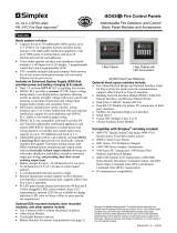
To install the hardware, place the PC in the desired location and connect the
equipment you will use with the system (printer, mouse, etc.). A typical 4190
Information Management System hardware configuration is shown in
Figure 2-1.
Note: Re-seat the various PC boards into the motherboard. This
helps ensure that you have complete electrical connections.
The IMS rack-mount (18” LCD monitor [459 mm]) is shown in Chapter 4.
NETWORK INTERFACE
UL CARD
VIDEO BOARD\BUS MOUSE
TOUCH SCREEN
POWER
SUPPLY
UPS
MONITOR
PRINTER
POWER IN
4190 NETWORK COMM
4190 NETWORK COMM
Figure 2-1. Typical 4190 Information Management System Block
Diagram
WARNING:
Do not plug the keyboard or keyboard adapter into a powered unit! This
will damage the CPU board. All equipment must be powered down before
adding any hardware.
Continued on next page
Connecting the IMS to the System
Connecting the Equipment
DACR

2-6
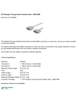
As you connect the equipment, refer to the figures below and the instructions
that follow.
Figure 2-2. Computer Rear Panel Layout – 2.8 Ghz or Faster
System using PCI 4190 Network Cards (Windows 2000
Platform)
Continued on next page
Connecting the IMS to the System, Continued
Connecting the Equipment
(Continued)
AC Power
Bracket for
4190-8103 only
Fan
Monitor
Sound
Card
QUAD 1
Serial Port
4190 Network
Card 3
USB
Video
Connector for
4190-8103 only
UL I/O Card
(If Used)
Mouse/
Keyboard
QUAD 2
Serial Port
4190 Network
Card 2
4190 Network
Card 4
4190 Network
Card 1

2-7
Position the monitor close enough to the PC so that you can connect the cables
from the monitor to the PC and perform the following steps:
1. Connect the touchscreen controller cable to PC Serial Port, COM 1 or
COM 2 is preferred.
2. Connect the other end of the cable to the touchscreen input connector on the
back of the monitor.
Connect the mouse by completing the following steps:
1. Locate the mouse/keyboard connector on the back of the PC.
2. Plug the connector on the end of the mouse cable into the mouse/keyboard
adapter cable on the PC.
Connect the keyboard by completing the following steps:
1. Locate the mouse/keyboard connector on the back of the PC.
2. Plug the connector on the end of the keyboard cable into mouse/keyboard
adapter cable on the PC.
If you have a parallel software key, connect it by completing the following
steps:
1. Locate the LPT1 connector on the back of the PC.
2. Plug the software key into the LPT1 connector.
3. If desired, plug the printer cable into the software key.
If your PC has a working USB port, you may connect a USB software key by
inserting it into the USB Port.
NOTE: THIS SHOULD BE DONE AFTER THE SECURITY SERVICE
SOFTWARE IS INSTALLED ON THE PC.
For instructions on installing the Security Service, refer to Installing the
Software Security System, 579-825.
Connect the printer by performing the following steps:
1. Locate the serial Com port on the PC that was selected in the program.
2. Plug harness 733-937 into the printer and complete the connections per
Printer Installation Instructions 579-233.
Continued on next page
Connecting the IMS to the System, Continued
Connecting a Touchscreen
Monitor
Connecting the Mouse
Connecting the Keyboard
Connecting the Software Key
Connecting the Printer
(Optional)

2-8
Connect the Uninterruptible Power Supply (UPS) by completing the following
steps:
1. Plug the PC, printer, and monitor power cords into the AC outlet, which is
integral to the equipment rack.
2. Connect the dedicated branch circuit to the AC power input of the UPS.
3. Connect the output of the UPS (in conduit) to the AC input terminals
provided on the equipment rack.
4. Connect the transfer contacts of the UPS to the first of the general-purpose
I/O points on the UL I/O card (see diagram 841-947 for interconnection
specifics).
Note: A UPS (La Marche Series A-31 and A-36D) is required for
fire-protective signaling applications.
Complete the following steps for each network interface card you are installing.
You can install up to four network interface cards in an IMS.
1. Locate the network interface card on the back of the PC.
2. Connect the cable from the previous node’s right port to the top connector
on the network card.
3. Connect the next node’s left port to the bottom connector on the network
card.
Connecting the IMS to the System, Continued
Connecting the Optional
Uninterruptible Power Supply
(UPS)
Connecting to a Network
/