Page is loading ...

4010ES
Fire Alarm System
Installation
Guide
579-989
Rev. M


iii
Copyrights, Trademarks, Cautions, Warnings and Regulatory Info
Copyrights and
Trademarks
©2011 - 2016 Tyco Fire Protection Products. All rights reserved.
Specifications and other information shown were current as of publication and are subject to
change without notice. TYCO, SIMPLEX, and the product names listed in this material are
marks and/or registered marks. Unauthorized use is strictly prohibited.
Cautions,
Warnings and
Regulatory
Information
READ AND SAVE THESE INSTRUCTIONS- Follow the instructions in this installation
manual. These instructions must be followed to avoid damage to this product and associated
equipment. Product operation and reliability depend upon proper installation.
DO NOT INSTALL ANY SIMPLEX
®
PRODUCT THAT APPEARS DAMAGED- Upon
unpacking your Simplex product, inspect the contents of the carton for shipping damage. If
damage is apparent, immediately file a claim with the carrier and notify an authorized Simplex
product supplier.
ELECTRICAL HAZARD - Disconnect electrical field power when making any internal adjust-
ments or repairs. All repairs should be performed by a representative or authorized agent of
your local Simplex product supplier.
STATIC HAZARD - Static electricity can damage components. Handle as follows:
• Ground yourself before opening or installing components.
• Prior to installation, keep components wrapped in anti-static material at all times.
EYE SAFETY HAZARD - Under certain fiber optic application conditions, the optical output of
this device may exceed eye safety limits. Do not use magnification (such as a microscope or
other focusing equipment) when viewing the output of this device.
FCC RULES AND REGULATIONS – PART 15 - This equipment has been tested and found to
comply with the limits for a Class A digital device pursuant to Part 15 of the FCC Rules. These
limits are designed to provide reasonable protection against harmful interference when the
equipment is operated in a commercial environment. This equipment generates, uses, and can
radiate radio frequency energy and, if not installed and used in accordance with the instruction
manual, may cause harmful interference to radio communications. Operation of this equipment
in a residential area is likely to cause harmful interference in which case the user will be
required to correct the interference at his own expense.
SYSTEM REACCEPTANCE TEST AFTER SOFTWARE CHANGES - To ensure proper system
operation, this product must be tested in accordance with NFPA 72® after any programming
operation or change in site-specific software. Re-acceptance testing is required after any
change, addition or deletion of system components, or after any modification, repair or
adjustment to system hardware or wiring.
All components, circuits, system operations, or software functions, known to be affected by a
change must be 100% tested. In addition, to ensure that other operations are not inadvertently
affected, at least 10% of initiating devices that are not directly affected by the change, up to a
maximum of 50 devices, must also be tested and proper system operation verified.
NFPA 72® is a registered trademark of the National Fire Protection Association.


v
Table of Contents
Copyrights, Trademarks, Cautions, Warnings and Regulatory Info............................. iii
Copyrights and Trademarks ................................................................................................... iii
Cautions, Warnings and Regulatory Information ................................................................... iii
Chapter 1 Overview ...........................................................................................1-1
Introduction ..........................................................................................................................1-1
In this chapter ......................................................................................................................1-1
Standalone configuration ...............................................................................................1-2
Overview ..............................................................................................................................1-2
Standalone system layout ....................................................................................................1-2
Network configuration .....................................................................................................1-3
Overview ..............................................................................................................................1-3
Connecting network loops ....................................................................................................1-4
Network communication .......................................................................................................1-4
Chapter 2 Basic Hardware ................................................................................2-1
Introduction ..........................................................................................................................2-1
In this chapter ......................................................................................................................2-1
CPU ...................................................................................................................................2-2
Overview ..............................................................................................................................2-2
CPU LEDs ............................................................................................................................2-3
CPU jumper settings ............................................................................................................2-5
CPU switches .......................................................................................................................2-6
CPU connectors/ports/terminal block ...................................................................................2-6
CPU card specifications .......................................................................................................2-7
Operator interface ...........................................................................................................2-8
Overview ..............................................................................................................................2-8
Main system supply (MSS) .............................................................................................2-9
Overview ..............................................................................................................................2-9
MSS LEDs and jumpers .....................................................................................................2-11
MSS specifications .............................................................................................................2-12
48-LED Module ...............................................................................................................2-14
Overview ............................................................................................................................2-14
48-LED Module specifications ...........................................................................................2-15
System power ................................................................................................................2-16
Main system power ............................................................................................................2-16
Backup batteries ................................................................................................................2-16
Chapter 3 Panel configurations ........................................................................3-1
Introduction ..........................................................................................................................3-1
In this chapter ......................................................................................................................3-1
One-bay 4010ES Panels ..................................................................................................3-2
Overview ..............................................................................................................................3-2
Optional modules .................................................................................................................3-4
Back box mechanical specifications ....................................................................................3-5
Two-bay 4010ES Panels ..................................................................................................3-6
Overview ..............................................................................................................................3-6
Optional modules .................................................................................................................3-9
Back box mechanical specifications ....................................................................................3-9

vi
Table of Contents
Chapter 4 Orderable panels and devices ........................................................4-1
Introduction ..........................................................................................................................4-1
In this chapter ......................................................................................................................4-1
Panels ...............................................................................................................................4-2
One-bay 4010ES Panels .....................................................................................................4-2
Two-bay 4010ES Panels .....................................................................................................4-2
Optional modules ............................................................................................................4-3
Local optional modules ........................................................................................................4-3
Remote devices ...................................................................................................................4-4
Adjunct features ...................................................................................................................4-5
End user programming tools ................................................................................................4-5
LED kits for the 48-LED Module ..........................................................................................4-5
Chapter 5 Installing 4010ES systems ..............................................................5-1
Introduction ..........................................................................................................................5-1
In this chapter ......................................................................................................................5-1
Mounting the panel ..........................................................................................................5-2
Installing the back box .........................................................................................................5-2
Attaching the dead front .......................................................................................................5-3
Attaching doors ....................................................................................................................5-4
General field wiring guidelines ......................................................................................5-5
Power-limited guidelines ......................................................................................................5-5
Connecting 4010ES basic components .........................................................................5-7
Connecting the CPU and the operator interface ..................................................................5-7
Connecting the MSS ............................................................................................................5-9
Connecting the 48-LED Module .........................................................................................5-10
RUI wiring .......................................................................................................................5-11
Overview ............................................................................................................................5-11
Installing the optional modules ....................................................................................5-13
Overview ............................................................................................................................5-13
Installing one-block and two-block cards ...........................................................................5-13
Address configuration DIP switch ...............................................................................5-14
Overview ............................................................................................................................5-14
Connecting main system power ...................................................................................5-16
Overview ............................................................................................................................5-16
Panel power-up sequence .................................................................................................5-16
Chapter 6 MSS field wiring ...............................................................................6-1
Introduction ..........................................................................................................................6-1
In this chapter ......................................................................................................................6-1
Power supply wiring distances ......................................................................................6-2
Overview ..............................................................................................................................6-2
Class A NAC wiring table .....................................................................................................6-2
Class B NAC wiring table .....................................................................................................6-3
MSS NAC field wiring guidelines ...................................................................................6-4
Guidelines ............................................................................................................................6-4
MSS NAC wiring ..............................................................................................................6-5
Class A NAC Wiring .............................................................................................................6-5
Class B NAC wiring ..............................................................................................................6-6

vii
Table of Contents
MSS IDNet wiring .............................................................................................................6-7
Overview ..............................................................................................................................6-7
Wiring parameters ................................................................................................................6-7
Class A wiring ......................................................................................................................6-8
Class B wiring ......................................................................................................................6-9
MSS auxiliary power wiring ..........................................................................................6-10
Guidelines ..........................................................................................................................6-10
Wiring .................................................................................................................................6-11
MSS auxiliary relay wiring ............................................................................................6-12
Guidelines ..........................................................................................................................6-12
Wiring .................................................................................................................................6-12
Chapter 7 PC software connections ................................................................7-1
Introduction ..........................................................................................................................7-1
In this chapter ......................................................................................................................7-1
Software modes ...............................................................................................................7-2
Software modes ...................................................................................................................7-2
Ethernet service port .......................................................................................................7-4
Ethernet service port overview .............................................................................................7-4
Chapter 8 System wiring checkout and earth fault diagnostics ...................8-1
Introduction ..........................................................................................................................8-1
In this chapter ......................................................................................................................8-1
Checking system wiring .................................................................................................8-2
Overview ..............................................................................................................................8-2
Using the multimeter ............................................................................................................8-2
Meter readings .....................................................................................................................8-3
Earth fault diagnostics ....................................................................................................8-4
Overview ..............................................................................................................................8-4
General guidelines ...............................................................................................................8-4
Earth fault searching from the front panel ....................................................................8-6
Overview ..............................................................................................................................8-6
Access level selection ..........................................................................................................8-6
Starting the Earth Fault Search ............................................................................................8-6
Search Option A: Select Location ........................................................................................8-7
Search Option B: Select Location ........................................................................................8-7
Search Option C: Last Search Result ..................................................................................8-8
Completing the search .........................................................................................................8-8
Earth fault search results ...............................................................................................8-9
Overview ..............................................................................................................................8-9
Non-point faults ....................................................................................................................8-9
Point Faults ..........................................................................................................................8-9
Fault Not Found .................................................................................................................8-10
No Fault .............................................................................................................................8-10
Result Not Available ...........................................................................................................8-10
Chapter A ULC programming requirements ...................................................A-1
Introduction ......................................................................................................................... A-1
In this chapter .....................................................................................................................A-1

viii
Table of Contents
Common earth fault ground indicator .......................................................................... A-2
Overview .............................................................................................................................A-2
Step 1. Open CPU card properties dialog ...........................................................................A-2
Step 2. Program the LED ....................................................................................................A-3
Simultaneous alarm display .......................................................................................... A-4
Overview .............................................................................................................................A-4
Creating annunciation zone lists .........................................................................................A-4
Programming the address and mode for each LED ............................................................A-5
Setting alarm verification timer to Canadian operation .............................................. A-7
Introduction ......................................................................................................................... A-7
Procedure ...........................................................................................................................A-7
Setting Alarm Reset/Inhibit Timer ................................................................................. A-8
Overview .............................................................................................................................A-8
Enabling Alarm Reset/Inhibit Timer ....................................................................................A-8
Alarm Cutout Timer ........................................................................................................ A-9
Overview .............................................................................................................................A-9
Enabling Alarm Cutout Timer ..............................................................................................A-9
Chapter B UL programming requirements ......................................................B-1
Introduction ......................................................................................................................... B-1
In this chapter .....................................................................................................................B-1
Setting Alarm Verification to US operation .................................................................. B-2
Overview .............................................................................................................................B-2
Procedure ...........................................................................................................................B-2
Alarm Cutout Timer ........................................................................................................ B-3
Overview .............................................................................................................................B-3
Enabling Alarm Cutout Timer ..............................................................................................B-3
Non Steady Visual Evacuation system option ............................................................. B-4
Overview .............................................................................................................................B-4
Chapter C Simplex special application NAC-compatible notification appliances and
accessories ........................................................................................................C-1
Chapter D Cooper Wheelock appliances compatible with 4010ES Wheelock protocol
for special applications .....................................................................................D-1
Overview .............................................................................................................................D-1
Synchronizing horn strobes ................................................................................................D-1
Synchronizing strobes .........................................................................................................D-2
Appliances with synchronizing strobes ...............................................................................D-3
Synchronizing horns ...........................................................................................................D-4
Coded audible appliances ...................................................................................................D-5
Non-synchronizing appliances ............................................................................................D-5

1-1
Chapter 1
Overview
Introduction The 4100ES FACP panel is an expandable fire alarm panel, which can be used as a standalone
system, or can be networked with the following panels to create a larger network:
• 4002
• 4010
• 4020
• 4100
• 4100U
• 4100ES
• 4010ES
• 4007ES
• 4190 TrueSite Workstation
• 4190 TrueSite Incident Commander
• 4190 Network System Integrator
The 4100ES comes with basic system components pre-installed. This chapter provides an
overview of standalone and network 4010ES panel concepts:
Standalone. Comprised of one 4010ES FACP and its assorted notification appliances,
initiating devices, and signaling line circuit devices.
Network. Multi-FACP systems connected by 4120 network cards. Each panel maintains the
status and control of its own circuit points, while monitoring and controlling activity at other
locations. Network nodes may perform similar tasks, or may be dedicated to specific
functions.
In this chapter This chapter covers the following topics:
Topic Page
Standalone configuration 1-2
Network configuration 1-3

1-2
Standalone configuration
Overview The standalone version of the 4010ES is used for smaller, or single-building applications. A
standalone system is ideally placed into a small building that requires a limited number of
notification appliances and initiating devices.
If a small building is being expanded, or if other buildings are being constructed in the same
general area, as in a campus application, the standalone 4010ES can be upgraded to a network
system and linked with other 4010, 4100, 4100U, 4100ES and 4010ES panels to create a larger
network.
Note: You must order and install the 4010-9902 and the 4010-9922 network cards into the standalone
system to enable network functionality.
Standalone
system layout
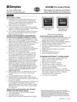
Figure 1-1 below shows the layout of the 4010ES standalone configuration.
Figure 1-1. Standalone 4010ES system
4010ES Panel
Remote Annunciation
(Graphical or LCD)
TrueAlert Non-Addressable
Devices
TrueAlarm Thermal
Sensor with Base
Monitor and
Control ZAMs
Addressable Station
Remote Line Powered
Isolator
Supervised
IAM
TrueAlarm Smoke
Sensor with Base
To additional IDNet devices
4009A Series
Devices
TrueAlert Non-Addressable
Devices
to Device(s)
to Device(s)
RUI
TrueAlert Non-Addressable
Devices
TrueAlert Non-Addressable
Devices
4010ES NAC
IDnet
Note: Some 4009-series
devices are controlled
through RUI and not
IDNet
4009T or
4009TPS
TrueAlert Addressable
Devices

1-3
Network configuration
Overview The 4010ES can be expanded to a network system by using the 4010-9902 and the 4010-9922
network interface cards (NICs). When a NIC is installed into a 4010ES host panel, it is used to
connect to up to 98 other network nodes. Nodes may consist of other host 4010ES panels, or
they may be completely different: 4010ES FACPs and TrueSite Workstation (TSW) are
examples of what could be used as nodes. A node is a self-sufficient FACP that controls
appliances and devices, which also has the capability of controlling and communicating with
other nodes.
The network configuration supports two prevalent architectures or wiring configurations: hub
(or ring), or star. A networked system can also use a combination of the two.
The hub configuration consists of a main loop with nodes connected in a radial manner. The
star configuration consists of several nodes connected directly to one common node. Physical
bridge cards are used for the star configuration. Physical bridges reduce the amount of wire that
would otherwise be needed to connect all nodes in a loop. A combination of the two styles is
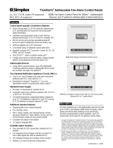
illustrated in Figure 1-2.
Figure 1-2. Hub/ring configuration
Ring Topology
Physical Bridge Links
(Star Topology)
TSW
Network Display Unit
(NDU)
Hub Node
Distributed Remote
Node Locations
Note: Physical Bridge
links in a 4010ES
requires a two-bay box

1-4
Network configuration, continued
Connecting
network loops
Network loops can be joined by using physical bridge cards. There may be no more than two
Style 7 network loops, two hub configurations, connected in tandem. For every two loops that
are interconnected using one physical bridge, there can be a maximum of three physical
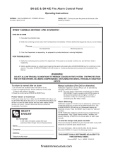
bridges used in a star configuration. See Figure 1-3.
Figure 1-3. Interconnected loop configuration
Network
communication
Network communication is achieved using the 4010-9902 and the 4010-9922 NICs. Each
network node requires a NIC. Once the FACP is a network node, it may be programmed to be
fully in control of other nodes, to be fully passive, or anywhere in between.
The 4010-9902 and the 4010-9922 NICs are option cards that use a PDI connector to
communicate with the CPU. The NICs allow for communication between each panel using a
fiber or twisted shielded pair wire in a Style 4 or Style 7 wiring configuration.
The NICs are designed to be connected in a point-to-point arrangement, so that one wire fault
does not cause the entire system to fail. The point-to-point arrangement provides the most
secure and fault-tolerant wiring possible.
Two types of media cards can be used with the NICs:
• The Fiber-Optic Media (4010-9819) card can be used for electrically noisy environments,
or for connecting externally to other buildings.
• The Wired Media Card (4010-9818) is used in all other types of applications.
Up to two media cards can be plugged into each NIC. The same NIC can use a combination of
different types of media boards; for example, a NIC may have a Wired Media card connected
to the left port, a Fiber-Optic Media card connected to the right port.
For setup and installation of a physical bridge card, refer to document 579-184: 4100/4120/
4010-Series Physical Bridges and Media Modules.
For setup and installation of network interface cards, refer to document 579-956: 4010ES
Network Interface and Media Card Installation Instructions.
Remote Loop
Physical Bridge Link
Local Loop
Physical Bridging
(Star Configuration - 3 max)
TSW
Physical
Bridge
Link
Physical Bridge Links
Hub Node
Hub
Node
Remote
Node

2-1
Chapter 2
Basic Hardware
Introduction The 4010ES FACPs are one-bay or two-bay back boxes with a dead front and glass door,
containing a set of pre-installed basic system components:
• Dead front-mounted CPU (2x40 character LCD or InfoAlarm)
• Operator interface
• Main system supply (MSS) (notification appliance circuits and system power)
• 48-LED Module (for some 4010ES configurations)
• IDNet+ or MX Loop circuit (for initiating and other devices)
• PDI Blocks for optional modules
In addition to the basic modules, optional modules can be installed inside the one-bay or two-
bay 4010ES panels. The types of modules available depend on the panel configuration, as well
as the accessibility, and availability, of the power distribution interface (PDI) blocks. The
number of available PDI blocks depends on the system ordered. See Chapter 3, “Panel
Configurations.”
In this chapter This chapter covers the following topics:
Topic Page
CPU 2-2
Operator interface 2-8
Main system supply (MSS) 2-9
48-LED Module 2-14
System power 2-16

2-2
CPU
Overview The CPU card (Figure 2-1 and Figure 2-2) is the main decision maker in the 4010ES FACP. It
holds all job information, current system status, and communicates to all slaves connected to
the 4010ES panel. A 4010ES CPU contains the following features:
• 2 x 40 LCD display and piezo (non-InfoAlarm systems only) - Annunciation for
supervisory, trouble, priority 2 and fire alarm signals.
• Compact flash socket (card pre-installed) - Alternate exec and job storage.
• Ethernet service port - PC connection used by Simplex service personnel.
• Serial service port - Interface for service equipment or Simplex service personnel.
• Style 4/7 Remote Unit Interface - Remote connection to system components not located
within 4010ES box.
Figure 2-1. Dead front-mounted CPU with a 2 x 40 display (front view)
Continued on next page
SUPERVISORY LED (LED17)
2x40 LCD
USER-DEFINABLE LEDs TROUBLE LED (LED16)
(LED11-LED14, LED21, LED22)
CONTROL KEY LEDs PRIORITY 2 ALARM LED AC POWER LED (LED20)
(LED23-LED25)
(LED18)
FIRE ALARM LED (LED19) ALARM SILENCED LED (LED15)
Note: All LEDs on the front side of the board are used for standard fire
alarm functions and are visible through the dead front membrane.

2-3
CPU, continued
Overview
Figure 2-2. Dead front-mounted CPU with a 2 x 40 display (back view)
CPU LEDs The tables below outline the functions of the LEDs on the CPU card.
Continued on next page
RUI TROUBLE LEDs (LED1-LED3)
RUI ENABLE JUMPER (P1)
BATTERY (BT1)
PIEZO CONNECTION (BUZ1)
BATTERY ENABLE LCD CONTRAST RUI SHIELD
COMPACT FLASH (P3) JUMPER (P5) ADJUST (R23) JUMPER (P2)
COLD START KEYPAD MEMBRANE 24V POWER/COMMS
SWITCH (SW3) CONNECTOR (P8) CONNECTORS (P9 & P10)
BOOTLOADER STATUS LEDs (LED7-LED10) SERIAL SERVICE PORT (P11)
RESET SWITCH (SW1) ETHERNET SERVICE PORT (J7)
ETHERNET STATUS LED (LED5) & ACTIVITY LED (LED6)
RUI PLUGGABLE TERMINAL BLOCK (TB1)
Table 2-1. Reset LED
Reference
designator
Silkscreen name Color Status
LED4 RESET Yellow
ON = CPU is in reset
FLASHING = Board is unable to come
out of reset. Possibly corrupt CFIG, or
board needs to be replaced.
OFF = CPU is running normally

2-4
CPU, continued
CPU LEDs
Continued on next page
Table 2-2. Ethernet LEDs
Reference
designator
Silkscreen name Color Status
LED5 STATUS Green ON = Cable connected
LED6 ACTIVITY Red FLASHING = Ethernet activity
Table 2-3. RUI trouble LEDs
Reference
designator
Silkscreen name Color Status
LED1 OPEN Yellow ON = Class A fault (open-circuit) or a short
LED2 B SHORT Yellow ON = Short-circuit on the primary side
LED3 A SHORT Yellow ON = Short-circuit on the secondary side
Table 2-4. Front panel LEDs
Reference
designator
Silkscreen name Color Status
LED11
USER-DEF A
Red ON = User-definable key A active (Note)
LED12 Yellow ON = User-definable key A active (Note)
LED13
USER-DEF B
Yellow ON = User-definable key B active (Note)
LED14 Red ON = User-definable key B active (Note)
LED15
ALARM
SILENCED
Yellow ON = Alarm silenced
LED16 TRBL Yellow ON = Trouble
LED17 SUPV Yellow ON = Supervisory
LED18 PRI2 Red ON = Priority 2 alarm
LED19 FIRE Red ON = Alarm
LED20 AC POWER Green
ON = System power is functioning
properly
LED21
USER-DEF C
Yellow ON = User-definable key C active (Note)
LED22 Green ON = User-definable key C active (Note)
LED23 CTRL 1 Yellow ON = Control key 1 active
LED24 CTRL 2 Yellow ON = Control key 2 active
LED25 CTRL 3 Yellow ON = Control key 3 active
Note: Only one LED in each user-definable pair will be on at a time, never both.

2-5
CPU, Continued
CPU LEDs
CPU jumper
settings
Table 2-5. Bootloader status LEDs
Reference
designator
LED7 LED8 LED9 LED10
Silkscreen
Name
AB C D
Color Green Green Green Green
Status
Bootloader
Initialization
On (0.25 s)
Off (0.25 s)
On (0.25 s)
Off (0.25 s)
On (0.25 s)
Off (0.25 s)
On (0.25 s)
Off (0.25 s)
Bad Master
CRC or No
Master
Present
Off Off Off On
Diagnostic
Fail - RAM
On Off Off On
Diagnostic
Fail -
Bootloader
CRC
Off On Off On
Downloading
Master
On On Off On
Downloading
CFIG
Off Off On On
Downloading
MsgLib
On Off On On
Downloading
Bootloader
Off On On On
Download
Successful
On On On On
Table 2-6. CPU settings
Reference designator Silkscreen name Position Function
P5 BATTERY
1-2 Enable RAM battery backup
2-3 (default) Disable RAM battery backup
P1 RUI CKT
1-2 (default) Disable RUI
2-3 Enable RUI
P2 RUI SHIELD
1-2 (default) RUI shield tied to 24C (Note)
2-3 RUI shield tied to earth
Note: Some devices that connect to RUI have inherently grounded shield terminals, in which case, 24C
cannot be used. If 24C is used, a negative earth fault will occur.

2-6
CPU, continued
CPU switches
CPU connectors/
ports/terminal
block
Table 2-7. Switches
Reference
designator
Silkscreen name Function
SW1 RESET
Short press (< 3 seconds) to activate a software-controlled
reset (warm start).
Press and hold (> 3 seconds) to force a hardware reset
(also a warm start).
Generally, unless the CPU card appears to be locked up,
you should always use the software-controlled reset.
A warm start preserves the logs and the disabled status of
any points that are in the disabled state.
SW3 COLD START
During startup, press and hold this button to clear all history
logs and enable any points that were previously disabled.
Table 2-8. Connectors/ports/terminal block
Reference
designator
Silkscreen name Function
P3 COMPACT FLASH
Used for alternative job/exec storage. Card does not
“run” out of compact flash.
P8
KEYPAD
MEMBRANE
Used to communicate user inputs from the keypad
membrane to the CPU card.
P9 & P10
24 V POWER/
INTERNAL COMMS
Used to provide the necessary connections to daisy
chain 4100 comms and 24 VDC card power in an in-out
fashion. 24 VDC card power originates from the MSS.
4100 comms originates from the CPU card.
P11
SERIAL SERVICE
PORT
Used to connect the CPU card to the remote service
gateway. It may also be used as a service port if the
Ethernet service port is not available.
J7
Ethernet SERVICE
PORT
Used to connect the panel to a local PC through the front
panel Ethernet connection board, or 4010-9914 BNIC.
TB1
RUI A-, RUI A+,
SHIELD, RUI B-, RUI
B+
Remote user interface (RUI) used for communication
between the CPU and remote slaves.

2-7
CPU, continued
CPU card
specifications
Table 2-9 shows the battery current draw for the CPU card.
Table 2-10 shows the maximum draw over the voltage range.
Note: CPU InfoAlarm supervisory and alarm current draws are both the same as the supervisory current
draw.
Table 2-9. Battery standby (24 V)
Configuration Supervisory current draw Alarm current draw
RUI disabled 124 mA 173 mA
RUI enabled - no load 149 mA 198 mA
RUI enabled - full load 176 mA 225 mA
Table 2-10. Maximum draw over voltage range
Configuration Supervisory current draw Alarm current draw
RUI disabled 144 mA 208 mA
RUI enabled - no load 167 mA 226 mA
RUI enabled - full load 186 mA 248 mA

2-8
Operator interface
Overview The two operator interfaces which are available with the 4010ES are shown below.
The operator interface is used to obtain fire alarm, priority 2, supervisory, trouble, and other
statuses through the display and LEDs. Control functions are accessed using dedicated and
user-programmable keys.
Figure 2-3 is the standard 2 x 40 LCD operator interface. This model includes a 2 line by 40
character liquid crystal display. The membrane is available in both English and French.
Figure 2-3. Standard operator interface
Figure 2-4 is the InfoAlarm operator interface. This model includes a larger graphical display,
which can display more information simultaneously.
Note: The InfoAlarm operator interface can only be installed on two-bay 4010ES panels. See Chapter 3,
“Panel Configurations,” for details on two-bay panels.
Figure 2-4. InfoAlarm operator interface
A B C D E F G H I
J K L M N O P Q R
'SP' ( ) , # :
S T U V W X Y Z /
ZONE
1
SIG
2
AUX
3
FB
4
IO
5
IDNet
6
P
7
A
8
L
9
NET ADDR
0
C/Exit
Menu Enter
Pre viou s
Next
Page Dn
Page Up
AC
Power
ALARMS
Fi re
Alarm
Priority 2
Alarm
WARNINGS
System
S upervi s ory
System
Troubl e
Alarm
Silenced
Fire Alarm
Ack
Priority 2
Ack
Supv
Ack
Troubl e
Ack
Alarm
Silence
System
Reset
Ground Fault
Waterflow-West
Waterflow-East
City Disconnect
Manual Evac
Door Holder
Bypass
Drill
Language
Toggle
Smoke Sensor
Almost Dirty Check
Lamp Test
/