Extron DTP2 T 202 FB User manual

Category
Video splitters
Type
User manual
1
DTP2 T 202 FB • Setup Guide
This guide provides instructions for an experienced installer to install
the Extron DTP2 T 202 FB switching transmitter into an Ackermann
GB3 (OBO Betterman), MK Electric CableLink Plus Modular, MK Electric
CableLink Plus Single Pan,
ElectraPlan, or PUK oor box
and to make all connections.
The transmitter switches
between two digital video
inputs (HDMI and DisplayPort)
and, paired with a compatible
receiver, can extend the
selected signal up to 330 feet
(100 m).
Installation
Planning
CAUTION: Failure to check these items may result in personal injury or property damage.
ATTENTION : La non-vérication des éléments listés ci-dessous peut provoquer des blessures ou dommages matériels.
Check that the installation meets the building, electrical, and safety codes.
Mounting and Cabling
Typical Floorbox
1
2
3
Step 1 Preparing the floor box
a. Install the oor box as directed by the manufacturer.
NOTE: Run all required cables and secure them with cable clamps.
b. Turn off or disconnect all equipment power sources.
Step 2 Installing adapters
a. Determine a position in the oor box to mount the switching transmitter (see the image
at right).
b. Identify the applicable adapter plates for the oor box (see the table below).
c. Install adapter plates to the same pair of mounting slots (see the table below for slot
recommendations) for the same position in the oor box. Slide the top ange into the
mounting slot and rotate the adapter plate down so the bottom ange rests against the
wall of the oor box.
Floor Box Adapter Plates Positions
Highest
Mounting Slot
Additional Notes
Ackermann GB3
(OBO Betterman)
995241 (2)
995241 (2) and 995242 (1)
1 and 3
2
3rd from top
For position 2, use the provided screws to attach
the 995242 adapter plate to either 995241
adapter plate.
MK Electric CableLink Plus
Single Pan
995243 (2) 1 and 3
N
/A
Do not use position 2. Use mounting screws to
secure the adapter plates to the oor box (see
figure 3 on page 3).
MK Electric CableLink Plus Modular 995244 (2) 1, 2, and 3 3rd from top
ElectraPlan 995300 (2) 1, 2, and 3 3rd from top
PUK 995300 (2) 1, 2, and 3 3rd from top
IMPORTANT:
IMPORTANT:
Go to www.extron.com for the complete
user guide, installation instructions, and
specifications before connecting the
product to the power source.
w
DTP2 T 202 FB
HDMI IN
AUDIO IN DISPLAYPORT IN
HDMI
DP
SIGNAL
HDCP
AUTO
CONFIG RESET
Top Panel
K
LJ
Figure 1. DTP2 T 202 FB Unit features
Side (under adapter plate)
(Before installation in floor box)
Side (above adapter plate)
(After installation in floor box)
Top
A
DC power input
B
Remote RS-232
C
RS-232/IR Over TP output
D
DTP output
E
Send power switch
F
TP function switch
G
HDMI input
H
Audio input
I
DisplayPort Input
J
Conguration (USB)
K
Reset button
L
LED indicators
OVER TP
OUT
IR RS-232
RS-232
REMOTE
POWER
SEND POWER
12V
1.4A MAX
OFFHDBTDTP
GRxTxRxTxGRx Tx
LINK
SIG
Side Panel
G
EF
H
I
D
A
B
C
2
DTP2 T 202 FB • Setup Guide (Continued)
Step 3 — Make side panel connections and set switches under the adapter plates
A
Power (see figure 1 on page 1) — Connect the included 12 VDC power supply to either unit,
transmitter or receiver, as shown at right. Use the included tie-wrap to strap the cord to the
captive screw connector.
Connect an IEC power cord between the power supply and a 100-240 VAC, 50-60 Hz source.
NOTE: If the TP switch (
F
) is in DTP, one power supply can power both units.
If the switch is in
HDBT, each unit requires its own power supply.
B
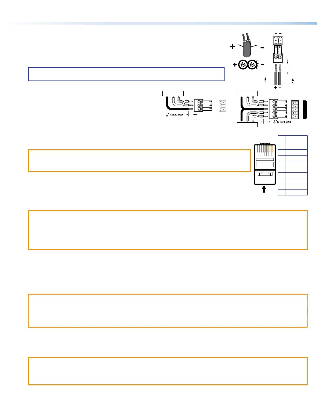
Remote RS-232 port — For serial RS-232 control, connect a
host device or control system to the 3.5 mm, 3-pole captive
screw connector. See the drawing at right.
C
RS-232 and IR port — To pass serial or infrared data or
control signals on the Over DTP RJ-45 output, connect the
controlling device to the transmitter via the RS-232 and IR
captive screw port. Connect the device to be controlled to the receiver. See the drawing at right.
D
Out port— Connect the Out (RJ-45) port to the DTP In port on the receiver. Extron recommends
that you terminate both cable ends in accordance with the following, at a minimum:
TIA/EIA T 568B and 24 AWG, solid conductor, shielded cable with 400 MHz bandwidth.
ATTENTION:
Do not connect this connector to a computer data or telecommunications network.
Ne connectez pas ces port à des données informatiques ou à un réseau de télécommunications.
Signal LED indicator — Lights when the device is transmitting a video signal or a test pattern.
Link LED indicator — Lights when a valid link between a DTP or HDBT input and output is established.
E
Send Power toggle switch — In a system with a DTP2 receiver, set the toggle switch to the Send Power
position (left) on the powered unit to enable sending power to the unpowered unit. Set the toggle switch to
the Off position (right) on the DTP2 unit that is to receive power.
ATTENTION:
The DTP2 device is congured to output power to DTP2 models only. If connected to a legacy DTP device, set the Send
Power toggle switch to the Off position (right). Failure to turn the power off will damage the connected legacy DTP device.
L
’appareil DTP2 est conguré pour fournir une alimentation aux modèles DTP2 uniquement. S’il est connecté à un modèle
DTP traditionnel, veuillez positionner l’interrupteur à bascule Send Power sur « Off » (droite). Si l’interrupteur n’est pas
positionné sur off, vous risquez d’entraîner la défaillance de l’appareil DTP connecté.
F
TP function switch
If the receiving device is in the Extron DTP series, set this switch to DTP. The TP output consists of HDMI with embedded audio,
analog audio, RS-232 and IR, and remote power. The transmitter and receiver can be powered by one 12 VDC power supply
connected to either unit.
For an HDBaseT-enabled receiver type, set this switch to HDBT position. The TP output consists of HDMI with embedded audio plus
RS-232 and IR. The transmitter and receiver each requires its own 12 VDC power supply.
ATTENTION:
Position this switch BEFORE connecting the appropriate device to the TP connector. Failure to comply can damage the
endpoint.
Positionnez le sélecteur AVANT de connecter l’appareil approprié au connecteur TP. Ne pas respecter cette procédure
pourrait endommager le point de connexion.
Step 4 — Mount the unit in the floor box
a. Place the DTP2 T 202 FB in the desired position in the oor box so that the side panel connectors face towards the opening of the
oor box.
ATTENTION:
Ensure there is enough space between the top panel connectors and the lid of the oor box so the lid fully closes.
Assurez vous qu’il y ait assez d’espace entre les connecteurs du panneau supérieur et le couvercle du boîtier de sol an
que celui-ci puisse se fermer entièrement.
b. Using the provided self-threading screws, secure the DTP2 T 202 FB to the adapter plates (see gures 2 through 5 on the next page).
Power Supply
Output Cord
Ridges
Smooth
Captive
Screw
Connector
3"
16 (5 mm) MAX
SECTION A–A
AA
5
Pin
1
2
3
6
7
8
4
Wire color
White-green
Green
White-orange
White-blue
Orange
White-brown
Brown
Blue
TIA/EIA T
568B
TP Wires
12345678
Pins:
Rx Tx
Tx Rx
Gnd
Gnd
RS-232 Device
IR Device
TxGnd
RS-232 Device
Rx
Rx RxGTx Tx
OVER TP
IR RS-232
RS-232
REMOTE
GRxTx
3
Ackermann GB3 (OBO Betterman) floor box
DTP T FB 332
POWER
DTP T FB 332
REMOTE
RS-232
-
+
G
Rx
T
x
1
2V
A MAX
XTP OUT
NOTE: For position 2, install
adapter plate 995242 to
one of the other adapter
plates.
995242
995241
Figure 2. DTP2 T 202 FB Unit in an Ackermann GB3 (OBO Betterman) Floor Box
MK Electric CableLink Plus Single Pan floor box
DTP
T FB 332
POWER
DTP T F
B 332
REM
O
TE
RS-
232
-
+
G
Rx
Tx
1
2V
A MAX
X
T
995243
995243
Figure 3. DTP2 T 202 FB Unit in an MK Electric CableLink Plus Single Pan Floor Box
MK Electric CableLink Plus Modular floor box
DTP T FB 3
32
P
OWER
DTP T FB 332
RE
MOTE
RS
-232
-
+
G
R
x
Tx
12V
A MAX
XTP OUT
995244
995244
Figure 4. DTP2 T 202 FB Unit in an MK Electric CableLink Plus Modular Floor Box
ElectraPlan or PUK floor box
DTP T FB 332
POWER
XTP T FB 202
REMOTE
RS-
232
-
+
G
Rx
T
x
12V
A MAX
X
T
P
OUT
995300
995300
Figure 5. DTP2 T 202 FB Unit in an ElectraPlan (or PUK) Floor Box
4
68-2985-50 Rev. A
02 20
DTP2 T 202 FB • Setup Guide (Continued)
© 2020 Extron Electronics — All rights reserved. www.extron.com All trademarks mentioned are the property of their respective owners.
Worldwide Headquarters: Extron USA West, 1025 E. Ball Road, Anaheim, CA 92805, 800.633.9876
For information on safety guidelines, regulatory compliances, EMI/EMF compatibility, accessibility, and related topics, see the Extron
Safety and Regulatory Compliance Guide on the Extron website.
Step 5 — Make side panel connections above the adapter plates
G
HDMI input port (see figure 1 on page 1) — Connect an HDMI cable between this port and the HDMI output port of a video source.
NOTE: See “LockIt® Lacing Brackets” to securely fasten the HDMI connector to the transmitter.
H
Audio input — Connect an unbalanced stereo audio source to this 3.5 mm mini stereo jack for an analog audio input.
I
DisplayPort Input port — Connect a DisplayPort cable between this port and the DisplayPort output port of a video source.
Step 6 — Make top panel connections
J
Configuration port — Plug a PC or other controlling device into the switching transmitter via this top panel mini-USB connector for
remote conguration of the switching transmitter.
K
Reset button — This button initiates two levels of reset. See the DTP2 T 202 FB User Guide, available at www.extron.com, for
details.
Operation
After all connected devices are connected and powered on, the system is fully operational. The switching transmitter can be congured
and controlled using Extron Simple Instruction Set (SIS) commands (see the DTP2 T 202 FB User Guide available at www.extron.
com).
Indicators (
L
, see figure 1)
HDMI
DP
SIGNAL
HDCP
AUTO
Power LED Lights when power is applied.
HDMI LED Lights when the HDMI input signal is detected.
DP LED Lights when a DisplayPort input signal is detected.
Signal LED — Lights to indicate when a signal is detected on the selected input.
HDCP LED Lights when the HDMI input signal is encrypted.
Auto LED Lights when device is in auto switch mode. Auto switch is on by default.
When auto switch mode is on, the switcher automatically selects the input, HDMI or DisplayPort, that has a valid signal present. When
signals are present on both inputs, the switcher selects DisplayPort.
NOTE: Auto switch mode can be toggled off and on using the SIS commands. Issue the EnAUSW} SIS command,
where n = 0 (off) or 1 (on). The switcher responds with Auswn
]. See the DTP2 T 202 FB User Guide, available at
www.extron.com, for details.
LockIt
®
Lacing Brackets
Use the included LockIt Lacing Brackets to securely fasten the HDMI cable as follows.
1. Plug the HDMI cable into the panel connection.
2. Loosen the HDMI connection mounting screw from the panel enough to allow the LockIt lacing
bracket to be placed over it. The screw does not have to be removed.
3. Place the LockIt lacing bracket on the screw and against the HDMI connector, then tighten the
screw to secure the bracket.
ATTENTION:
Do not overtighten the HDMI connector mounting screw. The shield it fastens to is very
thin and can easily be stripped.
Ne serr
ez pas trop la vis de montage du connecteur HDMI. Le blindage auquel elle est
attachée est très n et peut facilement être dénudé.
4. Loosely place the included tie wrap around the HDMI connector and the LockIt lacing bracket as shown.
5. While holding the connector securely against the lacing bracket, use pliers or similar tools to tighten the tie wrap, then remove any
excess length.
3
  • Page 1 1
  • Page 2 2
  • Page 3 3
  • Page 4 4

Extron DTP2 T 202 FB User manual

Category
Video splitters
Type
User manual

Ask a question and I''ll find the answer in the document

Finding information in a document is now easier with AI

in other languages